EP0953760B1 - Dosiervorrichtung für eine Emulgieranlage - Google Patents
Dosiervorrichtung für eine Emulgieranlage Download PDFInfo
- Publication number
- EP0953760B1 EP0953760B1 EP99108120A EP99108120A EP0953760B1 EP 0953760 B1 EP0953760 B1 EP 0953760B1 EP 99108120 A EP99108120 A EP 99108120A EP 99108120 A EP99108120 A EP 99108120A EP 0953760 B1 EP0953760 B1 EP 0953760B1
- Authority
- EP
- European Patent Office
- Prior art keywords
- piston
- conduit
- fuel
- emulsifying
- partial
- Prior art date
- Legal status (The legal status is an assumption and is not a legal conclusion. Google has not performed a legal analysis and makes no representation as to the accuracy of the status listed.)
- Expired - Lifetime
Links
- 230000001804 emulsifying effect Effects 0.000 title claims description 15
- 238000006073 displacement reaction Methods 0.000 claims description 3
- 239000000203 mixture Substances 0.000 claims description 2
- 239000007788 liquid Substances 0.000 abstract 5
- 239000012530 fluid Substances 0.000 abstract 1
- 239000000446 fuel Substances 0.000 description 28
- XLYOFNOQVPJJNP-UHFFFAOYSA-N water Substances O XLYOFNOQVPJJNP-UHFFFAOYSA-N 0.000 description 25
- 239000000839 emulsion Substances 0.000 description 6
- 239000002283 diesel fuel Substances 0.000 description 5
- MWUXSHHQAYIFBG-UHFFFAOYSA-N nitrogen oxide Inorganic materials O=[N] MWUXSHHQAYIFBG-UHFFFAOYSA-N 0.000 description 3
- 239000004071 soot Chemical group 0.000 description 3
- 238000000034 method Methods 0.000 description 2
- 239000003054 catalyst Substances 0.000 description 1
- 239000007789 gas Substances 0.000 description 1
- 239000012528 membrane Substances 0.000 description 1
- 239000008399 tap water Substances 0.000 description 1
- 235000020679 tap water Nutrition 0.000 description 1
- 238000011144 upstream manufacturing Methods 0.000 description 1
Images

Classifications
-
- B—PERFORMING OPERATIONS; TRANSPORTING
- B01—PHYSICAL OR CHEMICAL PROCESSES OR APPARATUS IN GENERAL
- B01F—MIXING, e.g. DISSOLVING, EMULSIFYING OR DISPERSING
- B01F35/00—Accessories for mixers; Auxiliary operations or auxiliary devices; Parts or details of general application
- B01F35/71—Feed mechanisms
- B01F35/712—Feed mechanisms for feeding fluids
-
- F—MECHANICAL ENGINEERING; LIGHTING; HEATING; WEAPONS; BLASTING
- F02—COMBUSTION ENGINES; HOT-GAS OR COMBUSTION-PRODUCT ENGINE PLANTS
- F02M—SUPPLYING COMBUSTION ENGINES IN GENERAL WITH COMBUSTIBLE MIXTURES OR CONSTITUENTS THEREOF
- F02M25/00—Engine-pertinent apparatus for adding non-fuel substances or small quantities of secondary fuel to combustion-air, main fuel or fuel-air mixture
- F02M25/022—Adding fuel and water emulsion, water or steam
- F02M25/0228—Adding fuel and water emulsion
-
- B—PERFORMING OPERATIONS; TRANSPORTING
- B01—PHYSICAL OR CHEMICAL PROCESSES OR APPARATUS IN GENERAL
- B01F—MIXING, e.g. DISSOLVING, EMULSIFYING OR DISPERSING
- B01F35/00—Accessories for mixers; Auxiliary operations or auxiliary devices; Parts or details of general application
- B01F35/71—Feed mechanisms
- B01F35/717—Feed mechanisms characterised by the means for feeding the components to the mixer
- B01F35/7174—Feed mechanisms characterised by the means for feeding the components to the mixer using pistons, plungers or syringes
-
- B—PERFORMING OPERATIONS; TRANSPORTING
- B01—PHYSICAL OR CHEMICAL PROCESSES OR APPARATUS IN GENERAL
- B01F—MIXING, e.g. DISSOLVING, EMULSIFYING OR DISPERSING
- B01F35/00—Accessories for mixers; Auxiliary operations or auxiliary devices; Parts or details of general application
- B01F35/80—Forming a predetermined ratio of the substances to be mixed
- B01F35/83—Forming a predetermined ratio of the substances to be mixed by controlling the ratio of two or more flows, e.g. using flow sensing or flow controlling devices
- B01F35/831—Forming a predetermined ratio of the substances to be mixed by controlling the ratio of two or more flows, e.g. using flow sensing or flow controlling devices using one or more pump or other dispensing mechanisms for feeding the flows in predetermined proportion, e.g. one of the pumps being driven by one of the flows
- B01F35/8311—Forming a predetermined ratio of the substances to be mixed by controlling the ratio of two or more flows, e.g. using flow sensing or flow controlling devices using one or more pump or other dispensing mechanisms for feeding the flows in predetermined proportion, e.g. one of the pumps being driven by one of the flows with means for controlling the motor driving the pumps or the other dispensing mechanisms
-
- B—PERFORMING OPERATIONS; TRANSPORTING
- B01—PHYSICAL OR CHEMICAL PROCESSES OR APPARATUS IN GENERAL
- B01F—MIXING, e.g. DISSOLVING, EMULSIFYING OR DISPERSING
- B01F35/00—Accessories for mixers; Auxiliary operations or auxiliary devices; Parts or details of general application
- B01F35/80—Forming a predetermined ratio of the substances to be mixed
- B01F35/83—Forming a predetermined ratio of the substances to be mixed by controlling the ratio of two or more flows, e.g. using flow sensing or flow controlling devices
- B01F35/833—Flow control by valves, e.g. opening intermittently
-
- F—MECHANICAL ENGINEERING; LIGHTING; HEATING; WEAPONS; BLASTING
- F02—COMBUSTION ENGINES; HOT-GAS OR COMBUSTION-PRODUCT ENGINE PLANTS
- F02M—SUPPLYING COMBUSTION ENGINES IN GENERAL WITH COMBUSTIBLE MIXTURES OR CONSTITUENTS THEREOF
- F02M25/00—Engine-pertinent apparatus for adding non-fuel substances or small quantities of secondary fuel to combustion-air, main fuel or fuel-air mixture
- F02M25/022—Adding fuel and water emulsion, water or steam
- F02M25/0221—Details of the water supply system, e.g. pumps or arrangement of valves
- F02M25/0225—Water atomisers or mixers, e.g. using ultrasonic waves
-
- B—PERFORMING OPERATIONS; TRANSPORTING
- B01—PHYSICAL OR CHEMICAL PROCESSES OR APPARATUS IN GENERAL
- B01F—MIXING, e.g. DISSOLVING, EMULSIFYING OR DISPERSING
- B01F2101/00—Mixing characterised by the nature of the mixed materials or by the application field
- B01F2101/505—Mixing fuel and water or other fluids to obtain liquid fuel emulsions
-
- B—PERFORMING OPERATIONS; TRANSPORTING
- B01—PHYSICAL OR CHEMICAL PROCESSES OR APPARATUS IN GENERAL
- B01F—MIXING, e.g. DISSOLVING, EMULSIFYING OR DISPERSING
- B01F23/00—Mixing according to the phases to be mixed, e.g. dispersing or emulsifying
- B01F23/40—Mixing liquids with liquids; Emulsifying
- B01F23/41—Emulsifying
-
- B—PERFORMING OPERATIONS; TRANSPORTING
- B01—PHYSICAL OR CHEMICAL PROCESSES OR APPARATUS IN GENERAL
- B01F—MIXING, e.g. DISSOLVING, EMULSIFYING OR DISPERSING
- B01F35/00—Accessories for mixers; Auxiliary operations or auxiliary devices; Parts or details of general application
- B01F35/71—Feed mechanisms
-
- Y—GENERAL TAGGING OF NEW TECHNOLOGICAL DEVELOPMENTS; GENERAL TAGGING OF CROSS-SECTIONAL TECHNOLOGIES SPANNING OVER SEVERAL SECTIONS OF THE IPC; TECHNICAL SUBJECTS COVERED BY FORMER USPC CROSS-REFERENCE ART COLLECTIONS [XRACs] AND DIGESTS
- Y02—TECHNOLOGIES OR APPLICATIONS FOR MITIGATION OR ADAPTATION AGAINST CLIMATE CHANGE
- Y02T—CLIMATE CHANGE MITIGATION TECHNOLOGIES RELATED TO TRANSPORTATION
- Y02T10/00—Road transport of goods or passengers
- Y02T10/10—Internal combustion engine [ICE] based vehicles
- Y02T10/12—Improving ICE efficiencies
Definitions
- the invention relates to an emulsifying system, for example of the type as in EP 0 263 443 A, EP 0 721 063 A, EP 0 674 941 A or EP 0 545 334 B1.
- Such emulsifying systems are used to make diesel oil and tap water To produce emulsions that are fed to the injector of an engine be it for a stationary system or for a motor vehicle.
- the main purpose of using diesel fuel water emulsions lies in the reduction of nitrogen oxides and soot Part of the exhaust emission.
- Soot reduction the possibility of installing a catalyst.
- a very the decisive parameter is the mixing ratio between Diesel fuel and water of the emulsion that is fed to the engine.
- the amount of Emulsion can be changed.
- Mixing ratio of the emulsion i.e. of the shares of diesel fuel Water, according to the operating conditions in a sensitive way regulate.
- a serious problem with known emulsifying systems is that it due to a failure of elements that correspond to the actual Emulsifying device are connected upstream, there is over-watering and thus to form an extremely lean emulsion that is practical in extreme cases only consists of water. As a result, in the downstream part of the entire emulsifying system, including the engine, serious damage arise.
- the invention has for its object to such an emulsifying system shape that an unwanted change in the mixing ratio, in particular, over-watering is positively avoided.
- fuel flow becomes the dominant component use, not the water flow.
- this could also be the other way around, so that one takes the energy of the water volume flow to one To promote fuel volume flow.
- a turbine wheel could be arranged in the fuel line and a pump wheel in the water line.
- the turbine wheel and pump wheel are in drive connection with one another. If fuel is fed into the fuel line under pressure, the fuel volume flow drives the turbine wheel in accordance with its pressure and throughput. This in turn drives the pump wheel. Accordingly, water is pumped solely according to the fuel flow.
- a hydrodynamic system here.
- a piston could be considered in the fuel line to switch the - controlled by solenoid valves - an oscillating movement executes and at the same time promotes water in a water pipe. Also here the water is conveyed again in accordance with the fuel volume flow instead of.
- a piston would also come in the broader sense Membrane that performs pulsating movements. All in all you could call this principle the "displacement principle”.
- the principle of the ejector could also be considered.
- fuel is passed through an ejector nozzle.
- water is sucked in and promoted - again according to the fuel volume flow.
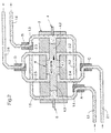
- Figures 1 and 2 show an implementation of the displacement principle. Man recognizes two line strings from the figures, namely one Water line 1.1 to 1.6 and a fuel line 2.1 to 2.6.
- a housing 3 with a piston 4 can also be seen.
- the piston 4 has a partial piston 4.1 of larger diameter and two partial pistons 4.2, 4.3 of smaller diameter.
- the piston 4 is displaceable in a cylinder space in the direction of the arrows in the two figures.
- the dosing device works as follows: In Figure 1, the two-way solenoid valve C is switched such that the fuel line sections 2.1 and 2.2 are in conductive connection with each other. Since fuel under pressure is introduced into the line section 2.1, this pressure acts on the partial piston 4.1. This therefore moves to the left in accordance with the arrow shown in FIG. 1.
- Two-way solenoid valve B is switched in such a way that the line sections 1.5 and 1.6 of the water line are in conductive connection with one another.
- Two-way solenoid valve D is switched in such a way that the line sections 2.5, 2.6 of the fuel line are in conductive connection with one another. Due to the movement of the piston 4, partial flows of fuel and water are now pressed into the line sections 2.6 and 1.6. These line sections are brought together (not shown here). The total current is fed to an emulsifying device, not shown here.
- the water-fuel ratio remains constant. It is determined by the volumes of the piston-cylinder units involved. But you can also through the Changing the opening times of the valves in the water line Change ratio. This can be done continuously (e.g. electronically controlled by polling a power signal), so that any Mixing ratio from 0 to at most that determined by the volume Relationship can be established.
- Figure 2 shows that phase of the dosing device in which the piston 4 moves from its left position to its right position.
- the piston thus constantly executes a reciprocating movement, and indeed caused by the under pressure in the line section 2.1 inflowing fuel, and controlled by the solenoid valves, in the first Line through solenoid valve C.
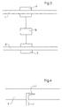
- FIG 3 an embodiment is shown in which the hydrodynamic principle is applied.
- a pump P switched
- the fuel line 2 a turbine T.
- Turbine T and pump P are in drive connection with each other.
- a Gearbox G switched, the translation of which is adjustable.
- This metering device works as follows: In the fuel line 2 is under Fuel under pressure is introduced so that the turbine is driven. The turbine drives the pump P via gearbox G. This sucks accordingly Water from a storage container, not shown, via line 1.
- FIG. 4 illustrates very schematically the application of Ejector principle.
- a nozzle 1.1 is inserted into the fuel line 2, which is part of a water pipe 1.
- the method according to the invention already works when the pressure of the first partial flow in the first line is relatively low. Pressures of 0.5 bar are sufficient. 0.3 bar is also practical. In practice pressures between 0.5 and 1.0 bar will be used.
Landscapes
- Chemical & Material Sciences (AREA)
- Chemical Kinetics & Catalysis (AREA)
- Engineering & Computer Science (AREA)
- Combustion & Propulsion (AREA)
- Mechanical Engineering (AREA)
- General Engineering & Computer Science (AREA)
- Health & Medical Sciences (AREA)
- Public Health (AREA)
- Water Supply & Treatment (AREA)
- Fuel-Injection Apparatus (AREA)
- Jet Pumps And Other Pumps (AREA)
- Nozzles (AREA)
- Treatment Of Fiber Materials (AREA)
- Bakery Products And Manufacturing Methods Therefor (AREA)
- Output Control And Ontrol Of Special Type Engine (AREA)
Description
Dieses treibt wiederum das Pumpenrad an, Demgemäß wird Wasser allein nach Maßgabe des Kraftstoffstromes gefördert. Man könnte hierbei von einem hydrodynamischen System sprechen.
In Figur 1 ist das Zwei-Wege-Magnetventil C derart geschaltet, daß die Kraftstoff-Leitungsabschnitte 2.1 und 2.2 in leitender Verbindung miteinander stehen. Da in den Leitungsabschnitt 2.1 unter Druck stehender Kraftstoff eingeleitet wird, wirkt dieser Druck auf den Teilkolben 4.1. Dieser bewegt sich deshalb entsprechend dem in Figur 1 gezeigten Pfeil nach links.
Zwei-Wege-Magnetventil D ist derart geschaltet, daß die Leitungsabschnitte 2.5, 2.6 der Kraftstoffleitung miteinander in leitender Verbindung stehen. Aufgrund der Bewegung des Kolbens 4 werden nunmehr Teilströme von Kraftstoff und Wasser in die Leitungsabschnitte 2.6 bzw. 1.6 gedrückt. Diese Leitungsabschnitte werden zusammengeführt (hier nicht dargestellt). Der Gesamtstrom wird einem hier nicht dargestellten Emulgiergerät zugeführt.
Es kann nur dann Wasser fließen, wenn auch Kraftstoff fließt. Ferner wird das Mischungsverhältnis zwischen Kraftstoff und Wasser stets konstant gehalten. Eine Überwässerung des resultierenden Gemisches kann somit zu keinem Zeitpunkt eintreten.
Claims (4)
- Emulgieranlage mit einer Dosiervorrichtung, mit den folgenden Merkmalen:a) die Dosiervorrichtung dosiert zwei Teilströme unterschiedlicher Zusammensetzung und bildet somit einen Mischstrom, der eine Emulgiervorrichtung speist;b) es ist eine erste Leitung (2) vorgesehen, die einen ersten, unter Druck stehenden Teilstrom aufnimmt;c) es ist eine zweite Leitung (1) vorgesehen, die an ein Reservoir angeschlossen ist, das seinerseits den zweiten Teilstrom bildet; gekennzeichnet durch die folgenden Merkmale:d) es ist ein Förderelement vorgesehen, das den zweiten Teilstrom fördert, und das seine Energie aus der Strömungsenergie des ersten Teilstromes bezieht.
- Emulgieranlage mit einer Dosiervorrichtung nach Anspruch 1, gekennzeichnet durch die folgenden Merkmale:a) in der zweiten Leitung (1) ist ein Pumpenrad (P) vorgesehen;b) in der ersten Leitung (2) ist ein Turbinenrad (T) vorgesehen;c) Turbinenrad (T) und Pumpenrad (P) stehen in Triebverbindung miteinander.
- Emulgieranlage mit einer Dosiervorrichtung nach Anspruch 2, dadurch gekennzeichnet, daß in der Triebverbindung ein variables Getriebe angeordnet ist.
- Emulgieranlage mit einer Dosiervorrichtung nach Anspruch 1, gekennzeichnet durch die folgenden Merkmale:a) der ersten Leitung ist ein doppelseitig beaufschlagter, erster Kolben zugeordnet;b) es sind Magnetventile vorgesehen, die eine abwechselnde Beaufschlagung des Kolbens mit dem ersten Teilstrom bewirken, und damit eine oszillierende Bewegung des Kolbens;c) der zweiten Leitung ist ein zweiter Kolben zugeordnet, der mit dem ersten Kolben zusammengeschaltet ist und aufgrund von dessen oszillierender Bewegung eine taktweise Verdrängung und Förderung des zweiten Teilstromes bewirkt.
Applications Claiming Priority (2)
| Application Number | Priority Date | Filing Date | Title |
|---|---|---|---|
| DE19819271A DE19819271A1 (de) | 1998-04-30 | 1998-04-30 | Dosiervorrichtung für eine Emulgieranlage |
| DE19819271 | 1998-04-30 |
Publications (2)
| Publication Number | Publication Date |
|---|---|
| EP0953760A1 EP0953760A1 (de) | 1999-11-03 |
| EP0953760B1 true EP0953760B1 (de) | 2001-08-01 |
Family
ID=7866251
Family Applications (1)
| Application Number | Title | Priority Date | Filing Date |
|---|---|---|---|
| EP99108120A Expired - Lifetime EP0953760B1 (de) | 1998-04-30 | 1999-04-24 | Dosiervorrichtung für eine Emulgieranlage |
Country Status (3)
| Country | Link |
|---|---|
| EP (1) | EP0953760B1 (de) |
| AT (1) | ATE203800T1 (de) |
| DE (2) | DE19819271A1 (de) |
Cited By (1)
| Publication number | Priority date | Publication date | Assignee | Title |
|---|---|---|---|---|
| EP2208879A1 (de) | 2009-01-16 | 2010-07-21 | Voith Patent GmbH | Verfahren und Vorrichtung zum Betrieb eines Dieselmotors mit einem Mischkraftstoff |
Family Cites Families (10)
| Publication number | Priority date | Publication date | Assignee | Title |
|---|---|---|---|---|
| JPS5844857B2 (ja) * | 1975-11-07 | 1983-10-05 | トヨタ自動車株式会社 | ミズテンカキコウオユウスル ナイネンキカン |
| DE2906300C2 (de) * | 1978-02-23 | 1984-05-24 | Becton, Dickinson and Co., 07652 Paramus, N.J. | Regelbare Dosiervorrichtung für Flüssigkeiten |
| US4461245A (en) * | 1982-04-13 | 1984-07-24 | Michael Vinokur | Fluid injection system for internal combustion engine |
| DE3611728C1 (de) * | 1986-04-08 | 1987-04-16 | Meinz Hans Willi | Vorrichtung zum Dosieren und Mischen von fliessfaehigen Mehrkomponentensystemen |
| DE3779242D1 (de) * | 1986-10-08 | 1992-06-25 | Zugol Ag | Verfahren und geraet zur erzeugung einer wasser-in-oel-emulsion. |
| DE4137179C2 (de) * | 1991-11-12 | 1997-02-27 | Hdc Ag | Vorrichtung zum Erzeugen einer Wasser-in-Öl Emulsion und Verwendung der Vorrichtung an einem Dieselmotor |
| DE4139782C2 (de) * | 1991-12-03 | 1994-05-19 | Roland Steinmaier | Emulgiervorrichtung zum Emulgieren von Dieselkraftstoff und Wasser |
| DE4235528C2 (de) * | 1992-10-21 | 1994-08-18 | Alfred Schmid Ag Plastikwerk | Vorrichtung zum Dosieren und Mischen von zwei unterschiedlichen, viskosen Massen, insbesondere Dentalmassen |
| DE4323160C1 (de) * | 1993-07-10 | 1995-01-19 | Hilger & Kern Gmbh | Mehrkomponenten-Dosiereinrichtung |
| DE4408392A1 (de) * | 1994-03-12 | 1995-09-28 | Mtu Friedrichshafen Gmbh | Vorrichtung zur Bildung einer Öl-Wasser-Emulsion |
-
1998
- 1998-04-30 DE DE19819271A patent/DE19819271A1/de not_active Withdrawn
-
1999
- 1999-04-24 AT AT99108120T patent/ATE203800T1/de not_active IP Right Cessation
- 1999-04-24 DE DE59900174T patent/DE59900174D1/de not_active Expired - Lifetime
- 1999-04-24 EP EP99108120A patent/EP0953760B1/de not_active Expired - Lifetime
Cited By (1)
| Publication number | Priority date | Publication date | Assignee | Title |
|---|---|---|---|---|
| EP2208879A1 (de) | 2009-01-16 | 2010-07-21 | Voith Patent GmbH | Verfahren und Vorrichtung zum Betrieb eines Dieselmotors mit einem Mischkraftstoff |
Also Published As
| Publication number | Publication date |
|---|---|
| EP0953760A1 (de) | 1999-11-03 |
| DE19819271A1 (de) | 1999-11-11 |
| ATE203800T1 (de) | 2001-08-15 |
| DE59900174D1 (de) | 2001-09-06 |
Similar Documents
| Publication | Publication Date | Title |
|---|---|---|
| DE69227133T2 (de) | Verfahren und Vorrichtung zur Zuführung von Brennstoffemulsion | |
| EP1952006B1 (de) | Vorrichtung zur herstellung einer dieselöl-wasser-mikro- emulsion und zur einspritzung dieser emulsion in einen dieselmotor | |
| DE112008002451B4 (de) | System und Methode zum Dosieren von Treibstoff in einem Hochdruck-Pumpensystem | |
| DE2126736A1 (de) | Kraftstoffeinspntzanlage fur Brenn kraftmaschinen | |
| DE3127831A1 (de) | "system und vorrichtung zum pumpen" | |
| EP0915252A2 (de) | Common-Rail Einspritzsystem | |
| DE3017275A1 (de) | Kraftstoffeinspritzpumpe fuer selbstzuendende brennkraftmaschinen | |
| EP0953760B1 (de) | Dosiervorrichtung für eine Emulgieranlage | |
| EP0007109B1 (de) | Vorrichtung zum Dosieren einer Chemikalienlösung in strömende Frischflüssigkeit | |
| DE10154133C1 (de) | Kraftstoffsystem | |
| EP0400693A2 (de) | Höchstdruckpumpe | |
| EP1361357A2 (de) | Kraftstoffpumpe, insbesondere für eine Brennkraftmaschine mit Direkteinspritzung | |
| DE2422882A1 (de) | Einspritzanlage fuer brennkraftmaschinen | |
| DE3509770A1 (de) | Kraftstoffeinspritzeinheit | |
| DE2644128A1 (de) | Steuereinrichtung fuer ein hydrostatisches getriebe | |
| DE4329407C1 (de) | Verfahren zur Reinigung eines Rußfilters in Abgassystemen einer mit Dieselkraftstoff betriebenen Verbrennungskraftmaschine und Vorrichtung zur Durchführung des Verfahrens | |
| DE1244469B (de) | Kraftstoffeinspritzanlage fuer Brennkraftmaschinen, insbesondere Dieselmotoren, mit einer den Foerderbeginn der Einspritzpumpe aendernden Verstelleinrichtung | |
| DE3928411C2 (de) | ||
| DE102018202825B3 (de) | Vorrichtung und Verfahren zum Fördern von Kraftstoff und Additiv | |
| DE2255986C3 (de) | Pumpeinrichtung für eine Hydraulikanlage in einem Kraftfahrzeug | |
| EP1496243B1 (de) | Verbrennungskraftmaschime | |
| CH616235A5 (en) | Device for testing fuel injection valves. | |
| DE10305783A1 (de) | Kolbenmembranpumpe mit ölseitiger Bedarfssteuerung | |
| DE1576189A1 (de) | Vorrichtung zur Einspritzung von fluessigem Brennstoff fuer Freiflugkolbenmotoren | |
| DE69126220T2 (de) | Pumpe zum mischen |
Legal Events
| Date | Code | Title | Description |
|---|---|---|---|
| PUAI | Public reference made under article 153(3) epc to a published international application that has entered the european phase |
Free format text: ORIGINAL CODE: 0009012 |
|
| 17P | Request for examination filed |
Effective date: 19990813 |
|
| AK | Designated contracting states |
Kind code of ref document: A1 Designated state(s): AT DE FR IT |
|
| AX | Request for extension of the european patent |
Free format text: AL;LT;LV;MK;RO;SI |
|
| 17Q | First examination report despatched |
Effective date: 20000518 |
|
| AKX | Designation fees paid |
Free format text: AT DE FR IT |
|
| GRAG | Despatch of communication of intention to grant |
Free format text: ORIGINAL CODE: EPIDOS AGRA |
|
| GRAG | Despatch of communication of intention to grant |
Free format text: ORIGINAL CODE: EPIDOS AGRA |
|
| GRAH | Despatch of communication of intention to grant a patent |
Free format text: ORIGINAL CODE: EPIDOS IGRA |
|
| GRAH | Despatch of communication of intention to grant a patent |
Free format text: ORIGINAL CODE: EPIDOS IGRA |
|
| GRAA | (expected) grant |
Free format text: ORIGINAL CODE: 0009210 |
|
| AK | Designated contracting states |
Kind code of ref document: B1 Designated state(s): AT DE FR IT |
|
| REF | Corresponds to: |
Ref document number: 203800 Country of ref document: AT Date of ref document: 20010815 Kind code of ref document: T |
|
| REF | Corresponds to: |
Ref document number: 59900174 Country of ref document: DE Date of ref document: 20010906 |
|
| EN | Fr: translation not filed | ||
| EN | Fr: translation not filed |
Free format text: BO 01/52 PAGES: 283, IL Y A LIEU DE SUPPRIMER: LA MENTION DE LA NON REMISE. LA REMISE EST PUBLIEE DANS LE PRESENT BOPI. |
|
| ET | Fr: translation filed | ||
| PLBE | No opposition filed within time limit |
Free format text: ORIGINAL CODE: 0009261 |
|
| STAA | Information on the status of an ep patent application or granted ep patent |
Free format text: STATUS: NO OPPOSITION FILED WITHIN TIME LIMIT |
|
| 26N | No opposition filed | ||
| PGFP | Annual fee paid to national office [announced via postgrant information from national office to epo] |
Ref country code: FR Payment date: 20100428 Year of fee payment: 12 |
|
| PGFP | Annual fee paid to national office [announced via postgrant information from national office to epo] |
Ref country code: IT Payment date: 20100419 Year of fee payment: 12 Ref country code: DE Payment date: 20100526 Year of fee payment: 12 Ref country code: AT Payment date: 20100421 Year of fee payment: 12 |
|
| REG | Reference to a national code |
Ref country code: DE Ref legal event code: R119 Ref document number: 59900174 Country of ref document: DE |
|
| REG | Reference to a national code |
Ref country code: DE Ref legal event code: R119 Ref document number: 59900174 Country of ref document: DE |
|
| REG | Reference to a national code |
Ref country code: AT Ref legal event code: MM01 Ref document number: 203800 Country of ref document: AT Kind code of ref document: T Effective date: 20110424 |
|
| REG | Reference to a national code |
Ref country code: FR Ref legal event code: ST Effective date: 20111230 |
|
| PG25 | Lapsed in a contracting state [announced via postgrant information from national office to epo] |
Ref country code: FR Free format text: LAPSE BECAUSE OF NON-PAYMENT OF DUE FEES Effective date: 20110502 |
|
| PG25 | Lapsed in a contracting state [announced via postgrant information from national office to epo] |
Ref country code: IT Free format text: LAPSE BECAUSE OF NON-PAYMENT OF DUE FEES Effective date: 20110424 Ref country code: AT Free format text: LAPSE BECAUSE OF NON-PAYMENT OF DUE FEES Effective date: 20110424 |
|
| PG25 | Lapsed in a contracting state [announced via postgrant information from national office to epo] |
Ref country code: DE Free format text: LAPSE BECAUSE OF NON-PAYMENT OF DUE FEES Effective date: 20111031 |