EP0953772A1 - Pompe centrifuge avec vis de désaérage - Google Patents
Pompe centrifuge avec vis de désaérage Download PDFInfo
- Publication number
- EP0953772A1 EP0953772A1 EP99108733A EP99108733A EP0953772A1 EP 0953772 A1 EP0953772 A1 EP 0953772A1 EP 99108733 A EP99108733 A EP 99108733A EP 99108733 A EP99108733 A EP 99108733A EP 0953772 A1 EP0953772 A1 EP 0953772A1
- Authority
- EP
- European Patent Office
- Prior art keywords
- screw
- vent screw
- shaft
- pump
- bore
- Prior art date
- Legal status (The legal status is an assumption and is not a legal conclusion. Google has not performed a legal analysis and makes no representation as to the accuracy of the status listed.)
- Granted
Links
- 238000013022 venting Methods 0.000 claims description 4
- 238000001816 cooling Methods 0.000 claims description 3
- 238000009423 ventilation Methods 0.000 abstract 2
- XLYOFNOQVPJJNP-UHFFFAOYSA-N water Substances O XLYOFNOQVPJJNP-UHFFFAOYSA-N 0.000 description 10
- 239000000203 mixture Substances 0.000 description 2
- 238000010276 construction Methods 0.000 description 1
- 239000012530 fluid Substances 0.000 description 1
- 238000007789 sealing Methods 0.000 description 1
Images
Classifications
-
- F—MECHANICAL ENGINEERING; LIGHTING; HEATING; WEAPONS; BLASTING
- F04—POSITIVE - DISPLACEMENT MACHINES FOR LIQUIDS; PUMPS FOR LIQUIDS OR ELASTIC FLUIDS
- F04D—NON-POSITIVE-DISPLACEMENT PUMPS
- F04D9/00—Priming; Preventing vapour lock
- F04D9/001—Preventing vapour lock
-
- F—MECHANICAL ENGINEERING; LIGHTING; HEATING; WEAPONS; BLASTING
- F04—POSITIVE - DISPLACEMENT MACHINES FOR LIQUIDS; PUMPS FOR LIQUIDS OR ELASTIC FLUIDS
- F04D—NON-POSITIVE-DISPLACEMENT PUMPS
- F04D13/00—Pumping installations or systems
- F04D13/02—Units comprising pumps and their driving means
- F04D13/06—Units comprising pumps and their driving means the pump being electrically driven
- F04D13/0606—Canned motor pumps
- F04D13/0626—Details of the can
Definitions
- the invention relates to a centrifugal pump with a Canned tube through which the medium is flowing for cooling is, through a shaft bore the fluid in the pump suction chamber flows back and to vent the A vent screw at the bottom of the can Canned tube is arranged.
- Centrifugal motor pumps are known, their canned space is vented by means of a bleed screw, which on Bottom of the can is screwed in. After opening the vent screw emerges from inside the A water / air mixture.
- a bleed screw which on Bottom of the can is screwed in. After opening the vent screw emerges from inside the A water / air mixture.
- leakage of water does not mean that the pump is complete is vented because when the pump is vented in Suction chamber already has water and air only through the small gap between the shaft and the radial bearing can escape. This allows water to flow through faster the shaft bore in the upper area of the containment shell and the vent screw enters Water / air mixture out, although the pump chamber is not is completely flooded. This is particularly serious if a pump has several hydraulic levels.
- the object of the invention is a pump of the beginning to improve the type mentioned so that it can be clearly identified is whether the hydraulic range of the pump is sufficient is filled with water and that a complete Venting of the pump is guaranteed.
- vent screw in the open state directly or closes the shaft bore via an intermediate part.
- the Vent screw at its inner end a head has in the closed state with a conical rear ring surface on a conical seat of the bore in which the Vent screw is screwed in. It is also sealing via O-ring or flat seal possible.
- the head of the Vent screw with its front on the Rest the shaft end.
- vent screw in a threaded insert lies in the bottom of the Can is attached.
- a simple push of the Bleed screw is reached when the Vent screw on the outside of it Actuation of a polygonal one Hexagon pocket hole has.
- the shaft be vertical stands.
- the centrifugal motor pump can also have several Have pump stages.
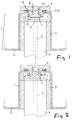
- FIGS. 1 and 2 only the end region 1 is smaller Diameter of the can 2 shown.
- the bearing 3 in which the end of the motor shaft 4 is supported.
- the wave 4 has a coaxial shaft bore 5 through which The inside of the canned pipe for cooling flowing water Pump room can flow back.
- the inside of the canned pipe for cooling flowing water Pump room can flow back.
- the pump builds up water from the Pressure side of the pump through the rotor space and thus through the inside of the can and through a gap between Shaft and radial bearing in the top area of the can and then through the shaft bore 5 back into the not illustrated suction chamber of the impeller that on the other End of the shaft 4 is attached.
- the cup-shaped end region 1 of the can 2 has a coaxial opening 6 with a socket-shaped extension, in attached to a threaded insert 7, in particular is welded or soldered.
- the cross section T-shaped thread insert 7 has a coaxial Threaded bore 8 in which a vent screw 9 is screwed in. Above the bleed screw 9 is the front outer wall of the Motor housing.
- vent screw 9 At the inner end of the vent screw 9 is a head 11 molded on, which forms a conical annular surface 12, the with the vent screw closed on a Taper seat 13 of the threaded insert 7 rests. Will the Vent screw 9 down to the open position screwed, the screw 9 moves in the direction of Face 14 of the shaft 4 and closes the Opening or mouth 15 of the shaft bore 5, as in Fig. 2 shown. As a result, water can no longer escape from the Shaft bore 5 emerge and only air occurs next to the Vent screw 9 upwards.
- the Bleed screw 9 also directly in opening 6 be screwed, especially if the opening 6 a has a smaller diameter. Furthermore, the Vent screw 9 a key surface laterally exhibit.
- the centrifugal motor pump is preferably installed so that the shaft or axis is vertical, the Bleed screw 9 is on top. Preferably owns the pump has several pump stages. Finally, between the head 11 and the upper end of the shaft 4 Be arranged intermediate part, in particular on the head 11th is attached to represent an extension or to achieve greater tightness.
Landscapes
- Engineering & Computer Science (AREA)
- Mechanical Engineering (AREA)
- General Engineering & Computer Science (AREA)
- Structures Of Non-Positive Displacement Pumps (AREA)
Applications Claiming Priority (2)
| Application Number | Priority Date | Filing Date | Title |
|---|---|---|---|
| DE19819690A DE19819690A1 (de) | 1998-05-02 | 1998-05-02 | Kreiselmotorpumpe mit Entlüftungsschraube |
| DE19819690 | 1998-05-02 |
Publications (2)
| Publication Number | Publication Date |
|---|---|
| EP0953772A1 true EP0953772A1 (fr) | 1999-11-03 |
| EP0953772B1 EP0953772B1 (fr) | 2001-02-07 |
Family
ID=7866517
Family Applications (1)
| Application Number | Title | Priority Date | Filing Date |
|---|---|---|---|
| EP99108733A Expired - Lifetime EP0953772B1 (fr) | 1998-05-02 | 1999-04-30 | Pompe centrifuge avec vis de purge |
Country Status (2)
| Country | Link |
|---|---|
| EP (1) | EP0953772B1 (fr) |
| DE (2) | DE19819690A1 (fr) |
Families Citing this family (1)
| Publication number | Priority date | Publication date | Assignee | Title |
|---|---|---|---|---|
| DE102009033111A1 (de) * | 2009-07-15 | 2011-02-03 | Ksb Aktiengesellschaft | Spalttopf |
Citations (3)
| Publication number | Priority date | Publication date | Assignee | Title |
|---|---|---|---|---|
| GB834951A (en) * | 1957-10-28 | 1960-05-11 | Faere Armaturfabrik Ab | Improvements in or relating to electromotor-driven centrifugal pump assemblies |
| GB963993A (en) * | 1960-10-17 | 1964-07-15 | Hollesens Fabrikker As H | Improvements in and relating to electric motor-driven liquid pumps |
| FR1399292A (fr) * | 1964-06-22 | 1965-05-14 | Taco Inc | Pompe |
Family Cites Families (4)
| Publication number | Priority date | Publication date | Assignee | Title |
|---|---|---|---|---|
| DE7523874U (de) * | 1975-07-26 | 1976-08-05 | Wilo-Werk Gmbh & Co - Pumpen - Und Apparatebau, 4600 Dortmund | Stopfbuchsloses pumpenaggregat |
| DE2941133C2 (de) * | 1979-10-10 | 1985-01-31 | Speck-Kolbenpumpen-Fabrik Otto Speck Kg, 8192 Geretsried | Heizungsumwälzpume |
| DE3701562C2 (de) * | 1986-03-12 | 1996-02-08 | Wilo Gmbh | Kreiselpumpe mit Spaltrohrmotor |
| DE4208829C2 (de) * | 1992-03-19 | 1995-04-27 | Wilo Gmbh | Spaltrohrmotorpumpe |
-
1998
- 1998-05-02 DE DE19819690A patent/DE19819690A1/de not_active Withdrawn
-
1999
- 1999-04-30 EP EP99108733A patent/EP0953772B1/fr not_active Expired - Lifetime
- 1999-04-30 DE DE59900040T patent/DE59900040D1/de not_active Expired - Lifetime
Patent Citations (3)
| Publication number | Priority date | Publication date | Assignee | Title |
|---|---|---|---|---|
| GB834951A (en) * | 1957-10-28 | 1960-05-11 | Faere Armaturfabrik Ab | Improvements in or relating to electromotor-driven centrifugal pump assemblies |
| GB963993A (en) * | 1960-10-17 | 1964-07-15 | Hollesens Fabrikker As H | Improvements in and relating to electric motor-driven liquid pumps |
| FR1399292A (fr) * | 1964-06-22 | 1965-05-14 | Taco Inc | Pompe |
Also Published As
| Publication number | Publication date |
|---|---|
| DE59900040D1 (de) | 2001-03-15 |
| EP0953772B1 (fr) | 2001-02-07 |
| DE19819690A1 (de) | 1999-11-04 |
Similar Documents
| Publication | Publication Date | Title |
|---|---|---|
| DE69612535T2 (de) | Vorgesteuertes Fluidumventil | |
| EP0715692B1 (fr) | Soupape de protection de pompe | |
| DE69725375T2 (de) | Federspannzylinder | |
| EP3364043B1 (fr) | Groupe motopompe avec dispositif de purge d'air et de vidange intégré | |
| EP3135829A1 (fr) | Armature sanitaire antigel et son procédé d'arrêt et d'aération | |
| EP0953772B1 (fr) | Pompe centrifuge avec vis de purge | |
| DE69906440T2 (de) | Toilettenspülkasten mit induzierter Luft | |
| EP2142281B1 (fr) | Dispositif de séparation de liquide et système de réservoir équipé d'un dispositif de séparation de liquide | |
| DE4320826C2 (de) | Selbsttätiges Ventil | |
| DE2047815A1 (de) | Entlüftungsventil | |
| EP1223118A1 (fr) | Vanne pour le soufflage d' air comprimé par impulsion pour éliminer les amas de materiau | |
| EP3658803A1 (fr) | Soupape à double siège ayant une membrane | |
| DE3545658A1 (de) | Hydrodynamische bremse fuer ein fahrzeug | |
| DE2113602A1 (de) | Absperrorgan mit druckentlastetem Verschlussorgan | |
| DE3707803C2 (fr) | ||
| DE8033114U1 (de) | Rueckschlagventil | |
| EP1544453B1 (fr) | Vanne ventilée pour vidange d'eau | |
| DE102005041437A1 (de) | Betankungswächter | |
| EP1223117B1 (fr) | Dispositif de type canon à air comprimé pour éliminer les amas de matériau | |
| AT379669B (de) | Absperrschieber mit im normalen betrieb unverschiebbarer spindel | |
| EP1503121A1 (fr) | Soupape pour la rupture de tuyaux | |
| DE102005005452A1 (de) | Systemtrenner | |
| DE202017003786U1 (de) | Ventilanordnung und Ventilbaugruppe | |
| DE29619824U1 (de) | Freilaufrückschlagventil | |
| DE69024823T2 (de) | Kompakte mehrstufige entspanner |
Legal Events
| Date | Code | Title | Description |
|---|---|---|---|
| PUAI | Public reference made under article 153(3) epc to a published international application that has entered the european phase |
Free format text: ORIGINAL CODE: 0009012 |
|
| 17P | Request for examination filed |
Effective date: 19990806 |
|
| AK | Designated contracting states |
Kind code of ref document: A1 Designated state(s): DE FR GB IT |
|
| AX | Request for extension of the european patent |
Free format text: AL;LT;LV;MK;RO;SI |
|
| RIN1 | Information on inventor provided before grant (corrected) |
Inventor name: RUECKWARDT,HELMUT Inventor name: GORONZY, BERND |
|
| GRAG | Despatch of communication of intention to grant |
Free format text: ORIGINAL CODE: EPIDOS AGRA |
|
| AKX | Designation fees paid |
Free format text: DE FR GB IT |
|
| GRAG | Despatch of communication of intention to grant |
Free format text: ORIGINAL CODE: EPIDOS AGRA |
|
| GRAH | Despatch of communication of intention to grant a patent |
Free format text: ORIGINAL CODE: EPIDOS IGRA |
|
| 17Q | First examination report despatched |
Effective date: 20000710 |
|
| RTI1 | Title (correction) |
Free format text: CENTRIFUGAL PUMP WITH BLEED SCREW |
|
| GRAH | Despatch of communication of intention to grant a patent |
Free format text: ORIGINAL CODE: EPIDOS IGRA |
|
| GRAA | (expected) grant |
Free format text: ORIGINAL CODE: 0009210 |
|
| AK | Designated contracting states |
Kind code of ref document: B1 Designated state(s): DE FR GB IT |
|
| GBT | Gb: translation of ep patent filed (gb section 77(6)(a)/1977) |
Effective date: 20010207 |
|
| REF | Corresponds to: |
Ref document number: 59900040 Country of ref document: DE Date of ref document: 20010315 |
|
| ET | Fr: translation filed | ||
| ITF | It: translation for a ep patent filed | ||
| PLBE | No opposition filed within time limit |
Free format text: ORIGINAL CODE: 0009261 |
|
| STAA | Information on the status of an ep patent application or granted ep patent |
Free format text: STATUS: NO OPPOSITION FILED WITHIN TIME LIMIT |
|
| REG | Reference to a national code |
Ref country code: GB Ref legal event code: IF02 |
|
| 26N | No opposition filed | ||
| PGFP | Annual fee paid to national office [announced via postgrant information from national office to epo] |
Ref country code: GB Payment date: 20140430 Year of fee payment: 16 |
|
| PGFP | Annual fee paid to national office [announced via postgrant information from national office to epo] |
Ref country code: FR Payment date: 20140409 Year of fee payment: 16 Ref country code: DE Payment date: 20140430 Year of fee payment: 16 Ref country code: IT Payment date: 20140408 Year of fee payment: 16 |
|
| REG | Reference to a national code |
Ref country code: DE Ref legal event code: R119 Ref document number: 59900040 Country of ref document: DE |
|
| GBPC | Gb: european patent ceased through non-payment of renewal fee |
Effective date: 20150430 |
|
| PG25 | Lapsed in a contracting state [announced via postgrant information from national office to epo] |
Ref country code: IT Free format text: LAPSE BECAUSE OF NON-PAYMENT OF DUE FEES Effective date: 20150430 Ref country code: DE Free format text: LAPSE BECAUSE OF NON-PAYMENT OF DUE FEES Effective date: 20151103 Ref country code: GB Free format text: LAPSE BECAUSE OF NON-PAYMENT OF DUE FEES Effective date: 20150430 |
|
| REG | Reference to a national code |
Ref country code: FR Ref legal event code: ST Effective date: 20151231 |
|
| PG25 | Lapsed in a contracting state [announced via postgrant information from national office to epo] |
Ref country code: FR Free format text: LAPSE BECAUSE OF NON-PAYMENT OF DUE FEES Effective date: 20150430 |