EP0953773B1 - Pompe à liquides en particulier pour le circuit de refroidissement d'un moteur à combustion interne - Google Patents
Pompe à liquides en particulier pour le circuit de refroidissement d'un moteur à combustion interne Download PDFInfo
- Publication number
- EP0953773B1 EP0953773B1 EP19990108411 EP99108411A EP0953773B1 EP 0953773 B1 EP0953773 B1 EP 0953773B1 EP 19990108411 EP19990108411 EP 19990108411 EP 99108411 A EP99108411 A EP 99108411A EP 0953773 B1 EP0953773 B1 EP 0953773B1
- Authority
- EP
- European Patent Office
- Prior art keywords
- duct
- outlet duct
- pump according
- liquid
- outlet
- Prior art date
- Legal status (The legal status is an assumption and is not a legal conclusion. Google has not performed a legal analysis and makes no representation as to the accuracy of the status listed.)
- Expired - Lifetime
Links
Images


Classifications
-
- F—MECHANICAL ENGINEERING; LIGHTING; HEATING; WEAPONS; BLASTING
- F01—MACHINES OR ENGINES IN GENERAL; ENGINE PLANTS IN GENERAL; STEAM ENGINES
- F01P—COOLING OF MACHINES OR ENGINES IN GENERAL; COOLING OF INTERNAL-COMBUSTION ENGINES
- F01P7/00—Controlling of coolant flow
- F01P7/14—Controlling of coolant flow the coolant being liquid
- F01P7/16—Controlling of coolant flow the coolant being liquid by thermostatic control
- F01P7/161—Controlling of coolant flow the coolant being liquid by thermostatic control by bypassing pumps
-
- F—MECHANICAL ENGINEERING; LIGHTING; HEATING; WEAPONS; BLASTING
- F04—POSITIVE - DISPLACEMENT MACHINES FOR LIQUIDS; PUMPS FOR LIQUIDS OR ELASTIC FLUIDS
- F04D—NON-POSITIVE-DISPLACEMENT PUMPS
- F04D15/00—Control, e.g. regulation, of pumps, pumping installations or systems
- F04D15/0005—Control, e.g. regulation, of pumps, pumping installations or systems by using valves
- F04D15/0011—Control, e.g. regulation, of pumps, pumping installations or systems by using valves by-pass valves
-
- F—MECHANICAL ENGINEERING; LIGHTING; HEATING; WEAPONS; BLASTING
- F04—POSITIVE - DISPLACEMENT MACHINES FOR LIQUIDS; PUMPS FOR LIQUIDS OR ELASTIC FLUIDS
- F04D—NON-POSITIVE-DISPLACEMENT PUMPS
- F04D15/00—Control, e.g. regulation, of pumps, pumping installations or systems
- F04D15/0005—Control, e.g. regulation, of pumps, pumping installations or systems by using valves
- F04D15/0016—Control, e.g. regulation, of pumps, pumping installations or systems by using valves mixing-reversing- or deviation valves
-
- F—MECHANICAL ENGINEERING; LIGHTING; HEATING; WEAPONS; BLASTING
- F01—MACHINES OR ENGINES IN GENERAL; ENGINE PLANTS IN GENERAL; STEAM ENGINES
- F01P—COOLING OF MACHINES OR ENGINES IN GENERAL; COOLING OF INTERNAL-COMBUSTION ENGINES
- F01P2025/00—Measuring
- F01P2025/08—Temperature
- F01P2025/32—Engine outcoming fluid temperature
-
- F—MECHANICAL ENGINEERING; LIGHTING; HEATING; WEAPONS; BLASTING
- F01—MACHINES OR ENGINES IN GENERAL; ENGINE PLANTS IN GENERAL; STEAM ENGINES
- F01P—COOLING OF MACHINES OR ENGINES IN GENERAL; COOLING OF INTERNAL-COMBUSTION ENGINES
- F01P2070/00—Details
Definitions
- the present invention relates to a pump for liquids, in particular for the cooling circuit of an internal combustion engine.
- the subject of the invention is a pump which includes a casing with an inlet duct and a (first) outlet duct for the liquid and a chamber defined between them in which a bladed impeller is mounted for rotation, operable to cause a flow of liquid from the inlet duct to the outlet duct.
- Cooling systems for internal combustion engines have been proposed which include a hydraulic circuit with a variable-flow electric pump, a radiator connected to the engine, a by-pass duct which is essentially parallel to the radiator, an automatic valve for regulating the ratio between the flows of liquid fed to the engine through the radiator and through the by-pass duct respectively, and a control unit operable to control the pump so as to vary the flow in dependence on the temperature of the liquid flowing through the circuit, as measured by a sensor.
- a cooling system is known e.g. from JP 57 002417 A.
- One object of the invention is to provide a pump for a cooling system of the aforesaid type, which enables the hydraulic connections required between the components of the system to be radically simplified, and which significantly improves the reliability of the system.
- an internal combustion engine of a motor vehicle for example, is indicated E.
- a cooling system is associated with the said engine.
- This system comprises a hydraulic circuit for supplying a flow of cooling liquid to the engine E.
- the cooling liquid can be a mixture of water and anti-freeze and anti-corrosion agents, for example.
- the hydraulic cooling circuit includes a pumping assembly generally indicated 1, which includes an electric pump 2, of a rotary type, the flow thereof being variable in dependence on variation in the speed of rotation of the impeller.
- the assembly 1 also includes an outlet distributor device 3 connected to the outlet or delivery 2b of the electric pump 2.
- the inlet 2a of the electric pump 2 is connected to an outlet 4 for the coolant liquid of the engine E.
- a radiator (a liquid/air heat exchanger), is indicated 5 with the inlet thereof connected to an outlet duct 3b of the outlet distributor device 3.
- This outlet duct 3b is able to communicate with the intake duct 2a of the electric pump 2 by means of a by-pass duct or passage 8 and a regulating valve 9.
- the outlet of the radiator 5 is connected to an inlet 6 for the coolant liquid of the engine E.
- a by-pass duct, indicated 7, is connected in parallel with the radiator 5, between an outlet duct 3a of the distributor 3 and the inlet 6 of the engine E.
- the duct 3a is in permanent communication with the outlet or delivery 2b of the pump 2.
- the by-pass duct 7 could extend through a heat exchanger (not illustrated), for heating the air flowing into the passenger compartment of the vehicle, for example.
- an electric temperature sensor is indicated 11.
- the sensor 11 is arranged near the inlet 6 for coolant liquid for the engine E.
- This temperature sensor could be arranged elsewhere, for example adjacent the outlet 4 of the engine E, or inside the engine E or at another predetermined point along the fluid circuit carrying the coolant.
- the temperature sensor 11 is connected to an electronic control unit, indicated 12.
- This unit 12 is connected to the electric motor which drives the pump 2, and is operable to control the said pump so that the delivery thereof varies according to predetermined instructions in dependence on the temperature measured by the sensor 11.
- the regulation valve 9 is operable to modify the ratio of the flows of coolant liquid supplied to the engine E through the radiator 5 and through the by-pass duct 7 respectively.
- the pump assembly 1 includes an electric pump 2, driven by an electric motor 10
- the electric pump 2 comprises a spiral casing, generally indicated 13, which is preferably moulded in one piece from plastics material.
- the inlet duct 2a of the electric pump 2 is formed in the upper portion of the spiral casing 13 of the electric pump 2. This duct opens (see Figure 3) into an inner chamber 14 of the spiral casing 13 in which an impeller 15 having a plurality of angularly spaced blades 16 is mounted for rotation.
- the chamber 14 has an outlet aperture or peripheral passage 2b, formed in one piece with the spiral casing 13 and to which the outlet duct 3a is connected.
- this outlet duct is inclined upwardly, so as to extend upwardly from the outlet of the pumping chamber 14 to the level of the inlet duct 2a of the spiral casing.
- the second outlet duct 3b opens off a side portion of the outlet duct 3a and extends essentially perpendicular thereto.
- a control chamber 17, which is essentially cylindrical in the embodiment illustrated, is formed in such a way that the lateral wall thereof is essentially tangential to the wall of the inlet duct 2a (see Figures 3 and 4 in particular).
- the chamber 17 is aligned axially with the outlet duct 3b and opens into the outlet duct 3a, facing the opening of the duct 3b.
- control chamber 17 communicates with the inlet duct 2a through an aperture or slot, indicated 8 in Figures 2 to 4, formed in the region of tangency between their walls.
- regulating valve means 9 are associated with the duct 3b.
- the valve means 9 are sensitive to the difference in pressure between the outlet duct 3a and the inlet duct 2a of the spiral casing, and are prearranged to allow liquid to flow through the outlet duct 3b (and thus through the radiator 5) once this pressure difference is greater than a predetermined value.
- the regulating valve means 9 include a valve member 20 able to cooperate, substantially as a shutter, with the opening of the outlet duct 3b.
- This valve member 20 is connected by a rod 21 to a piston 22 sealingly slidably mounted in the portion of the control chamber 17 downstream of the passage 8.
- the piston 22 is subject on one side to the pressure of the liquid flowing into the control chamber 17 from the inlet duct 2a, through the by-pass passage 8. On the other side, the piston 22 is subject to the pressure of the liquid flowing through the outlet duct 3a.
- a spring 23 is interposed between the valve member 20 and a stop 24 formed in the outlet duct 3b. This spring 23 tends to maintain the valve member 20 engaged against the mouth or entrance of the duct 3b.
- valve member 20 closes the opening of the duct 3b.
- the control unit 12 controls the electric pump to rotate at a moderate speed of rotation, whereby the pressure difference acting on the opposite sides of the piston 22 is not sufficient to overcome the action of the spring 23. Under these conditions, the pump 2 causes coolant liquid to flow to the engine E through the by-pass duct 7 alone.
- the control unit 12 shifts the electric pump 2 to a speed of rotation at which the pressure difference acting on the opposite sides of the piston 22 causes this latter to move whereby the valve 20 moves away from the opening of the outlet duct 3b. Under this condition, a portion of the liquid flowing from the electric pump 2 enters the outlet duct 3b and flows through the radiator 5. Therefore, a mixed flow of relatively cold liquid, from the radiator 5, and relatively warm liquid, from the by-pass duct 7, reaches the inlet 6 of the engine E.
- the control unit 12 is set to control the speed of rotation of the pump 2 so as to regulate the temperature of the fluid supplied to the engine E in the desired manner.
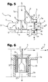
- FIG. 5 shows a variant of the pumping assembly 1, and in particular the spiral casing 13.
- parts and elements that have already been described are indicated once again by the same numbers.
- the by-pass passage 8 is constituted by a duct which is inclined to the axis of the inlet duct 2a and extends towards the outlet duct 3a. This arrangement enables the outlet duct 3a to be maintained substantially on the same plane as the chamber of the impeller 15. If the inclination is right, the by-pass duct 8 can be formed in one piece with the spiral casing 13.
- FIG. 6 shows an alternative embodiment of the valve 20.
- the valve 20 not only acts as a shutter but is able to increase the flow of liquid through the outlet duct 3b at a predetermined rate as it moves away from the associated opening of the duct 3b.
- the valve 20 has an essentially cylindrical sleeve 25, closed at the top by a transverse wall 26.
- the side wall of the sleeve 25, which extends into the duct 3b one or more apertures 27 are formed, shaped so as to allow a gradual increase of the flow of liquid into the duct 3b during the upward movement of the valve member 20.
Landscapes
- Engineering & Computer Science (AREA)
- Mechanical Engineering (AREA)
- General Engineering & Computer Science (AREA)
- Chemical & Material Sciences (AREA)
- Combustion & Propulsion (AREA)
- Structures Of Non-Positive Displacement Pumps (AREA)
- Lubrication Of Internal Combustion Engines (AREA)
Claims (9)
- Pompe (1) à liquides, en particulier pour le circuit de refroidissement (CS) d'un moteur à combustion interne (E), qui comprend un corps de pompe à volute (13) muni d'une conduite d'arrivée (2a) et d'une première conduite de sortie (3a) pour le liquide, entre lesquelles est définie une chambre (14) dans laquelle une roue à aubes (15) est montée de façon à pouvoir entrer en rotation pour créer un flux de liquide de la conduite d'arrivée (2a) vers ladite conduite de sortie (3a) ;
caractérisée en ce qu'une seconde conduite de sortie (3b) s'embranche sur la première conduite de sortie (3a), un dispositif à soupape (9) étant associé à la seconde conduite de sortie (3b), lequel dispositif à soupape est sensible à la différence de pression entre la première conduite de sortie (3a) et la conduite d'arrivée (2a) et peut être actionné de manière à permettre au liquide de s'écouler par ladite seconde conduite d'arrivée (3b), en fonction de ladite différence de pression. - Pompe selon la revendication 1, caractérisée en ce qu'un canal de dérivation (8) est formé dans le corps de pompe à volute (13), entre la conduite d'arrivée (2a) et une chambre de contrôle (17) formée sur un plan adjacent à la première conduite de sortie (3a) et située en face de l'ouverture de la seconde conduite de sortie susmentionnée (3b) ; ledit dispositif à soupape (9) comprend une soupape (20) destinée à réguler le flux, laquelle agit avec l'ouverture de la seconde conduite de sortie (3b), est reliée à un piston (22) monté de manière à pouvoir coulisser dans ladite chambre de contrôle (17) et est soumise, à une extrémité, à la pression du liquide s'écoulant via le canal de dérivation (8) dans ladite chambre de contrôle (17) et, à l'autre extrémité, à la pression du liquide s'écoulant par la première conduite de sortie (a).
- Pompe selon la revendication 2, caractérisée en ce que la soupape de régulation (20) est reliée par une tige (21) au piston associé (22).
- Pompe selon la revendication 2 ou 3, caractérisée en ce que ledit dispositif à soupape de régulation (9) comprend un élément de charge initiale élastique (23) qui tend à maintenir ledit dispositif à soupape (9) dans une position permettant à un minimum de liquidé de s'écouler par ladite seconde conduite de sortie (3b).
- Pompe selon l'une quelconque des revendications 2 à 4, caractérisée en ce que ladite soupape de régulation (20) comprend un obturateur agissant avec le bord de l'ouverture de la seconde conduite d'arrivée (3b), lequel sert de siège de soupape.
- Pompe selon la revendication 5, caractérisée en ce que ladite soupape de régulation (20) est formée de telle manière qu'elle s'écarte dudit siège, ce qui permet d'augmenter l'apport de liquide par la seconde conduite de sortie (3b), lequel varie en fonction d'un schéma déterminé.
- Pompe selon l'une quelconque des revendications 2 à 6, caractérisée en ce que la première conduite de sortie (3a) est inclinée au moins partiellement et s'étend de la chambre (14) de la roue (15) jusqu'au niveau de la conduite d'arrivée (2a) du corps de pompe à volute (13), et en ce que la paroi de ladite chambre de contrôle (17) est essentiellement tangentielle à la paroi de ladite conduite d'arrivée (2a) ; une ouverture (8) est formée dans la zone où lesdites parois se rejoignent, constituant ledit canal de dérivation.
- Pompe selon l'une quelconque des revendications 2 à 6, caractérisée en ce que le canal de dérivation (8) est constitué d'une conduite inclinée vers l'axe de la conduite d'arrivée (2a) du corps de pompe à volute (13) et menant vers ladite première conduite de sortie (3a).
- Pompe selon la revendication 8, caractérisée en ce que la conduite de dérivation inclinée (8) s'étend dans une direction qui croise ladite première conduite de sortie (3a).
Applications Claiming Priority (2)
| Application Number | Priority Date | Filing Date | Title |
|---|---|---|---|
| IT98TO000371A ITTO980371A1 (it) | 1998-04-30 | 1998-04-30 | Pompa per liquidi, particolarmente per un circuito di raffreddamento d i un motore a combustione interna. |
| ITTO980371 | 1998-04-30 |
Publications (2)
| Publication Number | Publication Date |
|---|---|
| EP0953773A1 EP0953773A1 (fr) | 1999-11-03 |
| EP0953773B1 true EP0953773B1 (fr) | 2004-08-18 |
Family
ID=11416725
Family Applications (1)
| Application Number | Title | Priority Date | Filing Date |
|---|---|---|---|
| EP19990108411 Expired - Lifetime EP0953773B1 (fr) | 1998-04-30 | 1999-04-29 | Pompe à liquides en particulier pour le circuit de refroidissement d'un moteur à combustion interne |
Country Status (3)
| Country | Link |
|---|---|
| EP (1) | EP0953773B1 (fr) |
| DE (1) | DE69919437T2 (fr) |
| IT (1) | ITTO980371A1 (fr) |
Families Citing this family (8)
| Publication number | Priority date | Publication date | Assignee | Title |
|---|---|---|---|---|
| US7156617B2 (en) * | 2004-09-08 | 2007-01-02 | Attwood Corporation | Dual outlet port pump |
| WO2007019496A1 (fr) * | 2005-08-08 | 2007-02-15 | Cooper-Standard Automotive, Inc. | Passage de derivation pour pompe a fluide |
| DE102009007695A1 (de) * | 2009-02-05 | 2010-08-12 | Mahle International Gmbh | Kühlsystem in einem Kraftfahrzeug |
| US8979474B2 (en) * | 2009-06-25 | 2015-03-17 | Tbk Co., Ltd. | Variable flow rate pump |
| DE102013224005A1 (de) * | 2013-11-25 | 2015-05-28 | Volkswagen Aktiengesellschaft | Kühlsystem |
| EP2993354A1 (fr) * | 2014-09-05 | 2016-03-09 | Valter Papaveri | Pompe de turbine centrifuge à basse température afin de verser des combustibles liquides en général |
| DE102017200876A1 (de) * | 2016-11-14 | 2018-05-17 | Mahle International Gmbh | Elektrische Kühlmittelpumpe |
| CN116291843B (zh) * | 2022-12-29 | 2023-11-24 | 盐城海纳汽车零部件有限公司 | 一种发动机冷却水泵装置 |
Family Cites Families (4)
| Publication number | Priority date | Publication date | Assignee | Title |
|---|---|---|---|---|
| FR2455174A2 (fr) * | 1979-04-23 | 1980-11-21 | Sev Marchal | Dispositif de regulation de la temperature du liquide de refroidissement pour moteur a combustion interne |
| JPS572417A (en) * | 1980-06-06 | 1982-01-07 | Yamaha Motor Co Ltd | Motorcycle |
| US4753570A (en) * | 1986-10-14 | 1988-06-28 | Whirlpool Corporation | Bidirectional pump with diaphragm operated valve for dishwasher |
| JPH0255824A (ja) * | 1988-08-22 | 1990-02-26 | Aisan Ind Co Ltd | 車両用冷却水ポンプ |
-
1998
- 1998-04-30 IT IT98TO000371A patent/ITTO980371A1/it unknown
-
1999
- 1999-04-29 EP EP19990108411 patent/EP0953773B1/fr not_active Expired - Lifetime
- 1999-04-29 DE DE69919437T patent/DE69919437T2/de not_active Expired - Fee Related
Also Published As
| Publication number | Publication date |
|---|---|
| ITTO980371A1 (it) | 1999-10-30 |
| DE69919437D1 (de) | 2004-09-23 |
| DE69919437T2 (de) | 2005-01-20 |
| EP0953773A1 (fr) | 1999-11-03 |
Similar Documents
| Publication | Publication Date | Title |
|---|---|---|
| US5975031A (en) | Cooling system for an internal combustion engine, particularly for motor vehicles | |
| US6976505B2 (en) | Valve control system for distributing and regulating the flow of coolant | |
| US5657722A (en) | System for maintaining engine oil at a desired temperature | |
| US4930455A (en) | Controlling engine coolant flow and valve assembly therefor | |
| JP2636318B2 (ja) | 液圧駆動式冷却ファンの制御装置 | |
| EP1537308B1 (fr) | Systemes de refroidissement pour moteurs | |
| US6309193B1 (en) | Coolant pump for automotive use | |
| EP0953773A1 (fr) | Pompe à liquides en particulier pour le circuit de refroidissement d'un moteur à combustion interne | |
| US6499963B2 (en) | Coolant pump for automotive use | |
| US4011988A (en) | Device for controlling the flow of cooling water in an internal combustion engine | |
| US5787845A (en) | Combined bypass and thermostat assembly | |
| CA2209792C (fr) | Systeme pour maintenir de l'huile moteur a une temperature optimale | |
| US20190323413A1 (en) | Coolant pump for vehicle, cooling system provided with the same and control method for the same | |
| JP2825861B2 (ja) | 水冷式インタークーラ付内燃機関 | |
| JP4417644B2 (ja) | 車両冷却装置 | |
| EP0343785A2 (fr) | Systèmes de refroidissement | |
| EP0020563B1 (fr) | Appareil moteur a soupape pour systeme d'entrainement hydraulique de ventilateur | |
| CA1306395C (fr) | Regulation de debit de fluide de refroidissement de moteur, et soupape servant a assurer cette regulation | |
| WO1996025591A1 (fr) | Systeme pour maintenir de l'huile moteur a une temperature optimale | |
| JPH085326Y2 (ja) | 気化器の加温装置 | |
| EP1074509A1 (fr) | Soupape secondaire | |
| EP0442307A2 (fr) | Compensation des variations de vitesse pour une pompe à eau dans un système de conditionnement d'air pour l'habitacle d'un véhicule automobile | |
| KR20000006402U (ko) | 자동차용 기화기의 드로틀 바디 | |
| CS257189B1 (cs) | Zařízení pro regulaci chlazení pro vzduchem chlazené spalovací motory | |
| JP2000213348A (ja) | エンジンの冷却装置 |
Legal Events
| Date | Code | Title | Description |
|---|---|---|---|
| PUAI | Public reference made under article 153(3) epc to a published international application that has entered the european phase |
Free format text: ORIGINAL CODE: 0009012 |
|
| AK | Designated contracting states |
Kind code of ref document: A1 Designated state(s): DE FR GB IT |
|
| AX | Request for extension of the european patent |
Free format text: AL;LT;LV;MK;RO;SI |
|
| 17P | Request for examination filed |
Effective date: 20000418 |
|
| AKX | Designation fees paid |
Free format text: DE FR GB IT |
|
| GRAP | Despatch of communication of intention to grant a patent |
Free format text: ORIGINAL CODE: EPIDOSNIGR1 |
|
| GRAS | Grant fee paid |
Free format text: ORIGINAL CODE: EPIDOSNIGR3 |
|
| RAP1 | Party data changed (applicant data changed or rights of an application transferred) |
Owner name: GATE S.R.L. |
|
| GRAA | (expected) grant |
Free format text: ORIGINAL CODE: 0009210 |
|
| AK | Designated contracting states |
Kind code of ref document: B1 Designated state(s): DE FR GB IT |
|
| PG25 | Lapsed in a contracting state [announced via postgrant information from national office to epo] |
Ref country code: IT Free format text: LAPSE BECAUSE OF FAILURE TO SUBMIT A TRANSLATION OF THE DESCRIPTION OR TO PAY THE FEE WITHIN THE PRE;WARNING: LAPSES OF ITALIAN PATENTS WITH EFFECTIVE DATE BEFORE 2007 MAY HAVE OCCURRED AT ANY TIME BEFORE 2007. THE CORRECT EFFECTIVE DATE MAY BE DIFFERENT FROM THE ONE RECORDED.SCRIBED TIME-LIMIT Effective date: 20040818 |
|
| REG | Reference to a national code |
Ref country code: GB Ref legal event code: FG4D |
|
| REF | Corresponds to: |
Ref document number: 69919437 Country of ref document: DE Date of ref document: 20040923 Kind code of ref document: P |
|
| ET | Fr: translation filed | ||
| PLBE | No opposition filed within time limit |
Free format text: ORIGINAL CODE: 0009261 |
|
| STAA | Information on the status of an ep patent application or granted ep patent |
Free format text: STATUS: NO OPPOSITION FILED WITHIN TIME LIMIT |
|
| 26N | No opposition filed |
Effective date: 20050519 |
|
| PGFP | Annual fee paid to national office [announced via postgrant information from national office to epo] |
Ref country code: GB Payment date: 20080320 Year of fee payment: 10 |
|
| PGFP | Annual fee paid to national office [announced via postgrant information from national office to epo] |
Ref country code: DE Payment date: 20080320 Year of fee payment: 10 |
|
| GBPC | Gb: european patent ceased through non-payment of renewal fee |
Effective date: 20090429 |
|
| REG | Reference to a national code |
Ref country code: FR Ref legal event code: ST Effective date: 20091231 |
|
| PG25 | Lapsed in a contracting state [announced via postgrant information from national office to epo] |
Ref country code: DE Free format text: LAPSE BECAUSE OF NON-PAYMENT OF DUE FEES Effective date: 20091103 |
|
| PG25 | Lapsed in a contracting state [announced via postgrant information from national office to epo] |
Ref country code: GB Free format text: LAPSE BECAUSE OF NON-PAYMENT OF DUE FEES Effective date: 20090429 Ref country code: FR Free format text: LAPSE BECAUSE OF NON-PAYMENT OF DUE FEES Effective date: 20091222 |
|
| PGFP | Annual fee paid to national office [announced via postgrant information from national office to epo] |
Ref country code: FR Payment date: 20080430 Year of fee payment: 10 |