EP0953794B1 - Soupape à cartouche pneumatique - Google Patents
Soupape à cartouche pneumatique Download PDFInfo
- Publication number
- EP0953794B1 EP0953794B1 EP99303247A EP99303247A EP0953794B1 EP 0953794 B1 EP0953794 B1 EP 0953794B1 EP 99303247 A EP99303247 A EP 99303247A EP 99303247 A EP99303247 A EP 99303247A EP 0953794 B1 EP0953794 B1 EP 0953794B1
- Authority
- EP
- European Patent Office
- Prior art keywords
- valve
- valve body
- air
- exhaust
- piston
- Prior art date
- Legal status (The legal status is an assumption and is not a legal conclusion. Google has not performed a legal analysis and makes no representation as to the accuracy of the status listed.)
- Expired - Lifetime
Links
- 238000007789 sealing Methods 0.000 claims description 40
- 125000006850 spacer group Chemical group 0.000 claims description 27
- 239000000463 material Substances 0.000 claims description 2
- 229920003023 plastic Polymers 0.000 claims description 2
- 239000004033 plastic Substances 0.000 claims description 2
- 230000007246 mechanism Effects 0.000 description 7
- 238000010276 construction Methods 0.000 description 3
- 239000002184 metal Substances 0.000 description 2
- 229920004943 Delrin® Polymers 0.000 description 1
- 229930040373 Paraformaldehyde Natural products 0.000 description 1
- 239000011521 glass Substances 0.000 description 1
- 229920002492 poly(sulfone) Polymers 0.000 description 1
- -1 polyoxymethylene Polymers 0.000 description 1
- 229920006324 polyoxymethylene Polymers 0.000 description 1
- 238000003466 welding Methods 0.000 description 1
Images




Classifications
-
- C—CHEMISTRY; METALLURGY
- C03—GLASS; MINERAL OR SLAG WOOL
- C03B—MANUFACTURE, SHAPING, OR SUPPLEMENTARY PROCESSES
- C03B9/00—Blowing glass; Production of hollow glass articles
- C03B9/30—Details of blowing glass; Use of materials for the moulds
- C03B9/40—Gearing or controlling mechanisms specially adapted for glass-blowing machines
- C03B9/403—Hydraulic or pneumatic systems
- C03B9/406—Manifolds or regulating devices, e.g. valves
-
- F—MECHANICAL ENGINEERING; LIGHTING; HEATING; WEAPONS; BLASTING
- F16—ENGINEERING ELEMENTS AND UNITS; GENERAL MEASURES FOR PRODUCING AND MAINTAINING EFFECTIVE FUNCTIONING OF MACHINES OR INSTALLATIONS; THERMAL INSULATION IN GENERAL
- F16K—VALVES; TAPS; COCKS; ACTUATING-FLOATS; DEVICES FOR VENTING OR AERATING
- F16K11/00—Multiple-way valves, e.g. mixing valves; Pipe fittings incorporating such valves
- F16K11/02—Multiple-way valves, e.g. mixing valves; Pipe fittings incorporating such valves with all movable sealing faces moving as one unit
- F16K11/04—Multiple-way valves, e.g. mixing valves; Pipe fittings incorporating such valves with all movable sealing faces moving as one unit comprising only lift valves
- F16K11/044—Multiple-way valves, e.g. mixing valves; Pipe fittings incorporating such valves with all movable sealing faces moving as one unit comprising only lift valves with movable valve members positioned between valve seats
-
- F—MECHANICAL ENGINEERING; LIGHTING; HEATING; WEAPONS; BLASTING
- F16—ENGINEERING ELEMENTS AND UNITS; GENERAL MEASURES FOR PRODUCING AND MAINTAINING EFFECTIVE FUNCTIONING OF MACHINES OR INSTALLATIONS; THERMAL INSULATION IN GENERAL
- F16K—VALVES; TAPS; COCKS; ACTUATING-FLOATS; DEVICES FOR VENTING OR AERATING
- F16K11/00—Multiple-way valves, e.g. mixing valves; Pipe fittings incorporating such valves
- F16K11/02—Multiple-way valves, e.g. mixing valves; Pipe fittings incorporating such valves with all movable sealing faces moving as one unit
- F16K11/04—Multiple-way valves, e.g. mixing valves; Pipe fittings incorporating such valves with all movable sealing faces moving as one unit comprising only lift valves
- F16K11/048—Multiple-way valves, e.g. mixing valves; Pipe fittings incorporating such valves with all movable sealing faces moving as one unit comprising only lift valves with valve seats positioned between movable valve members
-
- F—MECHANICAL ENGINEERING; LIGHTING; HEATING; WEAPONS; BLASTING
- F16—ENGINEERING ELEMENTS AND UNITS; GENERAL MEASURES FOR PRODUCING AND MAINTAINING EFFECTIVE FUNCTIONING OF MACHINES OR INSTALLATIONS; THERMAL INSULATION IN GENERAL
- F16K—VALVES; TAPS; COCKS; ACTUATING-FLOATS; DEVICES FOR VENTING OR AERATING
- F16K11/00—Multiple-way valves, e.g. mixing valves; Pipe fittings incorporating such valves
- F16K11/02—Multiple-way valves, e.g. mixing valves; Pipe fittings incorporating such valves with all movable sealing faces moving as one unit
- F16K11/06—Multiple-way valves, e.g. mixing valves; Pipe fittings incorporating such valves with all movable sealing faces moving as one unit comprising only sliding valves, i.e. sliding closure elements
- F16K11/072—Multiple-way valves, e.g. mixing valves; Pipe fittings incorporating such valves with all movable sealing faces moving as one unit comprising only sliding valves, i.e. sliding closure elements with pivoted closure members
- F16K11/076—Multiple-way valves, e.g. mixing valves; Pipe fittings incorporating such valves with all movable sealing faces moving as one unit comprising only sliding valves, i.e. sliding closure elements with pivoted closure members with sealing faces shaped as surfaces of solids of revolution
-
- F—MECHANICAL ENGINEERING; LIGHTING; HEATING; WEAPONS; BLASTING
- F16—ENGINEERING ELEMENTS AND UNITS; GENERAL MEASURES FOR PRODUCING AND MAINTAINING EFFECTIVE FUNCTIONING OF MACHINES OR INSTALLATIONS; THERMAL INSULATION IN GENERAL
- F16K—VALVES; TAPS; COCKS; ACTUATING-FLOATS; DEVICES FOR VENTING OR AERATING
- F16K11/00—Multiple-way valves, e.g. mixing valves; Pipe fittings incorporating such valves
- F16K11/10—Multiple-way valves, e.g. mixing valves; Pipe fittings incorporating such valves with two or more closure members not moving as a unit
-
- F—MECHANICAL ENGINEERING; LIGHTING; HEATING; WEAPONS; BLASTING
- F16—ENGINEERING ELEMENTS AND UNITS; GENERAL MEASURES FOR PRODUCING AND MAINTAINING EFFECTIVE FUNCTIONING OF MACHINES OR INSTALLATIONS; THERMAL INSULATION IN GENERAL
- F16K—VALVES; TAPS; COCKS; ACTUATING-FLOATS; DEVICES FOR VENTING OR AERATING
- F16K27/00—Construction of housing; Use of materials therefor
- F16K27/02—Construction of housing; Use of materials therefor of lift valves
- F16K27/0263—Construction of housing; Use of materials therefor of lift valves multiple way valves
-
- Y—GENERAL TAGGING OF NEW TECHNOLOGICAL DEVELOPMENTS; GENERAL TAGGING OF CROSS-SECTIONAL TECHNOLOGIES SPANNING OVER SEVERAL SECTIONS OF THE IPC; TECHNICAL SUBJECTS COVERED BY FORMER USPC CROSS-REFERENCE ART COLLECTIONS [XRACs] AND DIGESTS
- Y10—TECHNICAL SUBJECTS COVERED BY FORMER USPC
- Y10T—TECHNICAL SUBJECTS COVERED BY FORMER US CLASSIFICATION
- Y10T137/00—Fluid handling
- Y10T137/5109—Convertible
- Y10T137/5196—Unit orientable in a single location between plural positions
-
- Y—GENERAL TAGGING OF NEW TECHNOLOGICAL DEVELOPMENTS; GENERAL TAGGING OF CROSS-SECTIONAL TECHNOLOGIES SPANNING OVER SEVERAL SECTIONS OF THE IPC; TECHNICAL SUBJECTS COVERED BY FORMER USPC CROSS-REFERENCE ART COLLECTIONS [XRACs] AND DIGESTS
- Y10—TECHNICAL SUBJECTS COVERED BY FORMER USPC
- Y10T—TECHNICAL SUBJECTS COVERED BY FORMER US CLASSIFICATION
- Y10T137/00—Fluid handling
- Y10T137/8593—Systems
- Y10T137/86493—Multi-way valve unit
- Y10T137/86574—Supply and exhaust
- Y10T137/86622—Motor-operated
- Y10T137/8663—Fluid motor
-
- Y—GENERAL TAGGING OF NEW TECHNOLOGICAL DEVELOPMENTS; GENERAL TAGGING OF CROSS-SECTIONAL TECHNOLOGIES SPANNING OVER SEVERAL SECTIONS OF THE IPC; TECHNICAL SUBJECTS COVERED BY FORMER USPC CROSS-REFERENCE ART COLLECTIONS [XRACs] AND DIGESTS
- Y10—TECHNICAL SUBJECTS COVERED BY FORMER USPC
- Y10T—TECHNICAL SUBJECTS COVERED BY FORMER US CLASSIFICATION
- Y10T137/00—Fluid handling
- Y10T137/8593—Systems
- Y10T137/86493—Multi-way valve unit
- Y10T137/86574—Supply and exhaust
- Y10T137/8667—Reciprocating valve
- Y10T137/86686—Plural disk or plug
-
- Y—GENERAL TAGGING OF NEW TECHNOLOGICAL DEVELOPMENTS; GENERAL TAGGING OF CROSS-SECTIONAL TECHNOLOGIES SPANNING OVER SEVERAL SECTIONS OF THE IPC; TECHNICAL SUBJECTS COVERED BY FORMER USPC CROSS-REFERENCE ART COLLECTIONS [XRACs] AND DIGESTS
- Y10—TECHNICAL SUBJECTS COVERED BY FORMER USPC
- Y10T—TECHNICAL SUBJECTS COVERED BY FORMER US CLASSIFICATION
- Y10T137/00—Fluid handling
- Y10T137/8593—Systems
- Y10T137/87169—Supply and exhaust
- Y10T137/87217—Motor
- Y10T137/87225—Fluid motor
-
- Y—GENERAL TAGGING OF NEW TECHNOLOGICAL DEVELOPMENTS; GENERAL TAGGING OF CROSS-SECTIONAL TECHNOLOGIES SPANNING OVER SEVERAL SECTIONS OF THE IPC; TECHNICAL SUBJECTS COVERED BY FORMER USPC CROSS-REFERENCE ART COLLECTIONS [XRACs] AND DIGESTS
- Y10—TECHNICAL SUBJECTS COVERED BY FORMER USPC
- Y10T—TECHNICAL SUBJECTS COVERED BY FORMER US CLASSIFICATION
- Y10T137/00—Fluid handling
- Y10T137/8593—Systems
- Y10T137/877—With flow control means for branched passages
- Y10T137/87885—Sectional block structure
Definitions
- the present invention relates to pneumatic cartridge valves.
- Pneumatic cartridge valves are utilised in a great number of pneumatically operated mechanisms, for example in glass machines, particularly the well known I.S. machine.
- valve block which comprises a number of valves, conventionally an on/off valve for controlling the supply of operating air to the mechanism and for connecting such air to exhaust, and separate restrictor valves to control the rate of supply of operating air to the mechanism and the rate at which air can exhaust.
- the number of valves leads both to complexity and expense of the valve block.
- Valve blocks have been proposed in which cylindrical cavities are provided in the valve block with passages leading to a supply of compressed air and to a consumer of such air, opening into an end face of the cavity, with the valve to control the supply of air to the consumer being positioned in such cavity.
- valve in a valve block which valve comprises a valve cylinder, a valve body in the valve cylinder, a valve piston mounted for movement in the valve body and comprising a piston rod which supports an operating piston at one end, the valve body comprising two dividing walls each having an axial aperture, first and sealing heads on the piston rod adapted on movement of the piston to open and close the apertures.
- the valve body is constructed from a number of parts, a main body portion, an end cap, and a supporting end portion, pinned into the main body portion and which supports that end of the piston rod which is remote from the piston.
- valve is assembled, but it is clear that parts must be positioned in the valve body from opposite ends of the valve body which will be a delicate and time consuming operation. Further the valve provides no means for any adjustment of air flow through the valve, whether of the rate of flow of air from the supply to the consumer or of the rate of flow of air to the exhaust. Any such adjustment would have to be provided by additional restrictor valves.
- the present invention is directed to a pneumatic cartridge valve generally of the type disclosed in the aforesaid US-A, comprising:
- the pneumatic cartridge valve is characterised in that:
- the first valve embodying the invention ( Figure 1) is a pneumatic cartridge valve 2 which is adapted to be mounted in a valve block 4.
- the valve 2 comprises a valve cylinder 6 and a one piece valve body 8 positioned in the cylinder 6. Mounted for movement in the valve body 8 is a valve piston 10.
- the valve shown in Figure 1 is a normally closed valve.
- the valve piston 10 comprises a piston rod 12 which supports an operating piston 14 at one end and, positioned on the rod 12 extending from the piston 14, a first sealing head 16, a first spacer 18, a second spacer 20 and a second sealing head 22.
- the valve body 8 comprises a first dividing wall 24 and a second dividing wall 26, an end portion 28 provided with a bore 29 in which the piston 14 is slidably moveable, and an opposite end portion 30 having a bore 32 in which the piston rod 12 is slidably moveable.
- a spring 34 acts between the end portion 30 and the second sealing head 22 to urge the valve piston 10 to the left (viewing Figure 1) into a normally closed position.
- the wall 24 comprises an axial aperture 36 through which the valve piston 10 passes, and the wall 26 comprises a similar aperture 38.
- the dividing walls 24,26 divide the valve cylinder 6 into three chambers, an inlet chamber 40, an outlet chamber 42 and an exhaust chamber 44.
- the sealing head 22 in the normally closed position of the valve, is urged into engagement with the wall 26 to seal the inlet chamber 40 from the outlet chamber 42, while the outlet chamber 42 is connected to the exhaust chamber 44 through the aperture 36.
- Each of the sealing heads 16,22 comprises a circumferential groove 46 in which a sealing ring 48 is positioned.
- the sealing head When the sealing head is closing an aperture in one of the dividing walls, the sealing ring 48 seats around the aperture.
- the spacers 18,20 each comprise a body with a dished end 50 which, when the spacers and sealing heads are assembled on the piston rod 12, engages the sealing ring 48 on the respective sealing head and holds the ring in position.
- the exhaust chamber 44 is connected to exhaust through an opening 52 in the valve cylinder 6.
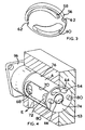
- the inlet chamber 40 is connected to a pressure inlet passage 54 which opens to an end face 53 of the valve cylinder 6 through an aperture in a control plate 56 ( Figures 2 and 3).
- the control plate 56 is in the form of a metal disc with two arcuate apertures 58 and 60, the aperture 58 being radially narrower than aperture 60 and both narrowing from one end to the other.
- the plate 56 also comprises two diametrically opposed notches 62.
- the plate 56 lies between an end face of the end portion 30 of the valve body 8 and the end face of the valve cylinder 6, and is positioned with respect to the valve body 8 and the valve cylinder 6 by a pin 57 ( Figure 7) secured in the valve cylinder 6 and which protrudes through one of the notches 62 and into a corresponding notch in the end portion 30 of the valve body 8.
- the pressure inlet passage 54 opens to an inlet aperture 64 in the circular end face 53 of the valve cylinder 6.
- the outlet chamber 42 is connected to a pressure outlet passage 66 through diametrically opposed openings 68 (only one of which is shown in Figure 4) in the valve cylinder 6, through opposed milled grooves 70 in the cylinder 6 and transverse passages 72 in the valve cylinder 6 which lead to the passage 66.
- the pressure outlet passage 66 opens to a central outlet aperture 74 in the end face 53 of the cylinder 6.
- the valve 2 is intended for use in a valve block which comprises a series of cylindrical bores (as shown at 76 in Figure 4).
- An end face of bore 76 is provided with a central opening, which when the valve is in position corresponds with the central aperture 74 and leads to the consumer, i.e. the mechanism to be supplied with compressed air, and with two, diametrically opposed, arcuate apertures, one of which leads to a supply of high pressure air and one to a supply of compressed air at a lower pressure.
- the end face of the bore 76 is also provided with two diametrically opposed sockets.
- valve When the valve is in position in the bore 76, pins 80 on the end face of the valve cylinder 6 are located in these sockets, and the valve can be positioned in one of two 180° opposed positions, one with the inlet aperture 64 matching with the arcuate aperture leading to high pressure air, and the other with the inlet aperture matching with that leading to low pressure air.
- the valve 2 is constructed to comprise means for adjusting the flow of air to exhaust from the exhaust chamber 44.
- An exhaust control sleeve 82 (see Figure 6) is positioned over an end portion of the valve body 8.
- the sleeve 82 comprises an end face 84 which is provided with a centrally positioned elongated aperture 86 and a cross recess 88 at 90° to the length of the aperture 86.
- a generally cylindrical portion 90 extends from the end face 84 and surrounds the end portion of the valve body 8. This cylindrical portion is provided with a slot 92 which extends part way around the circumference of the portion 90 from an enlarged aperture 94.
- the aperture 94 is the same size as the exhaust opening 52 in the valve cylinder 6, while the slot 92 extends about 270° from the aperture 94 and is progressively narrower along its length.
- valve cylinder 6 is attached to a fixing plate 96 by which the valve may be secured to the valve block 4.
- a knob 98 lies against the plate 96 and is connected to a stub shaft 100 which extends through the plate 96 to a cross bar 102 which lies in the cross recess 88.
- Pilot air to operate the valve i.e. to cause movement of the piston 10 against the spring 34 is provided through a passage (not shown) in the fixing plate 96 into a recess 104 ( Figure 6) bounded by the end face 84 and a rearward extension 106 of the cylindrical portion 90.
- the pilot air can pass through the aperture 86 from the recess 104 into a chamber 108 formed between the operating piston 14, the control sleeve 82 and the bore 29. Pilot air provided into the chamber 108 thus operates the valve piston 10 against the spring 34.
- control sleeve 82 is shown in position with the aperture 94 in the sleeve in position against the exhaust opening 52. This is the position in which a maximum flow of air to exhaust from the exhaust chamber 44 is obtained. It can be seen that by the use of the knob 98 the control sleeve 82 can be rotated to bring progressively narrower portions of the groove 92 opposite the exhaust opening 52, thus to restrict the rate of flow of air to exhaust.
- the valve body 8 is constrained from rotation when the knob 98 is rotated by the aforementioned pin 57 secured in the valve cylinder 6.
- FIG. 2 shows a second valve 2' embodying the invention which is similar to the valve 2 but is constructed to comprise means for adjusting the flow of air from the supply to the outlet passage.
- valve 2' embodying the invention which is similar to the valve 2 but is constructed to comprise means for adjusting the flow of air from the supply to the outlet passage.
- the valve 2' differs from the valve 2 primarily in that the exhaust control sleeve 82 is removed, and the valve body 8 is rotatable within the valve cylinder 6, i.e. the pin 57 (Fig. 7) has been removed and replaced by a shorter pin 157 (Fig. 8) which is fixed in the valve cylinder 6 and lies in the notch 62 in the plate 56 without extending into the valve body 8.
- valve 2' comprises a sleeve 114 which fits around the end portion 28 of the valve body 8.
- the sleeve 114 comprises four radially spaced lugs 115 which engage in corresponding notches in the valve body 8 so that rotation of the sleeve 114 will cause rotation of the valve body.
- the sleeve 114 corresponds generally to a portion of the control sleeve 82 and comprises an end face 184 which is provided with a centrally positioned elongated aperture 186 and a cross recess 188 at 90° to the aperture 186.
- a generally cylindrical portion 190 extends from the end face 184 and surrounds the end portion of the valve body 8.
- the knob 98 again is connected to the cross bar 102 which lies in the cross recess 188. Air can be supplied to operate the piston 14 in exactly the same way as in the valve 2.
- valve 2' rotation of the knob 98 causes rotation of the valve body 8 in the valve cylinder 6, with respect to the control plate 56.
- the effective size of the aperture in the plate 56 allowing for passage of air from the inlet passage 54 to the inlet chamber 40, can be adjusted, thus to modify the rate of flow of air to the chamber 40 by more or less of the aperture 58 being covered by the end face 30 of the valve body 8.
- the valves 2 and 2' are both normally closed.
- valve body 8 and valve piston 10 in the valves 2 and 2' is identical.
- the components of the valve piston 10 are of particularly simple and economic construction and are such that they may readily be assembled. Further they may also readily be assembled into a condition, as shown in Figure 5, where they provide a normally open valve construction.
- the two sealing heads 16, 22 are identical. As shown, the sealing heads are separate from the spacers 18 and 20, but if desired the sealing head 16 may be integral with the spacer 18 and the sealing head 22 integral with the spacer 20.
- the spacers 18 and 20 are so dimensioned as to pass freely through the apertures 36, 38 of the valve body 8.
- the valve body 8 comprises three longitudinal connecting straps which interconnect the end portion 30, the two wall portions 24, 26 and the end portion 28.
- a first one, 31, of these straps is located at the bottom of the valve body, viewing Figures 1 and 5.
- Second and third straps 33 extend slightly above the center line of the valve body, viewing Figures 1 and 5.
- the spacing of the upper two straps is such that, when the valve is assembled, the sealing heads and spacers, whether or not integral, can be passed through the gap between the straps and positioned as desired in the valve body (either in the configuration of Figure 1 or the configuration of Figure 2) with the spacers lying in the apertures 36, 38 in the walls 24, 26.
- the valve is then assembled by the piston rod 12 being pushed through the sealing heads and the spacers.
- the sealing heads and the spacers are welded together to each other and to the operating piston 14, preferably by ultrasonic welding.
- the sealing heads and spacers are preferably made from polyoxymethylene (Delrin T.M.) or from polysulphone.
- the piston rod 12 may be of metal or alternatively may also be of the same plastics material as the sealing heads; in the latter case the sealing heads may be welded together by both being welded to the piston rod.
Landscapes
- Engineering & Computer Science (AREA)
- General Engineering & Computer Science (AREA)
- Mechanical Engineering (AREA)
- Chemical & Material Sciences (AREA)
- Manufacturing & Machinery (AREA)
- Materials Engineering (AREA)
- Organic Chemistry (AREA)
- Fluid-Driven Valves (AREA)
- Multiple-Way Valves (AREA)
- Lift Valve (AREA)
- Mechanically-Actuated Valves (AREA)
- Taps Or Cocks (AREA)
Claims (10)
- Soupape pneumatique à cartouche comportant : un cylindre de soupape (6)
un corps de soupape (8) situé dans le cylindre de soupape (6),
un piston de soupape (10) monté pour se déplacer dans le corps de soupape (8) et comportant une tige de piston (12) qui supporte un piston d'actionnement (14) à une extrémité,
le corps de soupape comportant deux parois de séparation (24, 26) ayant chacune une ouverture axiale (36, 38), et
des première et seconde têtes d'étanchéité (16, 22) situées sur la tige de piston (12), adaptées à une course du piston de soupape (10) pour ouvrir et fermer les ouvertures (36, 38),
caractérisée en ce que :le corps de soupape (8) est en une seule pièce, et comporte une première partie d'extrémité (30) qui supporte une extrémité de la tige de piston (12) et une seconde partie d'extrémité (28) ayant un alésage qui supporte le piston (14),la première partie d'extrémité (30), les deux parois de séparation (24, 26) et la seconde partie d'extrémité (28) sont connectées mutuellement par des attaches longitudinales (31, 33) dans une relation où elles sont espacées axialement,les têtes d'étanchéité (16, 22) sont identiques, et chacune est adaptée pour venir en prise avec une des parois (24, 26) pour rendre étanches les ouvertures (36, 38), et chacune a une entretoise (18, 20) de diamètre réduit allongée axialement adjacente identique dimensionnée pour passer à travers les ouvertures (36, 38), etl'écartement des attaches (31, 33) est tel que lorsque la soupape est assemblée, les têtes d'étanchéité (16, 22) et les entretoises (18, 20) peuvent être passées entre les attaches (31, 32) et positionnées comme souhaité dans le corps de soupape (8), les entretoises se trouvant dans les ouvertures (36, 38) et la soupape enfin assemblée en faisant passer la tige de piston (12) à travers les têtes d'étanchéité (16, 22) et les entretoises (18, 20). - Soupape selon la revendication 1, dans laquelle
les parois de séparation (24, 26) séparent le cylindre de soupape (6) en trois chambres, une chambre d'entrée (40) qui peut être reliée à une alimentation en air comprimé, une chambre de sortie (42) qui peut être reliée à un consommateur d'air comprimé, et une chambre d'échappement (44) qui peut être reliée à l'échappement,
le cylindre de soupape (6) comporte une face d'extrémité (53) ayant un passage d'entrée (54) adapté pour être relié à l'alimentation, et un passage de sortie (66) adapté pour être relié au consommateur, et
la soupape comporte des moyens d'ajustement du de l'écoulement d'air allant du consommateur jusqu'à l'échappement, ou de l'alimentation jusqu'au consommateur,
lesquels moyens comportent un bouton de commande (98) monté axialement par rapport au corps de soupape, par rotation duquel un élément (82, 8) est mis en rotation pour ajuster l'écoulement d'air à évacuer allant jusqu'à l'échappement ou le passage d'air allant de l'alimentation jusqu'au consommateur. - Soupape selon la revendication 2, dans laquelle
les moyens d'ajustement de l'écoulement d'air allant de l'alimentation jusqu'au consommateur comportent le bouton de commande (98) qui est monté axialement par rapport au corps de soupape (8), et qui est relié au corps de soupape pour permettre au corps de soupape (8) d'être mis en rotation par rapport au cylindre de soupape (6), et une plaque de commande (56) comportant une ouverture de largueur variable interposée entre le passage d'entrée (54) et la chambre d'entrée (40),
de sorte qu'une rotation du bouton de commande (98) ajuste l'écoulement d'air allant de l'alimentation jusqu'à la chambre d'entrée en modifiant l'ouverture effective dans la plaque de commande. - Soupape selon la revendication 2, dans laquelle
les moyens d'ajustement de l'écoulement d'air allant du consommateur jusqu'à l'échappement comportent le bouton de commande (98) qui est monté axialement par rapport au corps de soupape (8), et un manchon de commande d'échappement (82) monté pour rotation dans le cylindre de soupape (6) et est connecté au bouton de commande (98), lequel manchon (82) comporte une fente circonférentielle qui conduit de la chambre d'échappement à un passage d'échappement, la rotation du manchon (82) ajustant la longueur de la fente à travers laquelle de l'air peut s'écouler, et donc l'écoulement d'air allant de la chambre jusqu'à l'échappement. - Soupape selon la revendication 3, dans laquelle la plaque de commande (56) est fixe par rapport au cylindre de soupape (6) et se trouve entre le cylindre de soupape (6) et le corps de soupape (8), et une rotation du bouton de commande (98) provoque une rotation du corps de soupape par rapport à la plaque de commande, pour obtenir ainsi plus ou moins de recouvrement de l'ouverture située dans la plaque de commande.
- Soupape selon l'une quelconque des revendications 2, 3 et 4, dans laquelle un passage parmi le passage d'entrée et le passage de sortie est au centre de la face d'extrémité du cylindre de soupape (6).
- Soupape selon la revendication 1, dans laquelle les têtes d'étanchéité (16, 22) sont toutes deux positionnées sur la tige de piston (12) entre les parois de séparation (24, 26).
- Soupape selon la revendication 1, dans laquelle les têtes d'étanchéité (16, 22) sont positionnées sur la tige de piston (12), l'une entre une première paroi de séparation (24) et le piston d'actionnement (14), et l'autre entre l'autre paroi de séparation (26) et la première partie d'extrémité (30) du corps de soupape (8).
- Soupape selon l'une quelconque des revendications 7 et 8, dans laquelle chaque tête d'étanchéité (16, 22) est en un seul bloc avec son entretoise associée (18, 20).
- Soupape selon l'une quelconque des revendications 7, 8 et 9, dans laquelle les têtes d'étanchéité (16, 22) et les entretoises (18, 20) sont en matières plastiques.
Applications Claiming Priority (2)
| Application Number | Priority Date | Filing Date | Title |
|---|---|---|---|
| GBGB9809034.3A GB9809034D0 (en) | 1998-04-29 | 1998-04-29 | Pneumatic cartridge valve |
| GB9809034 | 1998-04-29 |
Publications (3)
| Publication Number | Publication Date |
|---|---|
| EP0953794A2 EP0953794A2 (fr) | 1999-11-03 |
| EP0953794A3 EP0953794A3 (fr) | 2001-04-18 |
| EP0953794B1 true EP0953794B1 (fr) | 2004-08-18 |
Family
ID=10831101
Family Applications (1)
| Application Number | Title | Priority Date | Filing Date |
|---|---|---|---|
| EP99303247A Expired - Lifetime EP0953794B1 (fr) | 1998-04-29 | 1999-04-27 | Soupape à cartouche pneumatique |
Country Status (6)
| Country | Link |
|---|---|
| US (1) | US6123096A (fr) |
| EP (1) | EP0953794B1 (fr) |
| JP (2) | JP4342633B2 (fr) |
| CZ (1) | CZ296452B6 (fr) |
| DE (1) | DE69919438T2 (fr) |
| GB (1) | GB9809034D0 (fr) |
Cited By (1)
| Publication number | Priority date | Publication date | Assignee | Title |
|---|---|---|---|---|
| US9016305B2 (en) | 2011-05-05 | 2015-04-28 | Norgren Gt Development Corporation | Configurable actuation-orientation valve |
Families Citing this family (10)
| Publication number | Priority date | Publication date | Assignee | Title |
|---|---|---|---|---|
| DE10203886B4 (de) * | 2002-01-31 | 2005-04-14 | Dbt Automation Gmbh | Vorsteuerventil |
| EP1367306A1 (fr) * | 2002-05-31 | 2003-12-03 | Grundfos a/s | Cartouche de soupape |
| US6871668B2 (en) * | 2003-01-13 | 2005-03-29 | Delphi Technologies Inc. | Variable force actuator with a double needle poppet assembly |
| US20090205372A1 (en) * | 2005-07-13 | 2009-08-20 | Toyko Electron Limited | Method and device for forming hole in glass substrate |
| US20070092385A1 (en) * | 2005-10-20 | 2007-04-26 | Petrie Pe Greg A | Pump and valve actuator system and method |
| US8549884B2 (en) * | 2007-11-29 | 2013-10-08 | Owens-Brockway Glass Container Inc. | Bottom plate lift mechanism for a glassware forming machine |
| CN202884121U (zh) * | 2012-08-24 | 2013-04-17 | 成霖企业股份有限公司 | 转换阀 |
| US9732876B2 (en) | 2013-11-05 | 2017-08-15 | Edco Usa | Retarder control valve assembly and system for rail cars |
| US10753420B2 (en) * | 2018-04-16 | 2020-08-25 | Beijingwest Industries Co., Ltd. | Rotating three way valve for switchable air springs |
| DE102018114849A1 (de) * | 2018-06-20 | 2019-12-24 | Johnson Electric Germany GmbH & Co. KG | Dichtsystem für umschaltbare Wasserventile |
Family Cites Families (7)
| Publication number | Priority date | Publication date | Assignee | Title |
|---|---|---|---|---|
| US3779280A (en) * | 1972-08-17 | 1973-12-18 | Whitlock Inc | Control valve for contaminant-laden gases |
| US4034899A (en) * | 1975-03-20 | 1977-07-12 | Philip Meshberg | Valve construction |
| SE403395B (sv) * | 1975-09-19 | 1978-08-14 | Atlas Copco Ab | Uariabel pneumatisk strypventil |
| US4100937A (en) * | 1976-08-16 | 1978-07-18 | Owens-Illinois, Inc. | Valve block |
| JPS6432973U (fr) * | 1987-08-21 | 1989-03-01 | ||
| US5320130A (en) * | 1993-04-15 | 1994-06-14 | Emhart Glass Machinery Investments Inc. | Valve block assembly for I.S. machine |
| DE69411979T2 (de) * | 1993-04-15 | 1998-12-10 | Emhart Glass Machinery Investments Inc., Wilmington, Del. | Ventilblock für eine I.S.-Maschine |
-
1998
- 1998-04-29 GB GBGB9809034.3A patent/GB9809034D0/en not_active Ceased
-
1999
- 1999-04-14 CZ CZ0131499A patent/CZ296452B6/cs not_active IP Right Cessation
- 1999-04-27 JP JP11972399A patent/JP4342633B2/ja not_active Expired - Fee Related
- 1999-04-27 EP EP99303247A patent/EP0953794B1/fr not_active Expired - Lifetime
- 1999-04-27 DE DE1999619438 patent/DE69919438T2/de not_active Expired - Lifetime
- 1999-04-28 US US09/301,663 patent/US6123096A/en not_active Expired - Lifetime
-
2008
- 2008-10-29 JP JP2008277764A patent/JP2009058131A/ja active Pending
Cited By (1)
| Publication number | Priority date | Publication date | Assignee | Title |
|---|---|---|---|---|
| US9016305B2 (en) | 2011-05-05 | 2015-04-28 | Norgren Gt Development Corporation | Configurable actuation-orientation valve |
Also Published As
| Publication number | Publication date |
|---|---|
| CZ9901314A3 (cs) | 2001-02-14 |
| CZ296452B6 (cs) | 2006-03-15 |
| JP4342633B2 (ja) | 2009-10-14 |
| EP0953794A2 (fr) | 1999-11-03 |
| JP2009058131A (ja) | 2009-03-19 |
| US6123096A (en) | 2000-09-26 |
| JP2000035142A (ja) | 2000-02-02 |
| GB9809034D0 (en) | 1998-06-24 |
| DE69919438T2 (de) | 2005-01-13 |
| EP0953794A3 (fr) | 2001-04-18 |
| DE69919438D1 (de) | 2004-09-23 |
Similar Documents
| Publication | Publication Date | Title |
|---|---|---|
| EP0953794B1 (fr) | Soupape à cartouche pneumatique | |
| US2321336A (en) | Valve | |
| US4924903A (en) | `Breech-block` tap for the supply of cold or hot water with ceramic sealing plates | |
| KR20060007373A (ko) | 조정 가능한 정지 수단이 구비된 밸브 | |
| NO344097B1 (no) | Reguleringsventil og strømningsjusteringsanordning | |
| JPH04339796A (ja) | 流体の流れの制御 | |
| US5375994A (en) | Piston driven pin closure nozzle assembly | |
| US6843266B2 (en) | Regulator with erosion resistant seal assemblies | |
| CA2452809C (fr) | Robinet a membrane comprenant un dispositif de fermeture reglable | |
| JP3140786B2 (ja) | 混合バルブ用ボールバルブカートリッジ | |
| US4882977A (en) | Rotary actuator | |
| EP0756090B1 (fr) | Vanne de commutation pilotée | |
| US6131611A (en) | Cartridge or mechanism for a sequential mixing valve | |
| EP1566552B1 (fr) | Verin a pression fluidique | |
| EP0167497B1 (fr) | Vérin pneumatique semi-rotatif à simple effet | |
| CA1258417A (fr) | Robinet regulateur de debit | |
| US6065487A (en) | Valve with different configurations for different uses | |
| US4348160A (en) | Metering syringe | |
| JP2001512557A (ja) | 改良されたバルブ構造 | |
| US6481454B2 (en) | Regulator with segmented body | |
| EP0137938B1 (fr) | Dispositif pneumatique de commande de position | |
| JP4262325B2 (ja) | バルブブロック | |
| EP1134469B1 (fr) | Distributeur à vanne avec fixation de chapeaux | |
| US5427142A (en) | Valve device for use in electro-hydraulic control systems of mining installations | |
| EP0122247A1 (fr) | Valve de commande |
Legal Events
| Date | Code | Title | Description |
|---|---|---|---|
| PUAI | Public reference made under article 153(3) epc to a published international application that has entered the european phase |
Free format text: ORIGINAL CODE: 0009012 |
|
| AK | Designated contracting states |
Kind code of ref document: A2 Designated state(s): DE FR GB IT |
|
| AX | Request for extension of the european patent |
Free format text: AL;LT;LV;MK;RO;SI |
|
| RIN1 | Information on inventor provided before grant (corrected) |
Inventor name: KAMMONEN, JARMO |
|
| PUAL | Search report despatched |
Free format text: ORIGINAL CODE: 0009013 |
|
| AK | Designated contracting states |
Kind code of ref document: A3 Designated state(s): AT BE CH CY DE DK ES FI FR GB GR IE IT LI LU MC NL PT SE |
|
| AX | Request for extension of the european patent |
Free format text: AL;LT;LV;MK;RO;SI |
|
| RIC1 | Information provided on ipc code assigned before grant |
Free format text: 7F 16K 27/02 A, 7C 03B 9/40 B |
|
| 17P | Request for examination filed |
Effective date: 20010803 |
|
| AKX | Designation fees paid |
Free format text: DE ES FR GB |
|
| RBV | Designated contracting states (corrected) |
Designated state(s): DE FR GB IT |
|
| RAP1 | Party data changed (applicant data changed or rights of an application transferred) |
Owner name: EMHART GLASS S.A. |
|
| 17Q | First examination report despatched |
Effective date: 20030902 |
|
| GRAP | Despatch of communication of intention to grant a patent |
Free format text: ORIGINAL CODE: EPIDOSNIGR1 |
|
| GRAS | Grant fee paid |
Free format text: ORIGINAL CODE: EPIDOSNIGR3 |
|
| GRAA | (expected) grant |
Free format text: ORIGINAL CODE: 0009210 |
|
| AK | Designated contracting states |
Kind code of ref document: B1 Designated state(s): DE FR GB IT |
|
| REG | Reference to a national code |
Ref country code: GB Ref legal event code: FG4D |
|
| REF | Corresponds to: |
Ref document number: 69919438 Country of ref document: DE Date of ref document: 20040923 Kind code of ref document: P |
|
| ET | Fr: translation filed | ||
| PLBE | No opposition filed within time limit |
Free format text: ORIGINAL CODE: 0009261 |
|
| STAA | Information on the status of an ep patent application or granted ep patent |
Free format text: STATUS: NO OPPOSITION FILED WITHIN TIME LIMIT |
|
| 26N | No opposition filed |
Effective date: 20050519 |
|
| PGFP | Annual fee paid to national office [announced via postgrant information from national office to epo] |
Ref country code: FR Payment date: 20110504 Year of fee payment: 13 Ref country code: DE Payment date: 20110427 Year of fee payment: 13 |
|
| PGFP | Annual fee paid to national office [announced via postgrant information from national office to epo] |
Ref country code: GB Payment date: 20110426 Year of fee payment: 13 |
|
| PGFP | Annual fee paid to national office [announced via postgrant information from national office to epo] |
Ref country code: IT Payment date: 20110429 Year of fee payment: 13 |
|
| GBPC | Gb: european patent ceased through non-payment of renewal fee |
Effective date: 20120427 |
|
| REG | Reference to a national code |
Ref country code: FR Ref legal event code: ST Effective date: 20121228 |
|
| PG25 | Lapsed in a contracting state [announced via postgrant information from national office to epo] |
Ref country code: GB Free format text: LAPSE BECAUSE OF NON-PAYMENT OF DUE FEES Effective date: 20120427 |
|
| REG | Reference to a national code |
Ref country code: DE Ref legal event code: R119 Ref document number: 69919438 Country of ref document: DE Effective date: 20121101 |
|
| PG25 | Lapsed in a contracting state [announced via postgrant information from national office to epo] |
Ref country code: FR Free format text: LAPSE BECAUSE OF NON-PAYMENT OF DUE FEES Effective date: 20120430 Ref country code: IT Free format text: LAPSE BECAUSE OF NON-PAYMENT OF DUE FEES Effective date: 20120427 |
|
| PG25 | Lapsed in a contracting state [announced via postgrant information from national office to epo] |
Ref country code: DE Free format text: LAPSE BECAUSE OF NON-PAYMENT OF DUE FEES Effective date: 20121101 |