EP0953802A2 - Dispositif d' éclairage pour lampe fluorescente sans électrodes - Google Patents
Dispositif d' éclairage pour lampe fluorescente sans électrodes Download PDFInfo
- Publication number
- EP0953802A2 EP0953802A2 EP99108422A EP99108422A EP0953802A2 EP 0953802 A2 EP0953802 A2 EP 0953802A2 EP 99108422 A EP99108422 A EP 99108422A EP 99108422 A EP99108422 A EP 99108422A EP 0953802 A2 EP0953802 A2 EP 0953802A2
- Authority
- EP
- European Patent Office
- Prior art keywords
- reflector
- fluorescent lamp
- lamp
- light
- arrangement
- Prior art date
- Legal status (The legal status is an assumption and is not a legal conclusion. Google has not performed a legal analysis and makes no representation as to the accuracy of the status listed.)
- Ceased
Links
Images

Classifications
-
- F—MECHANICAL ENGINEERING; LIGHTING; HEATING; WEAPONS; BLASTING
- F21—LIGHTING
- F21V—FUNCTIONAL FEATURES OR DETAILS OF LIGHTING DEVICES OR SYSTEMS THEREOF; STRUCTURAL COMBINATIONS OF LIGHTING DEVICES WITH OTHER ARTICLES, NOT OTHERWISE PROVIDED FOR
- F21V7/00—Reflectors for light sources
- F21V7/0058—Reflectors for light sources adapted to cooperate with light sources of shapes different from point-like or linear, e.g. circular light sources
-
- F—MECHANICAL ENGINEERING; LIGHTING; HEATING; WEAPONS; BLASTING
- F21—LIGHTING
- F21V—FUNCTIONAL FEATURES OR DETAILS OF LIGHTING DEVICES OR SYSTEMS THEREOF; STRUCTURAL COMBINATIONS OF LIGHTING DEVICES WITH OTHER ARTICLES, NOT OTHERWISE PROVIDED FOR
- F21V7/00—Reflectors for light sources
- F21V7/0008—Reflectors for light sources providing for indirect lighting
- F21V7/0016—Reflectors for light sources providing for indirect lighting on lighting devices that also provide for direct lighting, e.g. by means of independent light sources, by splitting of the light beam, by switching between both lighting modes
Definitions
- the invention relates to a lamp with an electrodeless fluorescent lamp as a light source according to the preamble of claim 1.
- DE-A1-26 01 666 describes an example of a way of solving this problem.
- An electrodeless fluorescent lamp with a is known from this document self-contained filament in the form of a toroid.
- a gaseous medium is trapped by a high-frequency magnetic field is ionized in order on the inside of the filament Fluorescent layer to stimulate light generation.
- the magnetic field is generated by a magnetic coil generated, which is placed around a segment of the filament.
- the electrodeless fluorescent lamp has long been known per se. Despite the undeniable advantage of one over conventional, over Electrode-excited fluorescent lamps have a significantly longer lifespan not yet established on the market.
- this fluorescent lamp is also based on the above-mentioned principle of using electromagnetic induction to transmit the necessary electrical operating energy into the luminous element which is closed on all sides.
- the filament consists of two elongated tubular legs which are spaced parallel to one another and connected to one another to form a closed arrangement.
- a magnetic coil is placed around the luminous element, via which the energy required for operation is induced in the luminous element.
- the lamp manufacturer specifies the special advantages of this lamp type as being a long lifespan of up to five times that of a conventional fluorescent lamp, a high luminous flux with an unprecedented luminous efficacy and a flat design. This makes this type of lamp particularly suitable for all those applications in which changing the lamp is complex and expensive.
- the selected lamp geometry is the use of the lamp in allows relatively flat lights, so there is for the light manufacturer who Want to use the light source, but the problem, but a luminaire with a reflector geometry to create the best possible match to the lamp geometry a well-coordinated for a required light emission characteristic of the luminaire Allows light control with high efficiency.
- an electrodeless fluorescent lamp of the type mentioned this is made more difficult by the fact that it is by no means as punctiform, not even like a conventional fluorescent lamp as can be seen to extend essentially along an axis in the form of a rod.
- the discussed The lamp type is rather a flat structure at best, in which the Diameter of the filament is by no means negligible, since it is considerably larger is the average of conventional rod-shaped fluorescent lamps.
- the invention is therefore based on the object of a lamp of the type mentioned kind of creating with a reflector geometry that despite being at least as areal evaluating lamp design with the simplest possible means a favorable light control allowed to achieve, the prerequisite for good lighting efficiency is.
- a lamp in particular an interior lamp with an electrodeless fluorescent lamp as a light source, one in itself closed filament with at least two tubular sections connected to each other, preferably a luminous element in the form of two mutually parallel, one below the other connected tubular leg, and associated with this light source light-directing reflector means for achieving a predetermined light distribution characteristic the lamp, which is characterized in that the reflector means as the first or second, essentially one of the two sections or legs of the Fluorescent lamp associated reflector arrangements are formed.
- Said sections do not necessarily have to be structurally different from the rest of the lamp and can in particular be partial sections of an annular lamp.
- the invention can in particular provide that at least one of the two reflector arrangements is set up for indirect lighting.
- a reflector arrangement for emitting light upwards e.g. against a ceiling, or that one, both, or, in the case of more than two Reflector arrangements, several or all reflector arrangements secondary beam arrangements are.
- one of the reflector arrangements has a curved one Primary reflector forms or has and that this primary reflector as a further light-directing A secondary reflector is assigned to the reflector means.
- one or more reflector arrangements one Have primary reflector and a secondary reflector, which of the associated Lamp section directly incident on and reflected by the primary reflector substantially completely incident on the secondary reflector, such that that of the associated one Lamp section emitted light at least predominantly, preferably essentially is completely emitted via the secondary reflector.
- the lamp as a whole is designed as a secondary lamp and all reflector arrangements are a primary reflector and a secondary reflector have, the primary reflector directly incident light from the associated Lamp section reflected to the secondary reflector and that of the corresponding Lamp section emitted light at least predominantly, preferably essentially completely, via which the associated secondary reflector is emitted.
- the invention can provide that the first and second reflector arrangement, respectively at least one arched in cross-section and in the longitudinal direction perpendicular thereto the respective associated leg of the fluorescent lamp is assigned a reflector element parallel to the axis having.
- the angular range in which the first reflector arrangement Light emits is different from the corresponding angular range in which the second Reflector arrangement emits light, and preferably not overlapped with it.
- the reflector elements belonging to the different reflector arrangements do not have to must be structurally separate. For example, you can have adjacent sections of a single component. It can also be provided that the front of a component an element of the first reflector arrangement and the rear an element of the second reflector arrangement is.
- the reflecting surfaces of the reflector elements the first and second reflector arrangements are oriented facing away from each other.
- the arrangement of the reflector elements of different reflector arrangements or the The shape of the reflector elements within a reflector arrangement can preferably be corresponding a certain symmetry.
- the first or second reflector arrangements are each composed of reflector elements, which refer to a luminaire level, the one plane of symmetry for the two legs or sections of the fluorescent lamp forms, arranged mirror-symmetrically to the elements of the other arrangement are.
- the reflector element or elements of the first and / or second Reflector arrangement with respect to a plane which is a plane of symmetry of the tubular Sections or, according to a preferred embodiment, the two legs, the Fluorescent lamp forms, are arranged in mirror image symmetry and / or are formed.
- the reflector element or elements of the first reflector arrangement with respect to an axis with respect to which the legs of the lamp are arranged symmetrically are symmetrical to the reflector element or elements of the second reflector arrangement are arranged.
- the one or more reflector elements of the first and the second reflector arrangement can also be arranged so that the reflector element or elements of the first reflector arrangement a rotation about an axis with respect to which the legs of the lamp are arranged symmetrically are in the position of the reflector element or elements of the second reflector arrangement can be transferred.
- the reflector elements of the first reflector arrangement do not necessarily have to be symmetrical Be images of the reflector elements of the second reflector arrangement.
- the reflector elements of the first and second reflector arrangement the one another correspond to the symmetry, formed with a different cross-sectional profile which correspond to the symmetry (e.g. axis symmetry, plane symmetry) at least essentially in the same half-space (e.g. with plane symmetry) or at least emit light essentially in different half-spaces (e.g. with axis symmetry).
- reflector elements of the first or second Reflector arrangements are arranged adjacent to each other in the area of the luminaire center plane are, in particular a reflector element of the first reflector arrangement in the reverse Direction like an adjacent reflector element of the second reflector arrangement can be arched.
- tubular sections or the legs can be perpendicular or transverse to the main emission direction the luminaire and usually parallel to a plane through the light exit opening lie.
- the primary reflector can be curved like a swinging wing and one on the connecting line have the apex of the center of the two legs of the fluorescent lamp.
- the two legs of the fluorescent lamp in the direction of Main radiation of the lamp considered, one above the other, that a Vogeischwingen-like reflector arrangement as the primary reflector above Leg of the fluorescent lamp is assigned such that one emitted by this Partial luminous flux of the fluorescent lamp in the upper half-space towards the secondary reflector is emitted directly or via the primary reflector, which in turn has this partial luminous flux reflected in the lower half-space and that the other the second leg of the Fluorescent lamp associated reflector arrangement as a partially surrounding this leg and the further partial luminous flux of the fluorescent lamp radiated by this directly is formed in the lower half-space emitting reflector element.
- Such a lamp can be used as an outdoor lamp with an asymmetrical light emission be configured, wherein the secondary reflector and the electrodeless fluorescent lamp as well the associated first and second reflector arrangements spatially adjacent to each other are arranged together at the end of a lamp pole.
- the fluorescent lamp and the associated first and second reflector assemblies arranged together in a housing attached to the side of the lamp pole are and the secondary reflector also like an umbrella on the lamp mast is set, the housing and / or the secondary reflector in the form or according to Art a pole-mounted luminaire can be designed.
- the secondary reflector can have a grid-like structure local curvatures and thereby be stiffened self-supporting.
- annular fluorescent lamp can be divided into two, three, four or more sections become.
- the solution according to the invention is based on these conventional assumptions, the one to be used Light source as an almost punctiform or as an approximately linear one To understand the light source. Instead, in this case, and thus in contrast to the usual approaches for the design of the reflector geometry of a If the light source is no longer considered as one unit.
- the reflector geometry is used to enable optimized luminaire designs individually according to the invention, based on each of the two legs of the filament of the electrodeless fluorescent lamp selected. With that the due to the design of the electrodeless fluorescent lamp a disadvantage large area expansion converted into an advantage.
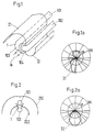
- a lamp is shown schematically in a three-dimensional partial view, in which an electrodeless fluorescent lamp 1 is used as the light source.
- the electrodeless fluorescent lamp has two parallel tubular, arranged at a predetermined distance from each other Legs 101 and 102, which are at their two ends with each other via a pipe bend 103 are connected to a closed filament.
- This type of lamp becomes the energy required for operation by means of electromagnetic induction transported without electrodes into the interior of the fluorescent lamp 1.
- These are in the area of the pipe bends 103 are provided coaxially arranged electromagnets 104, which as schematically indicated by arrows, operating current ib is supplied.
- electromagnets 104 which as schematically indicated by arrows, operating current ib is supplied.
- the electrodeless fluorescent lamp 1 illustrated in FIG. 1 and explained above is a relative to the longitudinal axis of the legs 101 and 102 respectively flat structure; due to its longitudinal and transverse dimensions, however, it represents one relatively large-area luminous body, which for the lighting technician when designing a optimally adapted lamp is not easily controllable.
- the non-negligible longitudinal and transverse dimensions of the filament which the design of in terms of a light distribution characteristic a lamp means necessary to direct the electrodeless fluorescent lamp 1 make light emitted difficult. This is illustrated by an example.
- this problem is now solved in that for this electrodeless fluorescent lamp 1 light-directing means are provided, which consist of two reflector arrangements 21 or 22 are composed. Each of these reflector arrangements 21, 22 is preferred each on one of the two legs 101 and 102 of the electrodeless fluorescent lamp 1 related.
- first reflector arrangement 21 approximately involute around one leg 101 of the electrodeless Fluorescent lamp 1 placed.
- This first reflector arrangement 21 reflects that from the Leg 101 of the electrodeless fluorescent lamp 1 preferably emits light narrow beam in the lower half-space.
- a second, the other leg 102 of the electrodeless Fluorescent lamp 1 associated reflector assembly 22 is in profile with respect on this leg 102 and this from below, for example, approximated parabolic or partial ellipse.
- This second reflector arrangement 22 thus reflects that from the second leg 102 of the electrodeless fluorescent lamp radiated partial luminous flux in the upper half-space.
- the light distribution characteristic is that of Figure 1 Luminaire for an electrodeless fluorescent lamp 1 in the form of a diagram in polar coordinates shown.
- a curve branch directed into the lower half space refers the luminous intensity distribution curve 31 to the partial luminous flux of the luminaire, which the first reflector arrangement 21 is relatively strongly bundled in the lower half space becomes.
- the one emitted by the other leg 102 of the electrodeless fluorescent lamp 1 and partial luminous flux partially reflected by the second reflector arrangement 22 is in the other, upward branch of the luminous intensity distribution curve Play 31 of Figure 1a.
- the schematically shown in Figure 1 The shape of the luminaire is therefore functional as a direct / indirect luminaire, for example as a wall Ceiling lamp could be used indoors.
- FIG. 2 shows another possible embodiment of the light-directing means for one Luminaire with electrodeless fluorescent lamp - simplified only in cross section - shown.
- the two legs 101 and 102 are the electrodeless Fluorescent lamp 1 arranged one above the other.
- a first reflector arrangement 212 is shaped like a bird's wing in profile, the first leg 101 assigned to the electrodeless fluorescent lamp 1.
- With an approximately similar profile is a second reflector assembly 222 within the first around the second leg 102 of the electrodeless fluorescent lamp and has two reflective surfaces on.
- the light-directing means in the form of the reflector arrangements 212 or 222 the lamp emits that from the electrodeless fluorescent lamp 1 emitted light only in the lower half space.
- the electrodeless fluorescent lamp 1 with its two legs 101 and 102 lying horizontally, in other words mirror-symmetrical to one Luminaire center plane of the lamp arranged.
- the light-directing ones exist Means the lamp from a substantially above the electrodeless Fluorescent lamp 1 arranged main reflector and one of the electrodeless Fluorescent lamp 1 from below partially surrounding primary reflector. But is also here the selected assignment of the light-directing means to one of the two legs Given 101 and 102 of the electrodeless fluorescent lamp 1, if one Reflector arrangements 213 and 223 each on one side of the light center plane lying reflector elements considered together.
- FIG. 3a shows a corresponding luminous intensity distribution curve 33 that shown in FIG. 3 Luminaire design shown.
- this luminous intensity distribution curve 33 is a mirror image of the light center plane symmetrical and has a pronounced with a defined glare limitation Maximum in this light center level.
- FIG. 4 schematically shows an embodiment for a lamp with an electrodeless one Fluorescent lamp 1 shown, with which an indirectly radiating floor lamp is to be realized.
- the electrodeless fluorescent lamp 1 with its two legs 101 and 102 arranged horizontally.
- the one leg 101 of the electrodeless fluorescent lamp 1 assigned reflector arrangement 214 is relatively strongly curved. Of the Partial luminous flux of the luminaire emitted via them thus essentially forms one broad-spectrum portion radiated into the upper half-space.
- the second leg 102 is the reflector arrangement 224 assigned to the electrodeless fluorescent lamp 1 probably also initially arched relatively strongly in the vicinity of this leg but then outwards with decreasing curvature into a more or less flat Tail over.
- the second reflector arrangement 224 the of their reflected partial luminous flux, strongly asymmetrically directed, emitted into the upper half-space.
- a light distribution curve 34 shown in FIG. 4a in the polar diagram for this This reflects the shape of the luminaire immediately. Seen overall, the result is one-sided Luminous intensity distribution directed into the upper half space.
- FIG. 5 shows a possibility of using a lamp Electrodeless fluorescent lamp 1 to a corner lamp for wall and ceiling lighting to design.
- the two legs 101, 102 are the electrodeless ones Fluorescent lamp 1 aligned horizontally.
- the two each have one of the legs 101, 102 of the electrode-less fluorescent lamp 1 assigned reflector arrangements 215 and 225 are oriented facing away from each other and include the assigned leg of the electrodeless fluorescent lamp such that the of the first Reflector arrangement 215 emitted partial luminous flux bundled in the club lower half-space is emitted directed during that of the second reflector arrangement 225 partial luminous flux emitted at a relatively flat angle and also is directed relatively bundled into the upper half space.
- Luminous intensity distribution curve 35 shows these two distinct curve branches. Becomes the correspondingly designed luminaire is arranged close to the wall at ceiling height, so lights up the nearby wall surface from above and at the same time shines with a pronounced Ceiling lighting far into the room.
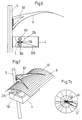
- FIG 6 in contrast to those described above, is essentially for the Indoors certain luminaire designs, one in a schematic side view Possibility of designing an outdoor lamp shown. It refers to a pole-top luminaire in which the electrodeless fluorescent lamp 1 with its two Legs 101 and 102 are arranged one above the other in a housing 4. Also in this embodiment, the one leg, in this case lying on top 101 the electrodeless fluorescent lamp 1 has a first reflector arrangement 216 and the other, lower leg 102 of the electrodeless fluorescent lamp 1 a second Associated reflector assembly 226.
- the first reflector arrangement 216 is off put together two curved reflector elements, their common apex on the connecting line of the two axis centers of the two legs 101 or 102 lies.
- This first reflector arrangement 216 comprises one leg 101 of the Electrodeless fluorescent lamp 1 from below and is open upwards.
- the second Reflector arrangement 226 is facing away from the first reflector arrangement 216 other leg 102 of the electrodeless fluorescent lamp arranged around and after opened below. Obviously it is asymmetrical, relative in the part near the lamp strongly arched and in the area to the right of the associated leg 102 in the essentially flat, this area facing downward at a flat angle is.
- the two are described Reflector assemblies 216 and 226 in that formed as a flat box Housing 4 arranged, which in turn laterally on a lamp pole 5 near the mast end is attached.
- an umbrella-shaped secondary reflector 6 is provided, cantilevered on the side of the housing 4 and above it at the end of the Luminaire mast is set.
- FIG. 7 is a three-dimensional view from above of the above with reference to Figure 6 described extension light shown again.
- This illustration shows that the secondary reflector 6, arching like a screen over the housing 4 is fixed by means of fastening angles 62 at the end of the lamp mast 5.
- This one Luminaire designed for outdoor use and therefore also corresponding wind loads is exposed, the reflector material 61 of the secondary reflector 6 at this constructive design in itself be stiffened accordingly.
- this material preferably has a honeycomb structure, consisting of a multitude of small local bumps.
- Such deformations of reflector materials are common in lighting technology, so that there is no need for further explanations here.
- the one leg 101 of the electrodeless Fluorescent lamp 1 associated first reflector assembly 216 causes that of this limb 101 of the electrodeless fluorescent lamp 1 emitted partial luminous flux relatively tightly bundled in the upper half-space towards the secondary reflector 6 is emitted. Because of the outward facing away from the mast approach Curvature of the secondary reflector 6 and the spatially closely adjacent arrangement the electrodeless fluorescent lamp 1 results in that of the associated leg 101 emitted by the electrodeless fluorescent lamp 1 and by the first reflector arrangement 216 bundled partial luminous flux at the secondary reflector 6 essentially of the lamp mast 5 is diverted away to the outside.
- a light intensity distribution curve 37 is in a further polar diagram this is emitted via the first reflector arrangement 216 and via the secondary reflector 6 redirected partial luminous flux of the outdoor light shown. It becomes clear the relatively flat achieved due to the flat design of the secondary reflector 6 Beam angle, which when the emitted partial luminous flux is closely bundled into one lobe-shaped luminous intensity distribution curve 37 leads.
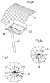
- the post-top luminaire from FIG. 6 is in one three-dimensional representation in a view from below.
- the secondary reflector 6 explained in detail is here in particular the most Lamp post 5 fixed housing 4 can now be seen from below.
- the second leg 102 of the electrodeless fluorescent lamp 1 in connection with the this associated second reflector arrangement 226 clearly.
- the one already described Arrangement results in interaction with the directly emitted light a partial luminous flux, which essentially faces away from the lamp mast 5 and after radiated outside in the lower half-space.
- Luminous intensity distribution curve 38 illustrates this partial luminous flux.
Landscapes
- Engineering & Computer Science (AREA)
- General Engineering & Computer Science (AREA)
- Non-Portable Lighting Devices Or Systems Thereof (AREA)
Applications Claiming Priority (2)
| Application Number | Priority Date | Filing Date | Title |
|---|---|---|---|
| DE1998119221 DE19819221A1 (de) | 1998-04-29 | 1998-04-29 | Leuchte für eine elektrodenlose Leuchtstofflampe |
| DE19819221 | 1998-04-29 |
Publications (2)
| Publication Number | Publication Date |
|---|---|
| EP0953802A2 true EP0953802A2 (fr) | 1999-11-03 |
| EP0953802A3 EP0953802A3 (fr) | 2001-10-31 |
Family
ID=7866216
Family Applications (1)
| Application Number | Title | Priority Date | Filing Date |
|---|---|---|---|
| EP99108422A Ceased EP0953802A3 (fr) | 1998-04-29 | 1999-04-29 | Dispositif d' éclairage pour lampe fluorescente sans électrodes |
Country Status (2)
| Country | Link |
|---|---|
| EP (1) | EP0953802A3 (fr) |
| DE (1) | DE19819221A1 (fr) |
Citations (1)
| Publication number | Priority date | Publication date | Assignee | Title |
|---|---|---|---|---|
| DE2601666A1 (de) | 1975-01-20 | 1976-07-22 | Gen Electric | Elektrodenlose fluoreszenzlampe mit integraler vorschaltanordnung |
Family Cites Families (3)
| Publication number | Priority date | Publication date | Assignee | Title |
|---|---|---|---|---|
| US3500118A (en) * | 1967-07-17 | 1970-03-10 | Gen Electric | Electrodeless gaseous electric discharge devices utilizing ferrite cores |
| AU4387279A (en) * | 1978-02-01 | 1979-08-09 | University Of Sydney, The | Linking reflector |
| DE19701793A1 (de) * | 1997-01-20 | 1998-07-23 | Patent Treuhand Ges Fuer Elektrische Gluehlampen Mbh | Reflektor und Leuchte mit einem derartigen Reflektor |
-
1998
- 1998-04-29 DE DE1998119221 patent/DE19819221A1/de not_active Ceased
-
1999
- 1999-04-29 EP EP99108422A patent/EP0953802A3/fr not_active Ceased
Patent Citations (1)
| Publication number | Priority date | Publication date | Assignee | Title |
|---|---|---|---|---|
| DE2601666A1 (de) | 1975-01-20 | 1976-07-22 | Gen Electric | Elektrodenlose fluoreszenzlampe mit integraler vorschaltanordnung |
Also Published As
| Publication number | Publication date |
|---|---|
| DE19819221A1 (de) | 1999-11-11 |
| EP0953802A3 (fr) | 2001-10-31 |
Similar Documents
| Publication | Publication Date | Title |
|---|---|---|
| EP1073862B2 (fr) | Dispositif de guidage de lumiere pour source lumineuse oblongue | |
| EP0191264B2 (fr) | Dispositif anti-éblouissant pour appareils d'éclairage de grande dimension | |
| EP0535416B1 (fr) | Dispositif d'éclairage de travail comprenant au moins une lampe fluorescente | |
| DE202011005029U1 (de) | Flachprofilleuchte mit einem Indirektlichtanteil und einem stark erhöhten Direktlichtanteil | |
| DE102010062454A1 (de) | Anordnung zur Lichtabgabe | |
| DE69411647T2 (de) | Leuchte | |
| DE10011304A1 (de) | Leuchte mit inhomogener Lichtabstrahlung | |
| DE10011378B4 (de) | Hohllichtleiterleuchte mit indirekter Lichtabstrahlung | |
| EP0953802A2 (fr) | Dispositif d' éclairage pour lampe fluorescente sans électrodes | |
| EP0638764B1 (fr) | Lampadaire à éclairage principalement direct | |
| EP0722617B1 (fr) | Lampe a micro-ondes | |
| EP1650491B1 (fr) | Dispositif d'éclairage pour l' illumination d'un batîment ou d'une partie du batîment | |
| EP0994294B1 (fr) | Dispositif d'éclairage pour la fixation sur une première paroi définissant une surface d'émission de lumière | |
| DE10045028B4 (de) | Beleuchtungsanlage zur Simulation des Sonnenlichts und ein Verfahren zum Beleuchten eines Beleuchtungsobjektes durch Simulation des Sonnenlichts | |
| DE10041366C2 (de) | Leuchte einer lichtlenkenden Blende | |
| DE3008773A1 (de) | Nebelrueckscheinwerfer fuer kraftfahrzeuge | |
| DE10213536B4 (de) | Sekundärbeleuchtungssystem sowie Leuchte mit einem solchen Sekundärbeleuchtungssystem | |
| EP0347700B1 (fr) | Dispositif d'éclairage | |
| DE20112365U1 (de) | Leuchte mit einem Basisteil und einer wannenförmigen Abdeckung sowie Basisteil für eine Leuchte | |
| EP0836046B1 (fr) | Dispositif d'éclairage extérieur à éclairage indirect | |
| DE10041367B4 (de) | Leuchte mit Parabelabschnitten | |
| EP0633425B1 (fr) | Armature à grille et tube fluorescent | |
| WO1991007621A1 (fr) | Eclairage | |
| AT392527B (de) | Leuchte mit einer langgestreckten roehrenartigen leuchtstofflampe | |
| DE19819223A1 (de) | Sekundärstrahl-Beleuchtungssystem |
Legal Events
| Date | Code | Title | Description |
|---|---|---|---|
| PUAI | Public reference made under article 153(3) epc to a published international application that has entered the european phase |
Free format text: ORIGINAL CODE: 0009012 |
|
| AK | Designated contracting states |
Kind code of ref document: A2 Designated state(s): AT BE CH CY DE DK ES FI FR GB GR IE IT LI LU MC NL PT SE Kind code of ref document: A2 Designated state(s): AT CH DE FR GB IT LI NL SE |
|
| AX | Request for extension of the european patent |
Free format text: AL;LT;LV;MK;RO;SI |
|
| PUAL | Search report despatched |
Free format text: ORIGINAL CODE: 0009013 |
|
| AK | Designated contracting states |
Kind code of ref document: A3 Designated state(s): AT BE CH CY DE DK ES FI FR GB GR IE IT LI LU MC NL PT SE |
|
| AX | Request for extension of the european patent |
Free format text: AL;LT;LV;MK;RO;SI |
|
| 17P | Request for examination filed |
Effective date: 20020218 |
|
| AKX | Designation fees paid |
Free format text: AT CH DE FR GB IT LI NL SE |
|
| 17Q | First examination report despatched |
Effective date: 20060803 |
|
| STAA | Information on the status of an ep patent application or granted ep patent |
Free format text: STATUS: THE APPLICATION HAS BEEN REFUSED |
|
| 18R | Application refused |
Effective date: 20070422 |