EP0953897B1 - Instruction de processeur avec hashing - Google Patents
Instruction de processeur avec hashing Download PDFInfo
- Publication number
- EP0953897B1 EP0953897B1 EP98303431A EP98303431A EP0953897B1 EP 0953897 B1 EP0953897 B1 EP 0953897B1 EP 98303431 A EP98303431 A EP 98303431A EP 98303431 A EP98303431 A EP 98303431A EP 0953897 B1 EP0953897 B1 EP 0953897B1
- Authority
- EP
- European Patent Office
- Prior art keywords
- instruction
- value
- input data
- hash
- hashing
- Prior art date
- Legal status (The legal status is an assumption and is not a legal conclusion. Google has not performed a legal analysis and makes no representation as to the accuracy of the status listed.)
- Expired - Lifetime
Links
Images



Classifications
-
- G—PHYSICS
- G06—COMPUTING OR CALCULATING; COUNTING
- G06F—ELECTRIC DIGITAL DATA PROCESSING
- G06F9/00—Arrangements for program control, e.g. control units
- G06F9/06—Arrangements for program control, e.g. control units using stored programs, i.e. using an internal store of processing equipment to receive or retain programs
- G06F9/30—Arrangements for executing machine instructions, e.g. instruction decode
- G06F9/30003—Arrangements for executing specific machine instructions
- G06F9/3004—Arrangements for executing specific machine instructions to perform operations on memory
-
- G—PHYSICS
- G06—COMPUTING OR CALCULATING; COUNTING
- G06F—ELECTRIC DIGITAL DATA PROCESSING
- G06F9/00—Arrangements for program control, e.g. control units
- G06F9/06—Arrangements for program control, e.g. control units using stored programs, i.e. using an internal store of processing equipment to receive or retain programs
- G06F9/30—Arrangements for executing machine instructions, e.g. instruction decode
- G06F9/32—Address formation of the next instruction, e.g. by incrementing the instruction counter
- G06F9/322—Address formation of the next instruction, e.g. by incrementing the instruction counter for non-sequential address
-
- G—PHYSICS
- G06—COMPUTING OR CALCULATING; COUNTING
- G06F—ELECTRIC DIGITAL DATA PROCESSING
- G06F9/00—Arrangements for program control, e.g. control units
- G06F9/06—Arrangements for program control, e.g. control units using stored programs, i.e. using an internal store of processing equipment to receive or retain programs
- G06F9/30—Arrangements for executing machine instructions, e.g. instruction decode
- G06F9/32—Address formation of the next instruction, e.g. by incrementing the instruction counter
- G06F9/322—Address formation of the next instruction, e.g. by incrementing the instruction counter for non-sequential address
- G06F9/323—Address formation of the next instruction, e.g. by incrementing the instruction counter for non-sequential address for indirect branch instructions
-
- G—PHYSICS
- G06—COMPUTING OR CALCULATING; COUNTING
- G06F—ELECTRIC DIGITAL DATA PROCESSING
- G06F9/00—Arrangements for program control, e.g. control units
- G06F9/06—Arrangements for program control, e.g. control units using stored programs, i.e. using an internal store of processing equipment to receive or retain programs
- G06F9/30—Arrangements for executing machine instructions, e.g. instruction decode
- G06F9/38—Concurrent instruction execution, e.g. pipeline or look ahead
- G06F9/3824—Operand accessing
- G06F9/383—Operand prefetching
Definitions
- the present invention relates to a processing method and apparatus involving a processor instruction employing hashing.
- Processor instructions are known that provide for branching in dependence on the value of some parameter stored at a particular location (often in the accumulator of the processor ALU). Processor instructions are also known that provide for a degree of indirection in accessing an element to be handled by the instruction; by this is meant that the location of the target element is not directly specified in the instruction, but instead the instruction specifies a location that holds the address of the location storing the target element. More sophisticated indirection involves pre or post indexing based on a value held in a specific processor register (pre-indexing involves modifying the address specified in the instruction whereas post-indexing involves modifying the address stored in the location specified in the instruction).
- a controlling processor will generally be required to carry out some action based on the value of an input quantity such as a packet destination address.
- This desired capability can be viewed as a branching operation in which the processor must branch to a required action dependent on the value of the input quantity.
- the desired capability can be likened to an operation involving indirection post-indexed by the value of the input quantity.
- the range of possible values of the input quantity may be very large even though only a very limited subset of these values may be of interest.
- the standard branch instructions or instructions involving indirection cannot cope with this requirement in a compact and simple manner and will generally use a number of memory locations corresponding to the number of possible values of the input quantity.
- Hashing is itself a well known technique by which a relatively long input is transformed into a shorter output. Hashing is used for many different purposes including memory look-up and for forming message authentication codes. A large number of different hashing functions are known.
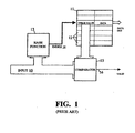
- an input 10 (for example, a 48-bit input) is to be used to retrieve data held in memory 11.
- the memory is provided with a number of locations 12 equal to, or greater than, the number of input values of interest (but less than all possible input values), and the input 10 is applied to a hashing function 13 that transforms the input 10 into a shorter length index 14 matched to the size of the memory (in the current example, this might be a 3-bit index).
- the hashing function 14 is chosen such that every input value of interest produces a unique value of the index 14 and this latter value is then used to access a corresponding location of the memory 11 - this location being that used to store the data that it is desired to associate with the input value concerned.
- each memory location stores a check value corresponding to the input value for which that data is valid.
- the check value is compared in comparator 15 with the current value of the input 10 and a data valid ouput 16 is only produced if there is a match. If the check value and input value do not match, a "miss" occurs.
- GB-A-2 148 562 discloses determining a procedure to be performed by a computer by hashing the state registers of the computer to form a number indicative of the procedure.
- a processing method in which program-controlled processing means, in the course of executing an instruction of a given type stored in memory, is caused to selectively retrieve an element from memory in dependence on the value of input data subject of the instruction; said instruction having a header identifying the instruction as of said given type, said method involving the steps of:
- the element accessed in step (d) may be used by the processing means in several different ways.
- the element may be output as a control value and used, for example, for controlling packet routing in a packet switch.
- the accessed element may be used as an indicator of the location of a next instruction to be executed by the processing means.
- a further use of the accessed element is as a return value that is returned to a prior instruction responsible for calling the instruction of said given type, the returned value being used, for example, as an index into a table associated with the prior instruction.
- the source of the input data subject of the instruction maybe implicit (for example, all such data may be provided at the same source as will generally be the case if the instruction is called by another instruction and the input data is passed as a calling parameter).
- the instruction header may include an input-selection parameter providing a source indicator for the input data (10). This source indicator may specify a memory/register location holding the input data and/or specific bits of interest of a wider input.
- the header of the instruction may include a size parameter indicative of the size of the hash table contained in the body of the instruction, this size parameter being used to limit the size, and thus the value range, ofthe offset value produced in step (b) in order to match this value to the size of the hash table.
- step (b) may be carried out using a fixed hashing function.
- the header of the instruction includes a hash control code, and the hashing of the input data is carried out in dependence on the value of this hash control code.
- step (b) involves:
- the different versions of the input data are bit-shifted versions of the input data, the number of these different versions and their respective degrees of bit shifting being determined by the hash control code.
- the combining together of the said at least portions of the different input-data versions may be carried out using an exclusive-OR operation.
- Hashing into the hash table need not be perfect and any suitable strategy, such as re-hashing, may be adopted in cases where more than one input-data value of interest hashes to the same offset value.
- apparatus comprising:
- the instruction of said given type includes a hash control code
- the hashing means comprises:
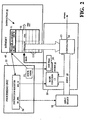
- Figure 2 illustrates a processing system comprising a processing unit 55 arranged to execute instructions held in memory 49. These instructions include an instruction to retrieve an element from memory in dependence on the value of an input 10 where only some of the input values are of interest - instruction 50 is an instruction of this type.
- Instruction 50 includes an instruction header 51 identifying the instruction type (BRANCH (HASH BODY)), and an instruction body 52 in the form of a hash table formed by a set of check-value/element pairs corresponding to respective ones of the different input values of interest. These check-value/element pairs are held in the memory locations following the instruction header 51. Retrieval of the element corresponding to an input value of interest is achieved using hashing as will now be described.
- BRANCH HASH BODY
- the instruction header 51 is passed to an instruction register 56 of the processing unit 55 when the instruction is called by the unit (an instruction address register 57 in the unit 55 holds the address of the instruction to be fetched and executed).
- the instruction header serves to identify the instruction type to the processing unit 55.
- the instruction header 51 also includes a field IN_SEL that serves to specify the source of the input 10 and the contents of this field are passed from the instruction register 56 to an input selection unit 58 which fetches the desired input.
- the instruction header further includes a field specifying an index width (IND_W) which is passed to a hashing functional block 13.
- Block 13 generates an offset index 14 which is added in unit 60 to the base address represented by the address in memory of the instruction 50; the result is then used to access the corresponding memory location and retrieve the check-value/element pair held therein. If the retrieved check-value and current input value match, the corresponding element is output; otherwise a miss is reported. How the output element is used may be specified in the instruction header or it may be coded into the element itself; typically, the element will be an action to be executed, a return value, or a jump instruction to the processing unit 55.
- index width parameter IND_W The purpose of the index width parameter IND_W is to match the size of the index 14 (and thus the number of possible memory locations it can point to) to the size of the hash table body 51 of the corresponding instruction 50.
- the block 13, the unit 60 and the comparator 15 may be considered as forming a hashing unit 59 of the Figure 2 processing system.
- FIG 3 illustrates an application of the Figure 2 processing system to the control of a packet switch; as will be appreciated by persons skilled in the art, the illustrated switch has been simplified, this being done to facilitate an understanding of the operation of the Figure 2 processing system in the context of the switch.
- the switch has two ports A and B for receiving and sending packets.
- the ports are inter-connected by a bus 75 over which received packets can be passed between the ports.
- the bus 75 also connects to a controller 70.
- the role of the controller 70 is to route incoming packets received at the ports A and B by instructing each port as to which packets are to be output by that port.
- the controller makes its routing decision for a packet based on the packet destination address contained in the packet header (in the present example, this destination address is a 16 bit address), and a two-bit port identifier identifying the port on which the packet was received (for example, port A may be designated by a binary value of "01" and port B by a binary value of "10").
- This information is made available to the controller 70 by arranging for each port to pre-append the corresponding port identifier to each packet header before putting the packet on the internal bus 75, the packet header and pre-appended port identifier then being received off the bus 75 by the controller and stored in an input register 71 (in practice, a queuing arrangement would be used).
- the controller After the controller has made its routing decision, it places the result in an output register 72 from where it is passed to the ports to determine which port, if any, will output the packet.
- controller 70 comprises the Figure 2 processing unit 55, instruction memory 49, hashing unit 59 and input select unit 58.
- Operation of the controller will first be considered in respect of the sequence of three instructions shown in Figure 4, these instructions being held in memory 49. All three instructions have an instruction header and an instruction body; however, only the second and third instructions are of the BRANCH (HASH BODY) type described above.
- the first instruction is also a BRANCH instruction but its body contains a simple lookup table indexed into directly by the value of the input quantity specified by an IN_SEL parameter contained in the instruction header; this instruction is designated as being of a type BRANCH (TABLE BODY).
- the header of the first instruction also contains the IND_W parameter that has the same function as for the BRANCH (HASH BODY) instruction 50.
- the first instruction is used to look at the two port-identifier bits of the packet information held in input register 71 (IN_SEL parameter set to PORT).
- the port identifier will have a value of "1" or "2" and results in a corresponding one of the instruction-body memory locations being accessed.
- the instruction-body table is sized to store four outcomes at corresponding locations ⁇ 0 ⁇ to ⁇ 3 ⁇ although only two are actually required in the present example. In fact, because in the present case each memory word can hold two outcomes, only two memory words are used for the four possible outcomes (thus the parameter IND_W only has a value of one, indicating a table size of two memory words). It should also be noted that the numbers given in the instruction examples of Figures 4 and 5 are in hexadecimal notation.
- the outcomes stored in the body of the first instruction indicate which of the second and third instructions should now be executed. More particularly, if the port identifier has a value of "1" then the accessed outcome will be the address ⁇ 0007> of the second instruction, whereas if the port identifier has a value "2" the accessed outcome will be the address ⁇ 000F> of the third instruction.
- the processing unit 55 takes the accessed address and retrieves the corresponding instruction.
- the jumped-to one of the second and third instructions looks at the sixteen destination address bits held in register 71 (IN_SEL set to DA) and hashes them (using hashing unit 59) to provide an offset index for accessing into the hash table body.
- there are only two destinaton addresses of interest namely the address ⁇ 0002> for packets received on port A and the address ⁇ FFF1> for packets received on port B.
- a hash-table "hit" results in the output of a port action instruction (ACTION 1 or ACTION 2 in the current example) which is stored under the control of the processing unit 55 in the output register 72 to determine routing of the packet. If no "hit" is achieved, the output register is not set and the packet is not forwarded.
- the instruction sequence of Figure 4 uses a respective hash table for each port. Whilst the BRANCH (HASH BODY) is a compact way of handling the large range of potential destination address values, where the number of addresses of interest is large (thousands rather than the two of the Figure 4 example), it is preferable to list the addresses only once, that is, to have only one BRANCH (HASH BODY) instruction rather than two. This can be achieved by treating the instruction as a called function that returns a lookup table index as will now be described with reference to the instruction sequence of Figure 5.
- BRANCH HASH BODY
- the first instruction is the same as in the Figure 4 sequence, namely a BRANCH (TABLE BODY) instruction that looks at the port identifier bits and executes a jump to the second or third instruction in dependence on the value of the port identifier.
- the second and third instructions are also BRANCH (TABLE BODY) instructions - these instructions contain the specific actions to be posted to the output register 72 for the specific destination addresses of interest for packets received at ports A and B respectively.
- the index into the table body of each of the second and third instructions is provided by the input source indicated by the IN_SEL parameter.
- the IN-SEL parameter is set to CALL ⁇ 000F> for both instructions to indicate that the index to be used is the value returned from calling the instruction located at address ⁇ 000F>.
- This called instruction (the fourth instruction of Figure 5) is a BRANCH (HASH BODY) instruction that hashes the destination address bits to provide an offset into its hash table body.
- the hash table body contains the return values to be returned to the calling instruction.
- the address ⁇ 0002> results in a value of "1" being returned whilst the address value ⁇ FFF1> results in the value "2" being returned.
- a hash table "miss" will result in a null value being returned.
- the process of suspending the operation of the calling instruction whilst the called instruction is executed is effected in standard manner using a stack onto which and from which appropriate parameters of operation are pushed and popped.
- Figure 6 illustrates a variant on the Figure 2 form of processing system in which the hash function used by the hashing functional block 13 is controlled by a hash control code (HCC) 20 included in the header 51 of each branch instruction whose body is in the form of a hash table.
- HCC hash control code
- the hash control code is passed to the block 13 to determine parameters of the hash function to be used for hashing the input data subject of the instruction.
- the hashing function can be controlled, it can be adapted to suit different search space problems (that is, to suit situations that differ one from another in terms of the characteristics of the input relative to the number and identity of the input values of interest), the index 14 produced by block 13 being applied to an appropriately-sized memory space relevant to the current input.
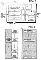
- Figure 7 illustrate the principle of operation of one form of the block 13 suitable for use in the Figure 6 system.
- the Figure 7 block 13 comprises a combining block 22 and a bit selection block 23.
- the combining block 22 serves to form an intermediate value 27 (termed a "transformed value” below) by combining together, in exclusive-OR block 26, different bit-shifted versions 25A, 25B and 25C of the input 10; the number and degree of bit shifting of these input versions 25 is determined by the hash control code 20.
- the bit-selection block then forms the index 14 by selecting bits from the transformed value 27, the number of these bits being determined by an index-width parameter 21 (which effectively specifies the size of the memory space to be accessed by index 14).
- the combining block 22 has the potential to create (at least notionally, if not explicitly) P bit-shifted versions of the input, these versions being labelled Version 0 to Version (P-1) in Figure 8. These versions are progessively further bit shifted right by increments of one bit from Version 0 to Version (P-1) with Version 0 being right shifted (-1) relative to the original input 10 (that is, left-shifted by 1). In the present example, the input is shifted and not circulated to form the input Versions 0 to (P-1) with zero values being added to fill otherwise undefined bit positions outside of the input sequence.
- the hash control code 20 has P bits extending from bit position 0 to position P-1. If the code 20 has a "1" in a particular bit position, then the corresponding input version is presented to XOR block 26 for combination with other versions so presented. For example, if bit positions 2, 7 and 9 of the code 20 are “1"s and all other positions "0", then input Versions 2, 7 and 9 (corresponding to right shifts of 1 bit, 6 bits and 8 bits respectively), are combined in the XOR block 26 to form the intermediate transformed value 27.
- Figure 9 illustrates circuitry for effecting version selection and combination for generating one bit (the bit in bit position "n") of the transformed value 27. More particularly, the hash control code is held in register 32 and each bit is used to control a corresponding two-input AND gate 30; the outputs of all the gates 30 are fed to an XOR gate 31. The other input of each gate 30 receives bit "n" of the input Version that corresponds to the hash control code bit controlling that gate (bit 0 being the first bit position in each version). These bit “n” values for all input versions can be simply derived by tapping appropriate cells of a register 33 that holds the input 10 padded each end with zero bits. Thus bit “n” of input version "m” is bit (m+n-1) of input 10.
- the Figure 9 circuitry other than registers 32, 33, is repeated for each bit of the transformed value (which may, for example, be a 16-bit value).
- bit-selection block 23 in the present example this takes bit 1 to bit (index-width) of the transformed value, and outputs them as the index 14. More complex selection patterns may alternatively be used. Suitable circuitry for implementing block 23 will be apparent to persons skilled in the art.
- a hash control code of 'h1dbb764747a (where 'h indicates hexadecimal notation) and an index width of 3 will discriminate between the following six 48-bit input values:
- the hash control code provides a convenient and flexible way of providing a very large number of different hash functions. Determination of the hash control code needed to produce the hash function best suited for a particular purpose (for example, for achieving perfect hashing within the minimum memory space) can be determined by an automated trial and error process. Once the desired hash control code has been determined, then it can be applied to the hashing functional block 13 whenever a relevant input 10 is received. At the same time, the appropriate index width input 23 is also provided.
- trial and error determination of a suitable hash control code could potentially take a long time and it is therefore convenient to take steps to improve the chances of success if trial and error does not produce a successful result after a given number of tries.
- the size of the index width can be increased to give a larger target (the penalty being that more memory will be required).
- Another approach is to allow re-hashing - that is, not always to seek to achieve perfect hashing but to allow for input values of interest to hash to the same index (and thus memory location) with only one of these values being validated - any non-validated accesses to a memory location giving rise to a re-hash using a different hash function.
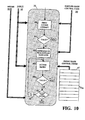
- steps 40 to 46 within box 38 represent the overall hashing process. More particularly, at step 40 a first memory access attempt is made on the input 10 using the supplied hash control code 20 (and index width, this latter not being illustrated as it is constant for the whole hashing process). At step 41, the validity of the memory access attempt is checked by comparing the input 10 with the check value stored in the accessed location; if validated (a "hit") the hashing process is exited.
- a new memory access attempt is made using a hash control control code selected from a set 47 of predetermined codes; the identity of the chosen code is given by determining (step 42) the value of an index idx into the set 47 on the basis of the terminating bits of the supplied hash control code 20.
- a new access attempt is made (step 43) and its validity is checked (step 44). If a "hit" is achieved, the hashing process is exited; otherwise, the value of idx is incremented (step 46) and a further retry is made with the new predetermined hash control code pointed to by idx.
- the number of retries permitted is limited by a retry value 39, the current number of retries being tested against this value 39 in step 45 (it being understood that a count is kept of the number of retries). If a "hit” is not achieved after the maximum number of retries permitted, a "miss” is output to indicate that the input value was not one of interest, and the hashing process exited. It will be appreciated that the initial hash control code 20, the index width and the number of permitted retries are chosen to ensure that all input values of interest will result in a "hit").
- the source of input data for the BRANCH (HASH BODY) instruction may be implicit rather than explicitly specified by the IN-SEL parameter.
- the hash control code of Figures 6 to 10 has been described as controlling the number and degree of bit-shifting of the input versions 25, additional or different parameters of the hashing function could be controlled.
- the hashing control code could include bits for specifying the function used to combine the input versions (multiplication of the versions, etc), and/or for specifying circulation rather than shifting of the input, and/or for specifying the direction and magnitude of shifting/circulation between versions, and/or the ordering of the bits slected by bit-selection block 23, etc.
- bit selection function of the bit-selection block 23 can be implemented within the Figure 4 form of the combining unit 22 by disabling those instances of the gating circuity (elements 30, 31) related to bits of the transformed value that are not required for the current index.
- each hash code could be computed from the current one using some kind of XORing function.
Landscapes
- Engineering & Computer Science (AREA)
- Software Systems (AREA)
- Theoretical Computer Science (AREA)
- Physics & Mathematics (AREA)
- General Engineering & Computer Science (AREA)
- General Physics & Mathematics (AREA)
- Information Retrieval, Db Structures And Fs Structures Therefor (AREA)
Claims (18)
- Procédé de traitement selon lequel un moyen de traitement commandé par programme (59) lors de l'exécution d'une instruction (50) d'un type donné stockée en mémoire (49) est amené à extraire, de façon sélective, un élément de la mémoire (49) selon la valeur de données d'entrée (10) concernant l'instruction, ladite instruction possédant une en-tête (51) identifiant l'instruction comme étant dudit type donné, procédé comprenant les étapes suivantes :a) la détermination du fait qu'une instruction en cours (50) devant être exécutée par le moyen de traitement (59) est dudit type donné ;b) lorsque l'étape a) détermine que l'instruction (50) est dudit type donné, l'utilisation desdites données d'entrée (10) concernant l'instruction pour produire une valeur de décalage (14) ; etc) l'utilisation de la valeur de décalage (14) produite lors de l'étape b) pour accéder à un élément en mémoire par rapport à la position en mémoire de l'instruction en cours ;
caractérisé en ce que :l'instruction dudit type donné comprend un corps (52) sous la forme d'une table de hachage possédant au moins une entrée avec à la fois 1) une valeur de contrôle correspondant à une valeur en question desdites données d'entrée concernant l'instruction et 2) un élément devant être utilisé lorsque lesdites données d'entrée ont ladite valeur en question ;lors de l'étape b), ladite entrée est hachée pour produire ladite valeur de décalage qui est alors utilisée à l'étape c) pour accéder à une entrée correspondante dans la table de hachage de l'instruction en cours ; etle procédé comprend l'étape supplémentaire suivante :d) la comparaison de la valeur des données d'entrée (10) avec la valeur de contrôle conservée dans l'entrée lue lors de l'étape c) et la disponibilité de l'élément d'entrée associé pour une utilisation fonctionnelle seulement lorsque les valeurs comparées correspondent. - Procédé selon la revendication 1, comprenant, de plus, l'utilisation d'un dit élément rendu disponible à l'étape d) pour la commande de l'acheminement par paquets dans un commutateur de paquets.
- Procédé selon la revendication 1, comprenant, de plus, l'utilisation d'un dit élément rendu disponible à l'étape d) comme indicateur de la position d'une instruction suivante devant être exécutée par le moyen de traitement (59).
- Procédé selon la revendication 1, comprenant, de plus, l'utilisation d'un dit élément rendu disponible à l'étape d) comme valeur de retour qui est renvoyée à une instruction précédente responsable de l'appel de l'instruction dudit type donné.
- Procédé selon la revendication 4, selon lequel ladite valeur de retour est utilisée par ladite instruction précédente comme index dans une table associée à ladite instruction précédente.
- Procédé selon la revendication 1, selon lequel l'en-tête (51) de ladite instruction 50 comprend un paramètre de sélection d'entrée (IN_SEL) fournissant un indicateur de source pour lesdites données d'entrée (10), ledit procédé impliquant l'utilisation du paramètre de sélection d'entrée pour accéder aux données d'entrée devant être hachées à l'étape b).
- Procédé selon la revendication 1, selon lequel l'en-tête (51) de ladite instruction 50 comprend un paramètre de dimension (IND_W) indiquant la taille de la table de hachage contenue dans le corps (52) de l'instruction, ledit procédé impliquant l'utilisation du paramètre de taille afin de limiter la taille et ainsi, l'intervalle de valeur de ladite valeur de décalage (14) pour accorder la taille de la table de hachage.
- Procédé selon la revendication 1, selon lequel le hachage des données d'entrée (10) à l'étape b) est effectué à l'aide d'une fonction de hachage fixée.
- Procédé selon la revendication 1, selon lequel l'en-tête (51) de ladite instruction 50 comprend un code de commande de hachage (20) et le hachage des données d'entrée (10) à l'étape b) est effectué selon la valeur dudit code de commande de hachage.
- Procédé selon la revendication 9, selon lequel l'étape b) comprend :la formation d'une valeur transformée (27) par combinaison d'au moins des parties des différentes versions (25) desdites données d'entrée, le code de commande de hachage (20) servant à établir des paramètres spécifiques de cette formation ; etl'utilisation de ladite valeur transformée (27) pour constituer ladite valeur de décalage (14).
- Procédé selon la revendication 10, selon lequel lesdites différentes versions (25) des données d'entrée sont des versions à décalage binaire des données d'entrée (10), le nombre desdites différentes versions et leurs degrés respectifs de décalage binaire étant déterminés par ledit code de commande de hachage (20).
- Procédé selon la revendication 11, selon lequel ledit code de commande de hachage (20) est un code à plusieurs bits, l'état de chacun d'au moins certains des bits du code de commande de hachage déterminant la présence ou l'absence d'une dite version (25) des données d'entrée correspondant au décalage binaire des données d'entrée d'une valeur dépendant de la position du bit attenant de code de commande de hachage dans ce code.
- Procédé selon l'une quelconque des revendications précédentes, selon lequel lesdites au moins certaines parties des différentes versions desdites données d'entrée sont combinées selon une opération logique de OU-EXCLUSIF (26).
- Procédé selon l'une quelconque des revendications précédentes, selon lequel dans les cas où l'utilisation d'une fonction de hachage initiale pour effectuer le hachage de l'étape b) entraíne plus d'une valeur en question desdites données d'entrée (10) hachant sur la même valeur de décalage, dans l'éventualité d'une entrée correspondante de table de hachage contenant une valeur de contrôle ne correspondant pas à la valeur de données d'entrée à l'étape d), au moins un essai supplémentaire de hachage est alors effectué à l'aide d'une fonction de hachage différente de ladite fonction de hachage initiale.
- Dispositif comprenant :caractérisé en ce que le dispositif est prévu pour traiter une dite instruction dudit type donné, une telle instruction comprenant un corps (52) sous la forme d'une table de hachage possédant au moins une entrée avec à la fois 1) une valeur de contrôle correspondant à une valeur en question des données d'entrée soumises à l'instruction et 2) un élément devant être utilisé par ladite instruction lorsque lesdites données d'entrée possèdent ladite valeur en question, le dispositif étant prévu pour traiter une telle instruction par :un moyen de stockage (49) pour stocker un programme comprenant une instruction (50) d'un type donné selon une identification dans une en-tête (51) de l'instruction ;un moyen de traitement (55) pour exécuter ledit programme dans ledit moyen de stockage (49) ;un moyen (58) pour fournir des données d'entrée (10) ;un moyen de détermination de décalage, lors du traitement de ladite instruction dudit type donné par le moyen de traitement, pour utiliser lesdites données d'entrée (10) afin de produire une valeur de décalage (14) ; etun moyen d'accès à décalage (60) pour utiliser ladite valeur de décalage afin d'accéder audit moyen de stockage avec un décalage par rapport à la position de l'instruction en cours exécutée par le moyen de traitement ;le moyen de détermination de décalage comprenant un moyen de hachage (13) pour hacher lesdites données d'entrée (10) afin de produire ladite valeur de décalage (14) ;la prévision d'un moyen de comparateur (15) prévu, lors d'un accès à une entrée de table de hachage par ledit moyen d'accès à décalage lors de l'exécution d'une instruction dudit type donné par le moyen de traitement (55), pour comparer la valeur de données d'entrée avec la valeur de contrôle de l'entrée de table de hachage et pour provoquer la sortie de l'élément correspondant de table de hachage lorsque la valeur des données d'entrée et la valeur de contrôle correspondent.
- Dispositif selon la revendication 15, dans lequel, pour le traitement d'une dite instruction dudit type donné comprenant un code de commande de hachage, le moyen de hachage (13) comprend :un moyen prévu lors de l'exécution de ladite instruction par le moyen de traitement (55) pour recevoir lesdites données d'entrée (10) et ledit code de commande de hachage (20) ;un moyen (22) pour former une valeur transformée (27) par combinaison d'au moins des parties correspondantes de plusieurs versions à décalage binaire (25) desdites données d'entrée, le nombre de telles versions et leurs degrés respectifs de décalage binaire étant déterminés par ledit code de commande de hachage (20) ; etun moyen (23) pour utiliser ladite valeur transformée (27) afin de fournir ladite valeur de décalage (14).
- Dispositif selon la revendication 16, dans lequel lesdites différentes versions (25) des données d'entrée sont des versions à décalage binaire des données d'entrée (10), le nombre desdites différentes versions et leurs degrés respectifs de décalage binaire étant déterminés par ledit code de commande de hachage (20), ledit moyen de formation d'une valeur transformée comprenant :un premier moyen de registre (33) pour stocker lesdites données d'entrée (10), le premier moyen de registre étant accessible sur sa longueur de façon à permettre l'accès auxdites versions (25) selon un accès adapté à décalage dans le premier moyen de registre ;un second moyen de registre (32) pour stocker ledit code de commande de hachage (20) ;un moyen logique de OU-EXCLUSIF (31) ; etun moyen de porte logique (30) connecté auxdits premier et second moyens de registre (33, 32) pour commander le passage dans ledit moyen logique de OU-EXCLUSIF (31) de bits desdites différentes versions (25) de l'entrée selon la valeur du code de commande de hachage (20), la sortie dudit moyen logique de OU-EXCLUSIF (31) constituant ladite valeur transformée (27).
- Dispositif selon l'une quelconque des revendications 15 à 17, dans lequel le programme comprenant ladite instruction (50) du type donné est stocké dans le moyen de stockage (49).
Priority Applications (3)
| Application Number | Priority Date | Filing Date | Title |
|---|---|---|---|
| EP98303431A EP0953897B1 (fr) | 1998-05-01 | 1998-05-01 | Instruction de processeur avec hashing |
| DE69816784T DE69816784T2 (de) | 1998-05-01 | 1998-05-01 | Prozessorbefehl mit Hashcodierung |
| US09/303,460 US6272614B1 (en) | 1998-05-01 | 1999-04-30 | Processing method and apparatus involving a processor instruction using hashing |
Applications Claiming Priority (1)
| Application Number | Priority Date | Filing Date | Title |
|---|---|---|---|
| EP98303431A EP0953897B1 (fr) | 1998-05-01 | 1998-05-01 | Instruction de processeur avec hashing |
Publications (2)
| Publication Number | Publication Date |
|---|---|
| EP0953897A1 EP0953897A1 (fr) | 1999-11-03 |
| EP0953897B1 true EP0953897B1 (fr) | 2003-07-30 |
Family
ID=8234805
Family Applications (1)
| Application Number | Title | Priority Date | Filing Date |
|---|---|---|---|
| EP98303431A Expired - Lifetime EP0953897B1 (fr) | 1998-05-01 | 1998-05-01 | Instruction de processeur avec hashing |
Country Status (3)
| Country | Link |
|---|---|
| US (1) | US6272614B1 (fr) |
| EP (1) | EP0953897B1 (fr) |
| DE (1) | DE69816784T2 (fr) |
Cited By (6)
| Publication number | Priority date | Publication date | Assignee | Title |
|---|---|---|---|---|
| US7225281B2 (en) | 2001-08-27 | 2007-05-29 | Intel Corporation | Multiprocessor infrastructure for providing flexible bandwidth allocation via multiple instantiations of separate data buses, control buses and support mechanisms |
| US7246197B2 (en) | 2001-08-27 | 2007-07-17 | Intel Corporation | Software controlled content addressable memory in a general purpose execution datapath |
| US7337275B2 (en) | 2002-08-13 | 2008-02-26 | Intel Corporation | Free list and ring data structure management |
| US7418571B2 (en) | 2003-01-10 | 2008-08-26 | Intel Corporation | Memory interleaving |
| US7487505B2 (en) | 2001-08-27 | 2009-02-03 | Intel Corporation | Multithreaded microprocessor with register allocation based on number of active threads |
| US7610451B2 (en) | 2002-01-25 | 2009-10-27 | Intel Corporation | Data transfer mechanism using unidirectional pull bus and push bus |
Families Citing this family (7)
| Publication number | Priority date | Publication date | Assignee | Title |
|---|---|---|---|---|
| SE9904685D0 (sv) | 1999-12-17 | 1999-12-17 | Switchcore Ab | A programmable packet decoder |
| JP3729064B2 (ja) * | 2000-11-29 | 2005-12-21 | 日本電気株式会社 | データ依存関係検出装置 |
| CN100533410C (zh) * | 2001-08-27 | 2009-08-26 | 英特尔公司 | 通用执行数据通路中软件控制的内容可寻址存储器 |
| US7111305B2 (en) * | 2002-10-31 | 2006-09-19 | Sun Microsystems, Inc. | Facilitating event notification through use of an inverse mapping structure for subset determination |
| US20040103399A1 (en) * | 2002-11-22 | 2004-05-27 | Manisha Agarwala | Data trace compression map |
| US20080317245A1 (en) * | 2007-06-20 | 2008-12-25 | Franny Wei | Hash function implemention with ROM and CSA |
| JP2021157604A (ja) * | 2020-03-27 | 2021-10-07 | 株式会社村田製作所 | データ通信装置、データ通信モジュール |
Family Cites Families (5)
| Publication number | Priority date | Publication date | Assignee | Title |
|---|---|---|---|---|
| GB2148652B (en) | 1983-09-15 | 1987-09-09 | Sinclair Res Ltd | Television receivers |
| GB8327567D0 (en) * | 1983-10-14 | 1983-11-16 | Gen Electric Co Plc | Computers |
| US5170475A (en) * | 1989-03-06 | 1992-12-08 | Motorola, Inc. | Data processor having instructions for interpolating between memory-resident data values respectively |
| US5333283A (en) * | 1991-10-29 | 1994-07-26 | International Business Machines Corporation | Case block table for predicting the outcome of blocks of conditional branches having a common operand |
| US5754806A (en) * | 1995-11-03 | 1998-05-19 | Holtek Microelectronics, Inc. | Memory table look-up device and method |
-
1998
- 1998-05-01 DE DE69816784T patent/DE69816784T2/de not_active Expired - Lifetime
- 1998-05-01 EP EP98303431A patent/EP0953897B1/fr not_active Expired - Lifetime
-
1999
- 1999-04-30 US US09/303,460 patent/US6272614B1/en not_active Expired - Lifetime
Cited By (6)
| Publication number | Priority date | Publication date | Assignee | Title |
|---|---|---|---|---|
| US7225281B2 (en) | 2001-08-27 | 2007-05-29 | Intel Corporation | Multiprocessor infrastructure for providing flexible bandwidth allocation via multiple instantiations of separate data buses, control buses and support mechanisms |
| US7246197B2 (en) | 2001-08-27 | 2007-07-17 | Intel Corporation | Software controlled content addressable memory in a general purpose execution datapath |
| US7487505B2 (en) | 2001-08-27 | 2009-02-03 | Intel Corporation | Multithreaded microprocessor with register allocation based on number of active threads |
| US7610451B2 (en) | 2002-01-25 | 2009-10-27 | Intel Corporation | Data transfer mechanism using unidirectional pull bus and push bus |
| US7337275B2 (en) | 2002-08-13 | 2008-02-26 | Intel Corporation | Free list and ring data structure management |
| US7418571B2 (en) | 2003-01-10 | 2008-08-26 | Intel Corporation | Memory interleaving |
Also Published As
| Publication number | Publication date |
|---|---|
| DE69816784T2 (de) | 2004-04-15 |
| US6272614B1 (en) | 2001-08-07 |
| EP0953897A1 (fr) | 1999-11-03 |
| DE69816784D1 (de) | 2003-09-04 |
Similar Documents
| Publication | Publication Date | Title |
|---|---|---|
| US6272614B1 (en) | Processing method and apparatus involving a processor instruction using hashing | |
| US7032100B1 (en) | Simple algorithmic cryptography engine | |
| US4882701A (en) | Lookahead program loop controller with register and memory for storing number of loop times for branch on count instructions | |
| US4972315A (en) | Data flow machine | |
| EP0125855B1 (fr) | Système de commande de mémoire tampon | |
| US7979679B2 (en) | System and method for selectively controlling operations in lanes in an execution unit of a computer | |
| US10997140B2 (en) | Method and apparatus for acceleration of hash-based lookup | |
| US5657484A (en) | Method for carrying out a boolean operation between any two bits of any two registers | |
| EP0953919B1 (fr) | Méthode et dispositif de calcul aléatoire d'adresses (hashing) | |
| US5490259A (en) | Logical-to-real address translation based on selective use of first and second TLBs | |
| US20090171651A1 (en) | Sdram-based tcam emulator for implementing multiway branch capabilities in an xml processor | |
| JP3789320B2 (ja) | ベクトル処理装置及び該装置を用いた追い越し制御方法 | |
| US20010007559A1 (en) | Interleaved processing system for processing frames within a network router | |
| JP2000020396A (ja) | 可変式キャッシュ方式 | |
| US7047400B2 (en) | Single array banked branch target buffer | |
| US5404533A (en) | Language processing system for converting a source program into a computer executable machine language | |
| US7610440B2 (en) | Content addressable memory with automated learning | |
| US11537522B2 (en) | Determining a tag value for use in a tag-guarded memory | |
| JP2629613B2 (ja) | 分岐予測装置 | |
| US20030097540A1 (en) | Data-driven type information processing apparatus and information processing method allowing for effective use of memory | |
| JPH0731635B2 (ja) | 情報処理装置 | |
| JPH0239325A (ja) | マイクロ・シーケンス制御方式 | |
| JPH0553916A (ja) | アドレス変換装置 | |
| JPS61216034A (ja) | デ−タ処理装置 | |
| JPH05342097A (ja) | インターリーブ装置 |
Legal Events
| Date | Code | Title | Description |
|---|---|---|---|
| PUAI | Public reference made under article 153(3) epc to a published international application that has entered the european phase |
Free format text: ORIGINAL CODE: 0009012 |
|
| AK | Designated contracting states |
Kind code of ref document: A1 Designated state(s): DE FR GB |
|
| AX | Request for extension of the european patent |
Free format text: AL;LT;LV;MK;RO;SI |
|
| 17P | Request for examination filed |
Effective date: 20000321 |
|
| AKX | Designation fees paid |
Free format text: DE FR GB |
|
| RAP1 | Party data changed (applicant data changed or rights of an application transferred) |
Owner name: HEWLETT-PACKARD COMPANY, A DELAWARE CORPORATION |
|
| 17Q | First examination report despatched |
Effective date: 20020402 |
|
| GRAH | Despatch of communication of intention to grant a patent |
Free format text: ORIGINAL CODE: EPIDOS IGRA |
|
| GRAH | Despatch of communication of intention to grant a patent |
Free format text: ORIGINAL CODE: EPIDOS IGRA |
|
| GRAA | (expected) grant |
Free format text: ORIGINAL CODE: 0009210 |
|
| AK | Designated contracting states |
Designated state(s): DE FR GB |
|
| REG | Reference to a national code |
Ref country code: GB Ref legal event code: FG4D |
|
| REF | Corresponds to: |
Ref document number: 69816784 Country of ref document: DE Date of ref document: 20030904 Kind code of ref document: P |
|
| ET | Fr: translation filed | ||
| PLBE | No opposition filed within time limit |
Free format text: ORIGINAL CODE: 0009261 |
|
| STAA | Information on the status of an ep patent application or granted ep patent |
Free format text: STATUS: NO OPPOSITION FILED WITHIN TIME LIMIT |
|
| 26N | No opposition filed |
Effective date: 20040504 |
|
| PGFP | Annual fee paid to national office [announced via postgrant information from national office to epo] |
Ref country code: FR Payment date: 20110607 Year of fee payment: 14 |
|
| PGFP | Annual fee paid to national office [announced via postgrant information from national office to epo] |
Ref country code: GB Payment date: 20110525 Year of fee payment: 14 |
|
| PGFP | Annual fee paid to national office [announced via postgrant information from national office to epo] |
Ref country code: DE Payment date: 20110527 Year of fee payment: 14 |
|
| REG | Reference to a national code |
Ref country code: GB Ref legal event code: 732E Free format text: REGISTERED BETWEEN 20120329 AND 20120404 |
|
| GBPC | Gb: european patent ceased through non-payment of renewal fee |
Effective date: 20120501 |
|
| REG | Reference to a national code |
Ref country code: FR Ref legal event code: ST Effective date: 20130131 |
|
| REG | Reference to a national code |
Ref country code: DE Ref legal event code: R119 Ref document number: 69816784 Country of ref document: DE Effective date: 20121201 |
|
| PG25 | Lapsed in a contracting state [announced via postgrant information from national office to epo] |
Ref country code: FR Free format text: LAPSE BECAUSE OF NON-PAYMENT OF DUE FEES Effective date: 20120531 Ref country code: GB Free format text: LAPSE BECAUSE OF NON-PAYMENT OF DUE FEES Effective date: 20120501 |
|
| PG25 | Lapsed in a contracting state [announced via postgrant information from national office to epo] |
Ref country code: DE Free format text: LAPSE BECAUSE OF NON-PAYMENT OF DUE FEES Effective date: 20121201 |