EP0954040B1 - Dispositif de sécurité et batterie secondaire utilisant un tel dispositif - Google Patents
Dispositif de sécurité et batterie secondaire utilisant un tel dispositif Download PDFInfo
- Publication number
- EP0954040B1 EP0954040B1 EP99303274A EP99303274A EP0954040B1 EP 0954040 B1 EP0954040 B1 EP 0954040B1 EP 99303274 A EP99303274 A EP 99303274A EP 99303274 A EP99303274 A EP 99303274A EP 0954040 B1 EP0954040 B1 EP 0954040B1
- Authority
- EP
- European Patent Office
- Prior art keywords
- thin plate
- safety device
- plate
- pressure chamber
- reference pressure
- Prior art date
- Legal status (The legal status is an assumption and is not a legal conclusion. Google has not performed a legal analysis and makes no representation as to the accuracy of the status listed.)
- Expired - Lifetime
Links
Images



Classifications
-
- G—PHYSICS
- G01—MEASURING; TESTING
- G01L—MEASURING FORCE, STRESS, TORQUE, WORK, MECHANICAL POWER, MECHANICAL EFFICIENCY, OR FLUID PRESSURE
- G01L19/00—Details of, or accessories for, apparatus for measuring steady or quasi-steady pressure of a fluent medium insofar as such details or accessories are not special to particular types of pressure gauges
- G01L19/08—Means for indicating or recording, e.g. for remote indication
- G01L19/12—Alarms or signals
-
- H—ELECTRICITY
- H01—ELECTRIC ELEMENTS
- H01H—ELECTRIC SWITCHES; RELAYS; SELECTORS; EMERGENCY PROTECTIVE DEVICES
- H01H35/00—Switches operated by change of a physical condition
- H01H35/24—Switches operated by change of fluid pressure, by fluid pressure waves, or by change of fluid flow
-
- H—ELECTRICITY
- H01—ELECTRIC ELEMENTS
- H01M—PROCESSES OR MEANS, e.g. BATTERIES, FOR THE DIRECT CONVERSION OF CHEMICAL ENERGY INTO ELECTRICAL ENERGY
- H01M50/00—Constructional details or processes of manufacture of the non-active parts of electrochemical cells other than fuel cells, e.g. hybrid cells
- H01M50/50—Current conducting connections for cells or batteries
- H01M50/572—Means for preventing undesired use or discharge
- H01M50/574—Devices or arrangements for the interruption of current
-
- H—ELECTRICITY
- H01—ELECTRIC ELEMENTS
- H01M—PROCESSES OR MEANS, e.g. BATTERIES, FOR THE DIRECT CONVERSION OF CHEMICAL ENERGY INTO ELECTRICAL ENERGY
- H01M50/00—Constructional details or processes of manufacture of the non-active parts of electrochemical cells other than fuel cells, e.g. hybrid cells
- H01M50/50—Current conducting connections for cells or batteries
- H01M50/572—Means for preventing undesired use or discharge
- H01M50/574—Devices or arrangements for the interruption of current
- H01M50/578—Devices or arrangements for the interruption of current in response to pressure
-
- Y—GENERAL TAGGING OF NEW TECHNOLOGICAL DEVELOPMENTS; GENERAL TAGGING OF CROSS-SECTIONAL TECHNOLOGIES SPANNING OVER SEVERAL SECTIONS OF THE IPC; TECHNICAL SUBJECTS COVERED BY FORMER USPC CROSS-REFERENCE ART COLLECTIONS [XRACs] AND DIGESTS
- Y02—TECHNOLOGIES OR APPLICATIONS FOR MITIGATION OR ADAPTATION AGAINST CLIMATE CHANGE
- Y02E—REDUCTION OF GREENHOUSE GAS [GHG] EMISSIONS, RELATED TO ENERGY GENERATION, TRANSMISSION OR DISTRIBUTION
- Y02E60/00—Enabling technologies; Technologies with a potential or indirect contribution to GHG emissions mitigation
- Y02E60/10—Energy storage using batteries
Definitions
- the present invention relates to a safety device for maintaining the safety of an apparatus by cutting off a current flow path in response to pressure buildup inside the apparatus.
- the invention relates to a safety device for use in smaller size apparatuses such as rechargeable secondary batteries, typically lithium ion batteries, with an imperative need for size reduction.
- the invention relates to a secondary battery using such a safety device.
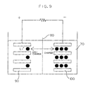
- Fig. 9 is a schematic diagram illustrating the basic construction of a conventional lithium ion battery.
- the lithium ion battery has such a simple construction that a positive electrode 90 and a negative electrode 100 are disposed in an electrolytic solution 70 of an organic solvent with a separator 80 interposed therebetween. Migration of Li ions between the positive electrode 90 and the negative electrode 100 causes the battery to be charged and discharged. Lithium oxide is employed for the positive electrode 90, and a carbon compound is employed for the negative electrode 100.
- the secondary battery offers high performance.
- a gas evolves due to decomposition of the electrolytic solution thereby to increase the inside pressure of the battery. In the worst case, this results in explosion of the battery. Therefore, batteries of this type are provided with various types of safety devices.
- the safety devices are generally classified into two types, i.e., safety valve mechanisms and current flow interruption mechanisms.
- the safety valve mechanisms are designed such that a safety valve provided in a battery surface is opened by buildup of the battery inside pressure thereby to release the inside gas for prevention of further increase in the inside pressure.
- the current flow interruption mechanisms are adapted to cut off a conductive path by utilizing the buildup of the inside gas pressure or to cut off a conductive path in response to detection of a temperature rise caused by the pressure build-up inside the battery.
- thermosensitive element As a current flow interruption mechanism responsive to a temperature rise, a simple mechanism employing a positive temperature coefficient (PTC) element as a thermosensitive element has been put to practical use. However, there is a time lag between the buildup of the battery inside pressure and the temperature rise. Therefore, such a mechanism fails to ensure a stable operation, making it difficult to provide a highly reliable safety device.
- PTC positive temperature coefficient
- a current flow interruption mechanism responsive to the buildup of the gas pressure inside a battery is disclosed, for example, in Japanese Unexamined Patent Publication (KOKAI) No. 9-55197 (1997).
- the mechanism includes a pressure-responsive displacement member adapted to be displaced by the increase in the battery inside pressure, and is designed so that a conductive path is cut off by the displacement of the pressure-responsive displacement member.
- the conductive path, the pressure-responsive displacement member and a support member for supporting these components are required. Therefore, the mechanism has a complicated construction, presenting problems associated with the size reduction and cost reduction.
- the safety device includes a thin plate of a brittle material adapted to be ruptured by a difference between pressures exerted on opposite sides thereof, a conductive path provided on the thin plate and adapted to be cut off by the rupture of the thin plate and a spacer plate provided integrally with the thin plate on one surface thereof and having a through-hole through which a portion of the one surface of the thin plate is exposed, wherein one surface of the thin plate is present in a reference pressure chamber partly formed by the through-hole.
- the safety device is of a pressure-responsive type which is effectuated when the pressure is out of a predetermined allowable range.
- the safety device of the pressure-responsive type is preferably embodied such that the reference pressure chamber is defined by a partition wall partly constituted by the thin plate.
- the reference pressure chamber is sealed.
- a juncture between the spacer plate and the thin plate preferably has an inner corner having a curvature radius of not greater than 0.1mm.
- the reference pressure chamber is preferably sealed by a cover plate provided on a side of the spacer plate opposite from the thin plate as covering the spacer plate.
- the reference pressure chamber preferably has a major- to minor-axis length ratio of 1.0 to 1.2 as viewed in plan. This ensures the rupture of the thin plate when the pressure difference between the opposite sides thereof reaches the predetermined level.
- the brittle material may be selected from the group consisting of ceramic materials, glass materials and glass ceramic materials.
- the brittle material preferably has a Young's modulus of not lower than 60GPa and a flexural strength of 80 to 1000MPa.
- the thin plate preferably has a thickness of 10 to 100 ⁇ m.
- the thin plate is easy to handle in production thereof, and has stable rupture characteristics.
- the thin plate preferably has a thickness of 25 to 75 ⁇ m.
- the secondary battery according to the present invention includes the aforesaid safety device which is interposed between an internal electrode and an external electrode in a battery casing.
- the safety device Since the safety device has a small and simple construction, it is easy to incorporate the safety device in the battery. Thus, the secondary battery with the safety device is highly reliable with a smaller size.
- the thin plate if composed of a ceramic material, is virtually free from time-related changes, so that operational variations of the safety device can be suppressed for an extended period without provision of a special protective film on the thin plate.
- the fabrication method for the safety device includes the steps of: forming a green sheet for the thin plate from a brittle material; forming a green sheet for the spacer plate having the through-hole which later forms part of the reference pressure chamber; laminating the green sheets for the thin plate and the spacer plate into a laminate, integrally sintering the laminate and forming the conductive path on the other surface of the thin plate.
- the curvature radius of a corner of a juncture between the thin plate and the spacer plate can be reduced, and the safety device can be fabricated at lower costs.
- the fabrication method further includes the step of forming a green sheet for a cover plate and the laminating step includes laminating the green sheets for the spacer plate, the thin plate and the cover plate with the green sheet for the spacer plate being held therebetween.
- the fabrication method preferably further includes the steps of forming a through-hole in a portion of the cover plate which opposes to the reference pressure chamber and, after the sintering step, closing the through-hole to seal the reference pressure chamber.
- Figs. 1A and 1B are a perspective view and a sectional view respectively, which illustrate a safety device which does not form part of the present invention.
- the safety device 130 includes a container 10 having a recess formed in the center thereof and a thin plate 20 as a cover member which sealingly covers the mouth of the container 10.
- the thin plate 20 is composed of a brittle material and adapted to be ruptured when a difference between pressures exerted on opposite sides of the thin plate 20 exceeds a predetermined level.
- the thin plate 20 is bonded to the container 10, for example, with an adhesive.
- Examples of specific brittle materials include ceramic materials, glass materials and glass ceramic materials.
- the container 10 is not necessarily required to be composed of a ceramic material, but preferably composed of the same material as the thin plate 20 for stable attachment of the thin plate 20 to the container 10. Where the thin plate 20 and the container 10 are composed of the same ceramic material, it is also possible to fix the thin plate 20 to the container 10 in a ceramic sintering process.
- a sealed reference pressure chamber 50 is formed by covering the recess 10a of the container 10 with the thin plate 20.
- one surface of the thin plate 20 is present in the reference pressure chamber 50 so as to be subjected to the inside pressure (e.g., atmospheric pressure) of the reference pressure chamber 50.
- a conductive path 30 is formed on the other surface of the thin plate 20 not facing to the reference pressure chamber 50 by a thick film printing technique. Electrodes 40, 40 are brazed to opposite edges of the thin plate 20.
- Fig. 2 illustrates a secondary battery in which the safety device 130 shown in Figs. 1A and 1B is incorporated.
- a casing 110 is filled with an electrolytic solution 70, in which a positive electrode 90 and a negative electrode 100 as internal electrodes are immersed with a separator 80 interposed therebetween.
- the positive electrode 90 and the negative electrode 100 are actually of a plural-layer structure with the separator 80 interposed therebetween, these electrodes are schematically illustrated in Fig. 2.
- the positive electrode 90 is connected via the safety device 130 to an output portion or terminal 120 as an external electrode led out of the casing 110.
- the negative electrode 100 is electrically connected to the casing 110 via an interconnection not shown.
- the safety device 130 is provided between the output portion 120 and the positive electrode 90 in the electrolytic solution 70 within the casing 110.
- the electrodes 40, 40 connected to opposite ends of the conductive path 30 formed on the thin plate 20 of the safety device 130 are respectively connected to the output portion 120 and the positive electrode 90.
- the safety device 130 is connected to the positive electrode 90, but may be connected to the negative electrode 100.
- the secondary battery of such a construction If the secondary battery of such a construction is overcharged for some reason, a gas evolves inside the battery, thereby increasing the inside pressure.
- the battery inside pressure reaches a certain level, the pressure difference between the opposite sides of the thin plate 20 exceeds the predetermined level, so that the thin plate 20 is ruptured.
- the conductive path 30 formed on the thin plate 20 is cut off to interrupt the charging process. The interruption of the charging process ceases the evolution of the gas inside the battery, thereby preventing further pressure increase.
- the thin plate 20, which is composed of the brittle material, is assuredly ruptured without elastic deformation thereby to cut off the conductive path 30 when the pressure difference between the opposite sides thereof reaches the predetermined level.
- the thickness and material of the thin plate 20 may properly be determined or selected depending on the inside pressure level at which the conductive path is to be cut off and the allowable size of the safety device 130.
- the following is a specific example of the safety device 130 shown in Figs. 1A and 1B.
- the container 10 herein employed was a 5-mm square and 3-mm thick rectangular container having a 4-mm square and 2-mm deep recess therein.
- the thin plate 20 had a thickness of 0.1mm.
- the container 10 and the thin plate 20 were each formed of an alumina-based ceramic material.
- the conductive path 30 was formed of Cu by the thick film printing method.
- the thin plate 20 was sealingly bonded to the container 10 with an epoxy adhesive, and a cavity defined therein was at a normal pressure.
- the container and the cavity each had a rectangular configuration in this specific example, but may have any other configurations, as long as the thin plate is so dimensioned as to be ruptured at a required pressure level.
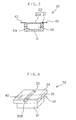
- Fig. 3 is a sectional view illustrating the construction of a safety device 131 according to a first embodiment of the present invention.
- the safety device 131 can be used instead of the safety device 130 in the secondary battery shown in Fig. 2.
- components corresponding those shown in Fig. 1 are denoted by the same reference numerals as in Fig. 1.
- the thin plate 20 having a very small thickness.
- the thin plate 20 is composed of a ceramic material, for example, the thickness thereof is about 0.1mm or smaller.
- Such a thin ceramic plate may be cracked even only by holding it with tweezers and, therefore, is difficult to handle in the fabrication process.
- a cover member 22 which has a thin plate portion 20A and a peripheral greater thickness portion 21 integrally formed with the thin plate portion 20A. More specifically, the safety device 131 is constructed such that a container 10 having a recess 10a in the center thereof is covered with the cover member 22 to define a sealed reference pressure chamber 50 therein.
- the cover member 22 is free from cracking in the fabrication process, because the cover member 22 can be handled by holding the greater thickness portion 21 thereof.
- the pressure difference between opposite sides of the thin plate portion 20A of the cover member 22 is assuredly ruptured.
- the safety device 131 is highly reliable as in the first arrangement.
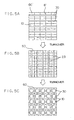
- Fig. 4 is a perspective view illustrating the construction of a safety device 132 according to a second embodiment of the present invention.
- the safety device 132 can be employed instead of the safety device 130 in the secondary battery shown in Fig. 2.
- components corresponding those shown in Fig. 1 are denoted by the same reference numerals as in Fig. 1.
- the safety device 132 is constructed such that the mouth of a container 10 having a recess 10a is covered with a substrate 24 which has a greater thickness than the thin plate 20 to define a reference pressure chamber 50 therein.
- a groove having a flat bottom face is provided in a surface of the substrate 24 opposite from the reference pressure chamber 50, and a portion of the substrate 24 under the groove serves as a thin plate portion 20B.
- the thickness of the thin plate portion 20B can accurately be set by properly selecting a working method.
- the thin plate portion 20B is adapted to be ruptured when a pressure difference between opposite sides thereof reaches a predetermined level.
- a conductive path 30 is formed on a surface of the thin plate portion 20B facing to the reference pressure chamber (or opposite from the groove 23), and adapted to be cut off when the thin plate portion 20B is ruptured.
- the substrate 24 has a rectangular configuration of a size slightly greater than the container 10 as viewed in plan.
- the electrodes 40, 40 are brazed to the conductive path 30 on portions of the substrate 24 projecting outside the container 10.
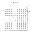
- Figs. 5A, 5B and 5C are diagrams schematically illustrating a fabrication process for the safety device 132 of this embodiment.
- a substrate 60 having split grooves 61 formed in one surface thereof is prepared which is to be split along the grooves 61 into a plurality of substrate pieces.
- the thickness of the substrate 60 is greater than the thickness of the thin plate portion 20B which is adapted to be ruptured for cut-off of the conductive path 30.
- a plurality of conductive paths 30 for a plurality of safety devices 132 are formed on the substrate 60 by a printing process or the like (Fig. 5A).
- the substrate 60 is turned over, and a plurality of grooves 23 are formed on the other surface of the substrate 60 as extending perpendicularly to the conductive paths 30 by a laser machining process or a sand-blast process for formation of thin plate portions 20B (Fig. 5B).
- the substrate 60 is turned over again, and a plurality of containers 10 each having a recess 10a in the center thereof are bonded onto the surface of the substrate 60 formed with the conductive paths 30 with an adhesive or the like (Fig. 5C). Thereafter, the substrate 60 is split along the split grooves 61 to provide the plurality of safety devices 132 each having the construction shown in Fig. 4.
- the printing process for the formation of the conductive paths 30 and the groove forming process for formation of the thin plate portions 20B can be performed in a batch for fabrication of the plurality of safety devices 132. Therefore, the safety devices 132 can efficiently be mass-produced.
- the electrode attaching step can also easily be adapted for the mass production.
- the substrate 60 shown in Fig. 5C is split into a plurality of elongate substrate strips extending along the conductive paths 30 in the substrate splitting process, and the electrodes 40 are attached to the conductive paths of each of the elongate substrate strips for plural safety devices. Then, the electrodes 40 and the substrate strips are further split. Accordingly, there is no need to handle the electrodes 40 on a one-by-one basis, thereby facilitating the fabrication process.
- the brazing process can effectively be performed, since the plurality of electrodes 40 can be brazed to the conductive paths at a time.
- a 0.3-mm thick alumina-based ceramic plate which was formed with split slits and relatively easy to handle was employed as the splittable substrate 60.
- Conductive portions 30 for a plurality of safety devices 132 were formed of Cu on one surface of the substrate 60 by a thick film printing process.
- Grooves 23 each having a width of about 1mm and a depth of 0.25mm were formed on the other surface of the substrate 60 as extending perpendicularly to the conductive portions 30 by a laser machining process.
- containers 10 separately prepared were bonded onto the surface of the substrate 60 not formed with the grooves 23 with an epoxy adhesive. Then, the substrate 60 was split along the split slits for provision of the individual devices. This fabrication process allowed for easy mass production of the very small size devices.
- Fig. 6A is a partially broken perspective view illustrating a safety device 133 of a third embodiment of the present invention.
- a spacer plate 7 is provided integrally with a thin plate 5 on one surface thereof.
- the thin plate 5 is composed of a brittle material such as a ceramic material, a glass material or a glass ceramic material.
- the spacer plate 7 is a hollow cylindrical member which has a hollow central portion serving as a reference pressure chamber 6 and is connected to the peripheral edge of the thin plate 5.
- a cover plate 9 is provided integrally with the spacer plate 7 on a side thereof opposite from the thin plate 5 as covering the reference pressure chamber 6.
- the cover plate 9 is formed with a through-hole 9a, which is closed with a filler 8.
- a conductive path 10 is formed on the other surface (exposed surface) of the thin plate 5 by a vapor deposition process.
- the safety device 133 can be employed instead of the safety device 130 in the secondary battery shown in Fig. 2.
- a greater pressure is exerted on the surface of the thin plate 5 opposite from the reference pressure chamber 6 due to overcharging or the like so that a pressure difference between the opposite sides of the thin plate 5 reaches an abnormal level greater than a predetermined level, the thin plate 5 is ruptured to cut off the conductive path 10 for interruption of the charging of the secondary battery from a main power source. Since the thin plate 5 is formed of a brittle material such as a ceramic material, a glass material or a glass ceramic material, the thin plate 5 can assuredly be ruptured without elastic deformation to cut off the conductive path 10.
- a juncture between the spacer plate 7 and the thin plate 5 has a corner A (inner corner facing to the reference pressure chamber 6) having a curvature radius R of not greater than 0.1mm, so that the thin plate 5 can assuredly be ruptured at an abnormal pressure.
- a curvature radius R of not greater than 0.1mm
- the juncture corner is not a round corner but a flat face corner as indicated in Fig. 6C
- the breadth C of a flat face is herein defined as the curvature radius. Such definition is applied to any other configuration of the juncture corner.
- the safety device 133 is fabricated by stacking green sheets one on another, so that the curvature radius R of the juncture corner A can be made not greater than 0.1mm.
- the reference pressure chamber 6 preferably has such a plan configuration that the major- to minor-axis length ratio thereof is in a range between 1.0 and 1.2.
- the conductive path 10 can instantaneously and completely be cut off when abnormal pressure occurs.
- the terms "major axis length” and “minor axis length” herein mean the greatest diameter and the smallest diameter, respectively, of the reference pressure chamber 6 as viewed in plan.
- the major axis length and the minor axis length are regarded as corresponding to the length of the diagonal thereof and the length of the side thereof, respectively. In such a case, the major- to minor-axis length ratio is about 1.4 and, hence, falls out of the preferred scope.
- the material for the thin plate 5 to be ruptured has a Young's modulus of not lower than 60GPa and a flexural strength of 70 to 1000MPa, and the thickness of the thin plate 5 is 10 to 100 ⁇ m.
- the spacer plate 7 and the cover plate 9 are preferably composed of the same material as the thin plate 5.
- a slurry is prepared by blending a powdery ceramic material such as alumina or zirconia, a powdery glass material or a powdery glass ceramic material with an organic binder, an plasticizer and a solvent.
- a thin green sheet 5' for preparation of the thin plate 5, a thick green sheet 7' for preparation of the spacer plate 7 and a green sheet 9' for preparation of the cover plate 9 as shown in Fig. 7 are formed from the resulting slurry by a doctor blade method, a calender roll method, a rolling method or a press method.
- a water-soluble slurry may be employed, instead of the solvent-based slurry, which is prepared by blending a powdery ceramic material with an organic binder, a plasticizer, a dispersant and deionized water.
- the thick sheet may otherwise be prepared by combining a plurality of thin green sheets into a laminate.
- the thick green sheet 7' is formed with a through-hole 6' which will later serve as the reference pressure chamber 6 and the green sheet 9' is formed with a minute through-hole 9a' by a stamping process using a metal stamping die.
- the thin green sheet 5', the thick green sheet 7' having the through-hole 6' and the thick green sheet 9' having the minute through-hole 9a' are stacked one on another to be combined into a laminate and, after a while, the resulting laminate is integrally sintered at a temperature of not lower than 800 C in an atmospheric environment.
- the spacer plate 7 and the cover plate 9 are thus integrally sintered, the conducive path 10 is formed on the thin plate 5. Then, the through-hole 9a extending to the reference pressure chamber 6 is closed with a filler 8 such as of a resin. Thus, the safety device 133 of the present embodiement is obtained.
- the through-hole 9a which is finally closed with the filler 8 serves to keep the reference pressure chamber 6 at an atmospheric pressure for prevention of breakage of the laminate during the fabrication process.
- a powdery ceramic material such as alumina or zirconia, a glass material or a glass ceramic material is mixed with a binder, and green sheets for the spacer plate 7 and the thin plate 5 are formed from the resulting mixture by a press method.
- the sheets are stacked one on the other to be combined into a laminate, and integrally sintered at a temperature of not lower than 800 C in an atmospheric environment.
- the reference pressure chamber 6 is covered with the cover plate 9 and, after the thin plate 5 is processed to a desired thickness, the conductive path 10 is formed on the thin plate 5.
- the conductive path 10 is formed of a metal such as Cu, Ni, Al, Au, Ag or Pd or an alloy thereof by a plating method, a sputtering method, a vapor deposition method or a printing method.
- the safety device 133 has a very small size, so that a multiplicity of such safety devices can be produced at a time by a multi-production method.
- a multiplicity of through-holes 6' are formed in a single green sheet 7', which is then combined into a laminate with a green sheet 9' formed with a multiplicity of through-holes 9a' and a thin green sheet 5'. Then, the laminate is sintered. After formation of conduction paths 10, the resulting product is cut.
- the multiplicity of safety devices 133 are produced at a time.
- the curvature radius R of the corner A of the juncture between the thin plate 5 and the spacer plate 7 can be reduced to not greater than 0.1mm by integrally sintering at least the green sheets for the thin plate 5 and the spacer plate 7 combined into a laminate. This allows for assured rupture of the thin plate 5 under an abnormal pressure.
- the safety device of this embodiment is constructed such that the cover plate 9 is proviced on one side of the thin plate 5 to define the sealed reference pressure chamber 6, the safety device may include only the thin plate 5 and the spacer plate 7 and be designed so that the thin plate 5 is ruptured by a pressure difference between the opposite sides of the thin plate 5 in another embodiment.
- the alumina power was blended with an acrylic-ester-based binder, a plasticizer of hexylene glycol, a dispersant and deionized water for preparation of a water-soluble slurry.
- a thin alumina green sheet and thick alumina green sheets were prepared from the slurry by the calender roll method.
- the thick sheets were respectively stamped out with metal dies for formation of a through-hole 6' which will later serve as the reference pressure chamber 6 and a minute through-hole 9a' in the respective sheets.
- the metal dies herein used were configured so as to allow the through-holes 6' and 9' to have desired shapes after the sintering.
- the metal die for the stamping of the minute through-hole 9a' has a diameter of 0.3mm.
- the thin green sheet 5', the green sheet 7' having the through-hole 6' and the green sheet 9' having the minute through-hole 9a' were stacked one on another as shown in Fig. 7 to be combined into a laminate.
- the resulting laminate was thermocompress-bonded at 60 C and 50kgf/cm 2 , and then sintered at 1570 C in an atmospheric environment.
- the safety device 133 was obtained.
- safety device samples were each fabricated by integrally press-molding a spacer plate portion and a thin plate portion with a mold by a known press molding method and then subjecting the thin plate portion to a thickness adjustment process.
- the molds used herein were designed so as to have different corner configurations which each corresponded to an inner corner of the juncture between the spacer plate portion and the thin plate portion.
- safety device samples which had inner corners having different curvature radii R within a range between 0.01 to 0.20mm at the juncture between the spacer plate 7 and the thin plate 5 were fabricated, and a relationship between the curvature radius of the juncture corner and the thin plate rupture ratio was examined.
- the thin plates 5 of the safety device smaples each had a thickness of 50 ⁇ m.
- the thin plate rupture ratio was determined in the following manner.
- the fabricated safety device samples were put in a pressure vessel, and the inside pressure of the vessel was gradually increased.
- the rupture ratio was calculated on the basis of the number of safety device samples in which the thin plate was ruptured until the pressure reached a maximum pressure of 7kg/cm 2 .
- the maximum pressure was set to a level corresponding to an inside pressure level of a secondary battery which was considered to be abnormal.
- the safety device samples A-4, A-5 in which the curvature radius R of the corner of the juncture between the spacer plate 7 and the thin plate 5 was greater than 0.1mm were fabricated by the press molding method, and had lower levels of rupture ratio, i.e., not higher than 60%.
- the other safety device samples which were fabricated by the green sheet stacking method each had a curvature radius R of not greater than 0.1mm with a higher rupture ratio, i.e., not lower than 70%.
- the curvature radius of the juncture corner of the safety device should be 0.1mm or smaller, preferably as small as possible. It is also understood that the safety device fabrication process using green sheets is more advantageous.
- a major- to minor-axis length ratio of not higher than 1.2 (samples A-1 to A-3, B-1, B-2, and D-1 to D-2) provided for a rupture ratio of 100%. Even where the reference pressure chamber had any other configuration, the rupture ratio was not influenced by the configuration, as long as the major- to minor-axis length ratio of the juncture corner is within the aforesaid range.
- Safety device samples having substantially the same construction as the safety device 133 were each fabricated in substantially the same manner as described above by stacking green sheets composed of a powdery ceramic material (alumina or zirconia), a glass material or a glass ceramic material as shown by A to F in Table 3.
- the sintering temperature was properly selected depending on the type of the material.
- Material Characteristics of material Young's modulus(GPa) Flexural strength(MPa) A Alumina 325 300 B Zirconia 180 1000 C Zirconia 200 1500 D Glass ceramic 100 200 E Glass 58 70 F Crystallized Glass 100 240
- the safety device samples were each constructed such that: the thin plate 5 thereof had a thickness of 8 to 150pm; the reference pressure chamber 6 was of a circular configuration having a diameter of 3mm and a major- to minor-axis length ratio of 1.0; and the through-hole 9a communicating with the reference pressure chamber 6 had a diameter of 0.3mm and was closed with a resin.
- the safety device samples thus fabricated were put in a pressure vessel, and the inside pressure of the vessel was gradually increased to a maximum pressure of 7kg/cm 2 for determination of the thin plate rupture ratio.
- the maximum pressure was set to a level corresponding to an inside pressure level of a secondary battery which was considered to be abnormal.
- the material for the thin plate 5 has a Young's modulus of not lower than 60GPa and a flexural strength of 80 to 1000MPa. This is applicable to the thin plate 20 and the thin plate portions 20A and 20B according to the first to third embodiments.
- the thin plate 5 had a thickness of smaller than 10 ⁇ m
- the thin plate was liable to have minute defects therein because of its smaller thickness. Accordingly, there was air communication between the inside and outside of the reference pressure chamber 6, making it impossible to rupture the thin plate 5 or resulting in a lower rupture ratio.
- a greater thickness of the thin plate resulted in a lower rupture rate because a higher pressure was required for the rupture of the thin plate.
- the thickness of the thin plate 5 is 10 to 100 ⁇ m. This is applicable to the thin plate 20 of the first arrangement. It is more preferred that the thickness of the thin plate 5 for the safety device is 25 to 75 ⁇ m. This is applicable to the thin plate 20 and the thin plate portions 20A and 20B according to the first arrangement and first two embodiments.
- the thin plates 20, 5 and the substrate 60 may be composed of any brittle material selected from ceramic materials such as alumina-, zirconia- and titania-based ceramic materials, forsterite, steatite and cordierite, various glass materials, and glass-ceramic composite materials.
- the conductive paths 30, 10 may be composed of any metal selected from Cu, Ni, Al, Au, Ag and stainless steel or an alloy of any of these metals.
- a single safety device is incorporated in the casing of the secondary battery in the embodiments described above, two or more safety devices may be connected in series and interposed between the internal and external electrodes. In such a case, effectuation of any of these safety devices interrupts the charging process of the battery. Thus, the reliability of the secondary battery can further be improved.
- the safety device of the present invention can be used as an explosion-preventive safety device for preventing an explosion due to pressure buildup for use not only in the secondary battery but also in any of various apparatuses such as air compressors. That is, the safety device of the present invention is applicable to various pressure-responsive safety devices which can be effectuated at a desired pressure level by properly selecting the thickness of the thin plate.
Landscapes
- Chemical & Material Sciences (AREA)
- Chemical Kinetics & Catalysis (AREA)
- Electrochemistry (AREA)
- General Chemical & Material Sciences (AREA)
- Physics & Mathematics (AREA)
- General Physics & Mathematics (AREA)
- Fluid Mechanics (AREA)
- Connection Of Batteries Or Terminals (AREA)
- Gas Exhaust Devices For Batteries (AREA)
Claims (12)
- Dispositif de sécurité comprenant :où une surface de la plaque mince (5) est présente dans une chambre de pression de référence (6) qui est partiellement formée par le trou traversant (6).une plaque mince (5) en matériau friable adaptée de façon à se rompre en raison d'une différence entre les pressions s'exerçant sur les côtés opposés de celle-ci ; etun trajet conducteur (30, 10) prévu sur la plaque mince (5) et adapté de façon à être coupé par la rupture de la plaque mince (5) ; etune plaque d'espacement (7) qui est montée de façon intégrante à la plaque mince (5) sur une surface de celle-ci et possédant un trou traversant (6) à travers lequel une partie de cette une surface de la plaque mince (7) est exposée ;
- Dispositif de sécurité, selon la revendication 1, dans lequel la chambre de pression de référence (6) est scellée.
- Dispositif de sécurité, selon la revendication 1 ou la revendication 2, dans lequel une jointure (A) entre la plaque d'espacement (7) et la plaque mince (5) possède un angle interne ayant un rayon de courbure qui n'est pas supérieur à 0,1 mm.
- Dispositif de sécurité, selon l'une quelconque des revendications 1 à 3, dans lequel une plaque de couverture (9) est prévue sur l'un des côtés de la plaque d'espacement (7) en face de la plaque mince (5) afin de couvrir le côté en vue de définir une chambre de pression de référence (6).
- Dispositif de sécurité, selon l'une quelconque des revendications 1 à 4, dans lequel la chambre de pression de référence (6) a un rapport de longueur grand axe/petit axe de 1,0 à 1,2 quand on le voit en plan.
- Dispositif de sécurité, selon l'une quelconque des revendications 1 à 5, dans lequel le matériau friable est sélectionné à partir du groupe constitué de matériaux en céramique, de matériaux en verre et de matériaux en vitrocéramique.
- Dispositif de sécurité, selon l'une quelconque des revendications 1 à 6, dans lequel le matériau friable a un module de Young qui n'est pas inférieur à 60 GPa et une résistance à la flexion de 80 à 1000 MPa.
- Dispositif de sécurité, selon l'une quelconque des revendications 1 à 7, dans lequel la plaque mince (5) a une épaisseur de 10 à 100 µm.
- Batterie secondaire qui comporte un carter (110), une solution électrolytique (70), une pluralité d'électrodes internes (90, 100) qui sont immergées dans la solution électrolytique (70) à l'intérieur du carter (110), et une électrode externe (120) qui est connectée à l'une des électrodes internes (90, 100), la batterie secondaire comprenant un dispositif de sécurité (133), selon l'une quelconque des revendications 1 à 8, le dispositif de sécurité (133) étant connecté entre cette une électrode interne (90) et l'électrode externe (120).
- Procédé de fabrication d'un dispositif de sécurité, selon l'une quelconque des revendications 1 à 8, comprenant les étapes suivantes :formation d'une feuille verte pour la plaque mince à partir d'un matériau friable ;formation d'une feuille verte pour la plaque d'espacement possédant le trou traversant qui ultérieurement va faire partie de la chambre de pression de référence ;stratification des feuilles vertes pour la plaque mince et la plaque d'espacement pour obtenir un stratifié ;frittage intégral du stratifié ; etformation du trajet conducteur (10) sur l'autre surface de la plaque mince (5).
- Procédé, selon la revendication 10, comprenant en outre l'étape consistant à former une feuille verte pour une plaque de couverture, où l'étape de stratification inclut la stratification des feuilles vertes pour la plaque d'espacement, la plaque mince et la plaque de couverture alors que la feuille verte pour la plaque d'espacement est maintenue entre celles-ci.
- Procédé, selon la revendication 11, comprenant en outre les étapes consistant à former un trou traversant dans une partie de la plaque de couverture qui s'oppose à la chambre de pression de référence et, après l'étape de frittage, la fermeture du trou traversant afin de sceller la chambre de pression de référence.
Applications Claiming Priority (4)
| Application Number | Priority Date | Filing Date | Title |
|---|---|---|---|
| JP11975698 | 1998-04-28 | ||
| JP10119756A JPH11312515A (ja) | 1998-04-28 | 1998-04-28 | 安全装置及びこれを用いた二次電池 |
| JP33722698 | 1998-11-27 | ||
| JP10337226A JP2000164203A (ja) | 1998-11-27 | 1998-11-27 | 安全装置とその製造方法、及びそれを用いた二次電池 |
Publications (2)
| Publication Number | Publication Date |
|---|---|
| EP0954040A1 EP0954040A1 (fr) | 1999-11-03 |
| EP0954040B1 true EP0954040B1 (fr) | 2004-06-16 |
Family
ID=26457430
Family Applications (1)
| Application Number | Title | Priority Date | Filing Date |
|---|---|---|---|
| EP99303274A Expired - Lifetime EP0954040B1 (fr) | 1998-04-28 | 1999-04-27 | Dispositif de sécurité et batterie secondaire utilisant un tel dispositif |
Country Status (3)
| Country | Link |
|---|---|
| US (1) | US6335109B1 (fr) |
| EP (1) | EP0954040B1 (fr) |
| DE (1) | DE69917987T2 (fr) |
Families Citing this family (5)
| Publication number | Priority date | Publication date | Assignee | Title |
|---|---|---|---|---|
| JP3698925B2 (ja) * | 1999-08-23 | 2005-09-21 | アルプス電気株式会社 | 電池用感圧ブレーカー |
| US6602633B1 (en) * | 1999-09-13 | 2003-08-05 | Hosiden Corporation | Crush type pressure detecting device, rechargeable battery with pressure detecting device, and portable electronic device |
| JP2001216954A (ja) * | 2000-01-31 | 2001-08-10 | Alps Electric Co Ltd | 感圧電流遮断機構を有する電池 |
| DE102011018866A1 (de) * | 2010-12-17 | 2012-06-21 | Ads-Tec Gmbh | Akkublock mit einer Trennvorrichtung |
| DE102022115840A1 (de) | 2022-06-24 | 2024-01-04 | Volkswagen Aktiengesellschaft | Batterie mit geschwächter Verbindung von Gehäusemantel und Gehäusedeckel |
Family Cites Families (12)
| Publication number | Priority date | Publication date | Assignee | Title |
|---|---|---|---|---|
| GB1223576A (en) | 1968-10-18 | 1971-02-24 | Steelweld Ltd | Improvements in and relating to friction welding |
| DE2436443C3 (de) | 1974-07-29 | 1985-08-29 | Standard Elektrik Lorenz Ag, 7000 Stuttgart | Explosionssicherer elektrischer Kondensator |
| DE3151469A1 (de) | 1981-12-24 | 1983-07-07 | Diehl GmbH & Co, 8500 Nürnberg | "aufladbare elektrische zelle" |
| GB2174544B (en) | 1985-05-01 | 1988-08-24 | Ric Limited | Improvements in capacitous employing protective devices |
| JPH07105932A (ja) | 1993-10-08 | 1995-04-21 | Sony Corp | 感圧電流遮断素子及び密閉型電池 |
| EP0674351B1 (fr) * | 1994-03-03 | 2002-08-14 | Japan Storage Battery Company Limited | Dispositif de sécurité pour batterie |
| DE4411289A1 (de) | 1994-03-31 | 1995-10-05 | Varta Batterie | Mehrzellige Akkumulatorenbatterie |
| JP3249883B2 (ja) | 1994-06-13 | 2002-01-21 | アルプス電気株式会社 | 電流路遮断機能付き電池 |
| US6120928A (en) * | 1994-07-07 | 2000-09-19 | Alps Electric Co., Ltd. | Protection device and battery cell using this protection device |
| JP3306257B2 (ja) | 1995-08-11 | 2002-07-24 | アルプス電気株式会社 | 2次電池の安全装置 |
| JPH09329507A (ja) | 1996-06-12 | 1997-12-22 | Alps Electric Co Ltd | 圧力遮断センサ |
| JPH1023657A (ja) | 1996-07-03 | 1998-01-23 | Makoto Yamamoto | 進相コンデンサの異常検出装置 |
-
1999
- 1999-04-27 DE DE69917987T patent/DE69917987T2/de not_active Expired - Fee Related
- 1999-04-27 US US09/299,583 patent/US6335109B1/en not_active Expired - Fee Related
- 1999-04-27 EP EP99303274A patent/EP0954040B1/fr not_active Expired - Lifetime
Also Published As
| Publication number | Publication date |
|---|---|
| DE69917987T2 (de) | 2005-06-23 |
| US6335109B1 (en) | 2002-01-01 |
| EP0954040A1 (fr) | 1999-11-03 |
| DE69917987D1 (de) | 2004-07-22 |
Similar Documents
| Publication | Publication Date | Title |
|---|---|---|
| EP3723154B1 (fr) | Plaque de pressage supérieure, batterie secondaire et procédé de fabrication de batterie secondaire | |
| CN109980149B (zh) | 用于储能装置的防爆外壳以及储能装置 | |
| JP7353383B2 (ja) | エネルギー貯蔵装置用防爆ケーシング及びエネルギー貯蔵装置 | |
| KR100602504B1 (ko) | 밀폐형 전지 및 밀봉체 | |
| CN100448068C (zh) | 用于二次电池的二次保护元件 | |
| JPH05314959A (ja) | 電池の安全弁装置 | |
| CN220358209U (zh) | 电池 | |
| US6335109B1 (en) | Safety device and secondary battery using the same | |
| EP0158703A1 (fr) | Elément galvanique fermé hermétiquement muni d'un dispositif de ventilation de sécurité | |
| US6900616B2 (en) | Current interrupt device for rechargeable cells | |
| JP7785965B2 (ja) | 電池用パッケージおよび電池モジュール | |
| KR100517371B1 (ko) | 밀폐형 전지 | |
| JPH0513054A (ja) | 密閉式角型蓄電池とその製造方法 | |
| KR101130097B1 (ko) | 안전장치를 구비한 전기 에너지 저장장치 | |
| KR100502787B1 (ko) | 밀폐형 전지 및 밀봉체 | |
| KR100501846B1 (ko) | 밀폐형 전지 및 밀봉체 | |
| JP2000164203A (ja) | 安全装置とその製造方法、及びそれを用いた二次電池 | |
| KR100855181B1 (ko) | 이중 접속 구조의 원통형 이차전지 | |
| US11251480B2 (en) | Miniature electrochemical cell having a casing of a conductive plate closing an open-ended ceramic container having two via holes supporting opposite polarity platinum-containing conductive pathways | |
| JP2001176496A (ja) | 安全装置 | |
| JPH11312515A (ja) | 安全装置及びこれを用いた二次電池 | |
| JP3254261B2 (ja) | 電池用ラプチャーの製造方法 | |
| EP4738587A1 (fr) | Batterie secondaire et module de batterie la comprenant | |
| JP3213635B2 (ja) | 円筒形リチウムイオン二次電池 | |
| JP2002015723A (ja) | 安全装置 |
Legal Events
| Date | Code | Title | Description |
|---|---|---|---|
| PUAI | Public reference made under article 153(3) epc to a published international application that has entered the european phase |
Free format text: ORIGINAL CODE: 0009012 |
|
| AK | Designated contracting states |
Kind code of ref document: A1 Designated state(s): DE FI GB NL |
|
| AX | Request for extension of the european patent |
Free format text: AL;LT;LV;MK;RO;SI |
|
| 17P | Request for examination filed |
Effective date: 20000331 |
|
| AKX | Designation fees paid |
Free format text: DE FI GB NL |
|
| 17Q | First examination report despatched |
Effective date: 20020606 |
|
| GRAP | Despatch of communication of intention to grant a patent |
Free format text: ORIGINAL CODE: EPIDOSNIGR1 |
|
| GRAS | Grant fee paid |
Free format text: ORIGINAL CODE: EPIDOSNIGR3 |
|
| GRAA | (expected) grant |
Free format text: ORIGINAL CODE: 0009210 |
|
| AK | Designated contracting states |
Kind code of ref document: B1 Designated state(s): DE FI GB NL |
|
| REG | Reference to a national code |
Ref country code: GB Ref legal event code: FG4D |
|
| REF | Corresponds to: |
Ref document number: 69917987 Country of ref document: DE Date of ref document: 20040722 Kind code of ref document: P |
|
| PLBE | No opposition filed within time limit |
Free format text: ORIGINAL CODE: 0009261 |
|
| STAA | Information on the status of an ep patent application or granted ep patent |
Free format text: STATUS: NO OPPOSITION FILED WITHIN TIME LIMIT |
|
| 26N | No opposition filed |
Effective date: 20050317 |
|
| PGFP | Annual fee paid to national office [announced via postgrant information from national office to epo] |
Ref country code: NL Payment date: 20060403 Year of fee payment: 8 |
|
| NLV4 | Nl: lapsed or anulled due to non-payment of the annual fee |
Effective date: 20071101 |
|
| PG25 | Lapsed in a contracting state [announced via postgrant information from national office to epo] |
Ref country code: NL Free format text: LAPSE BECAUSE OF NON-PAYMENT OF DUE FEES Effective date: 20071101 |
|
| PGFP | Annual fee paid to national office [announced via postgrant information from national office to epo] |
Ref country code: DE Payment date: 20080502 Year of fee payment: 10 |
|
| PGFP | Annual fee paid to national office [announced via postgrant information from national office to epo] |
Ref country code: FI Payment date: 20080411 Year of fee payment: 10 |
|
| PGFP | Annual fee paid to national office [announced via postgrant information from national office to epo] |
Ref country code: GB Payment date: 20080430 Year of fee payment: 10 |
|
| GBPC | Gb: european patent ceased through non-payment of renewal fee |
Effective date: 20090427 |
|
| PG25 | Lapsed in a contracting state [announced via postgrant information from national office to epo] |
Ref country code: FI Free format text: LAPSE BECAUSE OF NON-PAYMENT OF DUE FEES Effective date: 20090427 Ref country code: DE Free format text: LAPSE BECAUSE OF NON-PAYMENT OF DUE FEES Effective date: 20091103 |
|
| PG25 | Lapsed in a contracting state [announced via postgrant information from national office to epo] |
Ref country code: GB Free format text: LAPSE BECAUSE OF NON-PAYMENT OF DUE FEES Effective date: 20090427 |