EP0954065A2 - Dispositif de connexion et appareil de transfert de données - Google Patents
Dispositif de connexion et appareil de transfert de données Download PDFInfo
- Publication number
- EP0954065A2 EP0954065A2 EP99302824A EP99302824A EP0954065A2 EP 0954065 A2 EP0954065 A2 EP 0954065A2 EP 99302824 A EP99302824 A EP 99302824A EP 99302824 A EP99302824 A EP 99302824A EP 0954065 A2 EP0954065 A2 EP 0954065A2
- Authority
- EP
- European Patent Office
- Prior art keywords
- data transfer
- signal cable
- receptacle
- switch
- transfer speed
- Prior art date
- Legal status (The legal status is an assumption and is not a legal conclusion. Google has not performed a legal analysis and makes no representation as to the accuracy of the status listed.)
- Withdrawn
Links
- 238000012546 transfer Methods 0.000 title claims description 89
- 238000012545 processing Methods 0.000 claims description 28
- 238000003780 insertion Methods 0.000 claims description 15
- 230000037431 insertion Effects 0.000 claims description 15
- 230000003287 optical effect Effects 0.000 claims description 7
- 230000006698 induction Effects 0.000 claims description 4
- 238000010586 diagram Methods 0.000 description 5
- 238000000034 method Methods 0.000 description 5
- 238000010276 construction Methods 0.000 description 3
- 238000004891 communication Methods 0.000 description 2
- 238000001514 detection method Methods 0.000 description 2
- 230000005674 electromagnetic induction Effects 0.000 description 2
- 235000014676 Phragmites communis Nutrition 0.000 description 1
- 238000012790 confirmation Methods 0.000 description 1
- 238000007796 conventional method Methods 0.000 description 1
- 238000010291 electrical method Methods 0.000 description 1
- 230000009931 harmful effect Effects 0.000 description 1
- 239000002184 metal Substances 0.000 description 1
- 238000000465 moulding Methods 0.000 description 1
- 239000011347 resin Substances 0.000 description 1
- 229920005989 resin Polymers 0.000 description 1
Images


Classifications
-
- H—ELECTRICITY
- H01—ELECTRIC ELEMENTS
- H01R—ELECTRICALLY-CONDUCTIVE CONNECTIONS; STRUCTURAL ASSOCIATIONS OF A PLURALITY OF MUTUALLY-INSULATED ELECTRICAL CONNECTING ELEMENTS; COUPLING DEVICES; CURRENT COLLECTORS
- H01R13/00—Details of coupling devices of the kinds covered by groups H01R12/70 or H01R24/00 - H01R33/00
- H01R13/64—Means for preventing incorrect coupling
-
- H—ELECTRICITY
- H01—ELECTRIC ELEMENTS
- H01R—ELECTRICALLY-CONDUCTIVE CONNECTIONS; STRUCTURAL ASSOCIATIONS OF A PLURALITY OF MUTUALLY-INSULATED ELECTRICAL CONNECTING ELEMENTS; COUPLING DEVICES; CURRENT COLLECTORS
- H01R24/00—Two-part coupling devices, or either of their cooperating parts, characterised by their overall structure
- H01R24/28—Coupling parts carrying pins, blades or analogous contacts and secured only to wire or cable
-
- H—ELECTRICITY
- H01—ELECTRIC ELEMENTS
- H01R—ELECTRICALLY-CONDUCTIVE CONNECTIONS; STRUCTURAL ASSOCIATIONS OF A PLURALITY OF MUTUALLY-INSULATED ELECTRICAL CONNECTING ELEMENTS; COUPLING DEVICES; CURRENT COLLECTORS
- H01R2107/00—Four or more poles
Definitions
- the present invention relates to a connector device with a cable and a data transfer apparatus such as an electronic device which is connected by the connector device.
- a first data transfer apparatus 100 and a second data transfer apparatus 101 or other data transfer apparatuses (not shown) to be connected are connected via a signal cable 104 with plugs 103 which are inserted into receptacles 102 of respective apparatuses, and data is transferred via the signal cable 104.
- the invention has been achieved in consideration of the circumstances and its first object is to provide a connector device which can dissolve the harmful effects as mentioned above.
- the first object is achieved by a connector device comprising: a receptacle provided on a device (for example, a data transfer apparatus which will be described hereinlater) side; a plug which is connected at an end of a signal cable and inserted into the receptacle; and cable discriminating means (such as a switch group which will be described hereinlater) which is provided on the device side and discriminates the kind of the signal cable to be connected (such as maximum data transfer speed which will be described hereinlater).
- a connector device comprising: a receptacle provided on a device (for example, a data transfer apparatus which will be described hereinlater) side; a plug which is connected at an end of a signal cable and inserted into the receptacle; and cable discriminating means (such as a switch group which will be described hereinlater) which is provided on the device side and discriminates the kind of the signal cable to be connected (such as maximum data transfer speed which will be described hereinlater).
- a data transfer apparatus comprising: a first data processing system (for example, a first data transfer apparatus which will be described hereinlater); a second data processing system (for example, a second data transfer apparatus which will be described hereinlater); a signal cable connecting the first and second data processing systems, through which data is transferred between the data processing systems; comparing means (for example, a CPU which will be described hereinlater) for comparing maximum data transfer speed information (A) of the first data processing system, maximum data transfer speed information (B) of the second data processing system, and maximum data transfer speed information (C) of the signal cable to be used; and transfer speed setting means (comprised of a CPU, a data transfer speed adjusting unit, and the like which will be described hereinlater) for selecting the lowest data transfer speed among the speed information (A), (B), and (C) as a comparison result and setting the lowest data transfer speed as an execution transfer speed, wherein data transfer is executed between the first data processing system and the second data processing system via
- the first invention has a construction as described above. Since the kind of the connected signal cable can be automatically known by the cable discriminating means, the device side can correspond to the kind. Consequently, the trouble such as confusion with the signal cables is dissolved and the quality, performance, and function of the whole system can be improved.
- the second invention has also a construction as described above. Since a reasonable execution transfer speed can be set from the maximum data transfer speed information of the data processing systems to be connected and the signal cable used for connection, data transfer is efficiently performed and the quality, performance, and function of the whole system can be improved.
- Fig. 1 is a perspective view of a plug of cable type 1 according to an embodiment of the invention.
- Fig. 2 is a perspective view of a plug of cable type 2 according to an embodiment of the invention.
- Fig. 3 is a perspective view of a plug of cable type 3 according to an embodiment of the invention.
- Fig. 4 is a perspective view of a plug of cable type 4 according to an embodiment of the invention.
- Fig. 5 is a perspective view of a plug of cable type 5 according to an embodiment of the invention.
- Fig. 6 is a perspective view of a receptacle according to a first embodiment of the invention.
- Fig. 7 is a partly enlarged cross section showing a state in which a plug is inserted into a receptacle.
- Fig. 8 is a functional block diagram of a data transfer apparatus according to an embodiment of the invention.
- Fig. 9 is a flowchart showing a data transfer processing routine according to an embodiment of the invention.
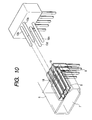
- Fig. 10 is an exploded perspective view of a receptacle and a switch according to a second embodiment of the invention.
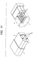
- Fig. 11 is a perspective view of a plug and a receptacle for explaining a third embodiment of the invention.
- Fig. 12 is a perspective view of a plug and a receptacle for explaining a fourth embodiment of the invention.
- Fig. 13 is a perspective view of a plug and a receptacle for explaining a fifth embodiment of the invention.
- Fig. 14 is an explanatory diagram showing an example of a connection state of data transfer apparatuses.
- Figs. 1 to 5 are perspective views of various plugs according to embodiments of the invention.
- Fig. 6 is a perspective view of a receptacle according to a first embodiment to which each of the plugs can be inserted.
- Fig. 7 is a partly enlarged cross section showing a state where the plug is inserted into the receptacle.
- a plug 2 is connected to a signal cable 1 (la to le) and an insertion engagement part 3 made by a resin molding is provided at an end of the plug 2.
- the insertion engagement part 3 has a shape which is asymmetrical laterally or vertically to prevent erroneous insertion.
- An opening 4 is formed in the center of the insertion engagement part 3 and a contact point (not shown) is provided in the opening 4.
- Fig. 1 shows a cable in which no recessed part 5 is formed in the insertion engagement part 3.
- Fig. 2 shows a cable in which one recessed part 5 is formed in the insertion engagement part 3.
- Fig. 3 shows a cable in which two recessed parts 5 are formed.
- Fig. 4 shows a cable in which three recessed parts 5 are formed.
- Fig. 5 shows a cable in which four recessed parts 5 are formed.
- Each of the recessed parts 5 is opened to the insertion end face of the plug 2.
- the signal cables la to le are classified as shown in Table 1 according to, for example, the maximum data transfer speed and have wire diameters adapted to the respective maximum data transfer speeds.
- Number of recessed part(s) 5 cable type maximum data transfer speed 0 1 400 Mbps 1 2 800 Mbps 2 3 1600 Mbps 3 4 3200 Mbps 4 5 6400 Mbps
- the maximum data transfer speeds become higher in accordance with the order of the cable types 1, 2, 3, and 4.
- armatures 8 which come into contact with the contact point of the plug 2 are provided in a housing 7 of a receptacle 6.
- a lead 9 is connected to each armature 8.
- the inside of the housing 7 has a shape which is asymmetrical laterally or vertically so as to be adapted to the outer shape of the plug 2.
- Two each of push-on type (or push-off type) switches 10 (10a to 10d) are provided on the upper and lower sides of the armature group 8. The switches 10a to 10d are disposed in the positions facing the recessed parts 5a to 5d of the plug 2, respectively.
- the kind of the signal cable that is, the maximum data transfer speed at which data can be transferred can be automatically discriminated in the embodiment.
- Fig. 8 is a functional block diagram of a data transfer apparatus.
- Fig. 9 is a flowchart showing a data transfer processing routine.
- a data transfer apparatus comprises: the receptacle 6 having therein the switches 10a to 10d; a decoder 11 for extracting a combination of the ON signals of the switches 10a to 10d as information; a CPU 12 for taking in various information, determining, processing, and the like; a storage unit 13 for storing decoding information of the switch 10 and a series of control programs, temporarily storing data, or the like; a signal processing unit 14 for processing signals which are inputted via the receptacle 6 so as to be easily dealt at the post stage and outputting the processed signals via the receptacle 6; a data processing unit 15 for processing information; a data transfer speed adjusting unit 16 for receiving a command of the CPU 12 and adjusting data transfer speeds of respective units; a bias voltage detecting unit 17 for detecting a bias voltage applied from the partner data transfer apparatus to be connected.
- the components have the connecting relation as shown in the diagram.
- the data transfer processing routine will be described with reference to Fig. 9.
- the example shows the routine from connection of an electronic device A serving as a first data transfer apparatus and an electronic device B serving as a second data transfer apparatus via a signal cable until starting of the transfer of signals.
- step (hereinbelow, abbreviated as "S") 1 each of the electronic devices A and B acquires the maximum data transfer speed of itself during initializing process after turn-on of the power.
- the predetermined lowest data transfer speed is a speed (for example, 100 Mbps) which is used in the present version and it is determined that all of the electronic devices can perform communication at this speed at the lowest.
- the key shape of the plug 2 inserted into the receptacle of the device that is, the presence or absence of the recessed part 5 and the position of the recessed part 5 is decoded by the decoder 11.
- the maximum data transfer speed of the signal cable 1 used for connection is calculated and temporarily stored in the storage unit 13.
- the maximum data transfer speed from the key shape of the plug 2 is calculated by referring to a preliminarily stored table in the storage unit 13.
- the maximum data transfer speeds of the self device, the partner device, and the signal cable 1 to be used are read from the storage unit 13 and compared by the CPU 12. The smallest value among them is found and set as an execution transfer speed to be used. For example, when it is assumed that the maximum data transfer speed (A) of the self device (electronic device A) is 3200 Mbps, the maximum data transfer speed (B) of the partner device (electronic device B) is 800 Mbps, and the maximum data transfer speed (C) of the signal cable is 1600 Mbps, the execution transfer speed to be used is set to the smallest value of 800 Mbps. The execution transfer speed is set by the CPU 12 and adjustment of the data transfer speeds of the respective units in association with the setting is carried out by the data transfer speed adjusting unit 16.
- the data transfer speed to be used is confirmed with the partner device.
- whether the confirmation is made or not is determined. If YES, the program determines the state as normal and enters a usual data transfer routine. If NO, the program enters an error processing routine.
- Fig. 10 is a perspective view of a receptacle and a switch group for explaining a second embodiment of the invention.
- the cable discriminating means for example, switch
- the receptacle 6 and the switch group 10 are separately provided.
- the switches 10 are inserted into four insertion holes 18 (only two of them are shown in the diagram) formed in the receptacle 6, and the switches 10 and the receptacle 6 become integral.
- a through hole or a projected part can be used.
- the number of the recessed parts, through holes, or projected parts indicative of the kind of the signal cable can be arbitrarily selected according to the number of kinds.
- Fig. 11 is a perspective view of a plug and a receptacle for explaining a third embodiment of the invention.
- magnets 20 are attached to the front end face of the insertion engagement part 3 of the plug 2 by proper means such as adhesion or embedding in accordance with the kind of the signal cable.
- magnetic induction switches 21 such as Hall devices or reed switches are attached to the receptacle 6 side. The arranging state of the magnets 20 is detected by the magnetic induction switches 21 to thereby discriminate the kind of the signal cable connected to the plugs 2.
- Fig. 12 is a perspective view of a plug and a receptacle for explaining a fourth embodiment of the invention.
- notches 22 are formed on the front end face of the insertion engagement part 3 of the plug 2 in accordance with the kind of the signal cable.
- optical sensors 23 each consisting of a light emitting device 23a and a light receiving device 23b are attached to the receptacle 6 side.
- the front end face of the insertion engagement part 3 comes close to the optical sensor 23 when the plug 2 is inserted into the receptacle 6.
- Light emitted from the light emitting device 23a is reflected by the front end face of the insertion engagement part 3 and a large amount of reflection light is received by the light receiving device 23b.
- the bottom face 24 of the notch 22 is away from the optical sensor 23 when the plug 2 is inserted into the receptacle 6.
- the reflection light of light emitted from the light emitting device 23a is received by the light receiving device 23b, the reflection light amount is small, so that the detection output of the light receiving device 23b is weak.
- the kind of the signal cable connected to the plug 2 is determined in accordance with the reflection light amount (detection output).
- Fig. 13 is a perspective view of a plug and a receptacle for explaining a fifth embodiment of the invention.
- short bars 25 such as metal thin plates are provided on the front end face of the insertion engagement part 3 of the plug 2 in accordance with the kind of the signal cable.
- a pair of electrodes 26 are attached at predetermined intervals to the receptacle 6 side.
- the pair of electrodes 26 come into contact with the electrically insulating plug 2 when the plug 2 is inserted into the receptacle 6, so that the electrodes 26 are not made conductive.
- the short bar 25 is provided, the pair of electrodes 26 come into contact with the short bar 25 and is electrically short-circuited when the plug 2 is inserted into the receptacle 6. Consequently, the kind of the signal cable connected to the plug 2 can be discriminated whether the electrodes 26 are short-circuited or not.
- the surface of the electrode 26 may be flat, by providing a projecting part on the surface of the electrode 26, the contact with the short bar 25 can be more secured.
- the invention is not limited to the foregoing embodiments.
- a bar code part, a different color part, an electromagnetic induction coil, or the like is provided on the plug side and optically or electromagnetically detected, thereby enabling the kind of the signal cable to be discriminated.
- the construction as mentioned above is provided and the kind of the connected signal cable can be automatically known by the cable discriminating means, so that the device side can correspond to the kind. Consequently, the trouble such as confusion with the signal cables is solved and the quality, performance, and function of the whole system can be improved.
- the detector can be moved when the plug is inserted.
- it is inserted by pushing all of detectors. Consequently, the detectors do not become hindrance and it is convenient that there is compatibility with an existing plug.
- the kind of the signal cable can be accurately discriminated so that the reliability can be improved.
- the data transfer can be efficiently performed as a result.
- the quality, performance, and function of the whole system can be improved.
Landscapes
- Details Of Connecting Devices For Male And Female Coupling (AREA)
Applications Claiming Priority (2)
| Application Number | Priority Date | Filing Date | Title |
|---|---|---|---|
| JP11703798 | 1998-04-27 | ||
| JP11703798 | 1998-04-27 |
Publications (2)
| Publication Number | Publication Date |
|---|---|
| EP0954065A2 true EP0954065A2 (fr) | 1999-11-03 |
| EP0954065A3 EP0954065A3 (fr) | 2001-04-04 |
Family
ID=14701883
Family Applications (1)
| Application Number | Title | Priority Date | Filing Date |
|---|---|---|---|
| EP99302824A Withdrawn EP0954065A3 (fr) | 1998-04-27 | 1999-04-12 | Dispositif de connexion et appareil de transfert de données |
Country Status (1)
| Country | Link |
|---|---|
| EP (1) | EP0954065A3 (fr) |
Cited By (2)
| Publication number | Priority date | Publication date | Assignee | Title |
|---|---|---|---|---|
| CN102288841A (zh) * | 2011-04-27 | 2011-12-21 | 株洲南车时代电气股份有限公司 | 一种通用测试接口的插件识别系统和方法 |
| US11264146B2 (en) | 2018-01-25 | 2022-03-01 | Lg Energy Solution, Ltd. | Flat cable with improved short-circuit prevention function |
Family Cites Families (2)
| Publication number | Priority date | Publication date | Assignee | Title |
|---|---|---|---|---|
| US5526350A (en) * | 1994-03-09 | 1996-06-11 | British Telecommunications Public Limited Company | Communication network with bandwidth managers for allocating bandwidth to different types of traffic |
| US5668419A (en) * | 1995-06-30 | 1997-09-16 | Canon Information Systems, Inc. | Reconfigurable connector |
-
1999
- 1999-04-12 EP EP99302824A patent/EP0954065A3/fr not_active Withdrawn
Cited By (3)
| Publication number | Priority date | Publication date | Assignee | Title |
|---|---|---|---|---|
| CN102288841A (zh) * | 2011-04-27 | 2011-12-21 | 株洲南车时代电气股份有限公司 | 一种通用测试接口的插件识别系统和方法 |
| CN102288841B (zh) * | 2011-04-27 | 2014-04-16 | 株洲南车时代电气股份有限公司 | 一种通用测试接口的插件识别系统和方法 |
| US11264146B2 (en) | 2018-01-25 | 2022-03-01 | Lg Energy Solution, Ltd. | Flat cable with improved short-circuit prevention function |
Also Published As
| Publication number | Publication date |
|---|---|
| EP0954065A3 (fr) | 2001-04-04 |
Similar Documents
| Publication | Publication Date | Title |
|---|---|---|
| US5222164A (en) | Electrically isolated optical connector identification system | |
| US5113467A (en) | Laser transmitter interlock | |
| CA2449527C (fr) | Repartiteur permettant l'interconnexion de lignes optiques de raccordement | |
| EP1271205B1 (fr) | Fiche de connecteur optique | |
| EP0595305B1 (fr) | Lecteur de cartes à circuits intégrés | |
| EP0790672A1 (fr) | Dispositif connecteur | |
| GB2327764A (en) | Measuring system with exchangeable sensors | |
| EP1041412A2 (fr) | Connecteur opto-électrique de type jack | |
| US7980767B2 (en) | Optical fiber connection system | |
| JP3001750B2 (ja) | プラグ・ジャック式光電共用伝送装置 | |
| EP0954065A2 (fr) | Dispositif de connexion et appareil de transfert de données | |
| WO2007129931A1 (fr) | Procédé, système et capteur de connexion servant à identifier le port d'un panneau de commutation | |
| US5447454A (en) | Connector | |
| JP2000021513A (ja) | コネクタ装置ならびにデータ転送装置 | |
| JPH08130058A (ja) | 電気コネクタ | |
| US20010016102A1 (en) | Plug part for a combined optical and electrical plug-and-socket connection | |
| US20220140546A1 (en) | Blind plug, data transmission system and method for indicating a power supply capability | |
| US5876238A (en) | Device and method for securing integrity of a blind autodock electrical connection | |
| EP0961984B1 (fr) | Connecteur de lecteurs de cartes | |
| JP2000340312A (ja) | 信号伝送装置及びプラグ | |
| JP2000180663A (ja) | 光コネクタおよび光コネクタ監視システム | |
| JP2600604B2 (ja) | ファイルスロット装置 | |
| KR100422060B1 (ko) | 패키지중계단자및이를구비한기록재생기기 | |
| JP2743059B2 (ja) | フィルム情報読取り装置 | |
| JP2001326033A (ja) | コネクタ接続方式 |
Legal Events
| Date | Code | Title | Description |
|---|---|---|---|
| PUAI | Public reference made under article 153(3) epc to a published international application that has entered the european phase |
Free format text: ORIGINAL CODE: 0009012 |
|
| AK | Designated contracting states |
Kind code of ref document: A2 Designated state(s): DE FR |
|
| AX | Request for extension of the european patent |
Free format text: AL;LT;LV;MK;RO;SI |
|
| PUAL | Search report despatched |
Free format text: ORIGINAL CODE: 0009013 |
|
| AK | Designated contracting states |
Kind code of ref document: A3 Designated state(s): AT BE CH CY DE DK ES FI FR GB GR IE IT LI LU MC NL PT SE |
|
| AX | Request for extension of the european patent |
Free format text: AL;LT;LV;MK;RO;SI |
|
| RIC1 | Information provided on ipc code assigned before grant |
Free format text: 7H 01R 23/02 A, 7H 01R 13/64 B, 7H 01R 29/00 B, 7H 01R 13/703 B |
|
| 17P | Request for examination filed |
Effective date: 20010414 |
|
| AKX | Designation fees paid |
Free format text: DE FR |
|
| 17Q | First examination report despatched |
Effective date: 20071214 |
|
| STAA | Information on the status of an ep patent application or granted ep patent |
Free format text: STATUS: THE APPLICATION IS DEEMED TO BE WITHDRAWN |
|
| 18D | Application deemed to be withdrawn |
Effective date: 20080425 |