EP0954145A2 - Démodulateur pour signaux MAQ ou MDP à deux détecteurs de phase - Google Patents
Démodulateur pour signaux MAQ ou MDP à deux détecteurs de phase Download PDFInfo
- Publication number
- EP0954145A2 EP0954145A2 EP99400967A EP99400967A EP0954145A2 EP 0954145 A2 EP0954145 A2 EP 0954145A2 EP 99400967 A EP99400967 A EP 99400967A EP 99400967 A EP99400967 A EP 99400967A EP 0954145 A2 EP0954145 A2 EP 0954145A2
- Authority
- EP
- European Patent Office
- Prior art keywords
- phase
- synchronizing signal
- detection
- synchronizing
- received
- Prior art date
- Legal status (The legal status is an assumption and is not a legal conclusion. Google has not performed a legal analysis and makes no representation as to the accuracy of the status listed.)
- Granted
Links
Images


Classifications
-
- H—ELECTRICITY
- H04—ELECTRIC COMMUNICATION TECHNIQUE
- H04L—TRANSMISSION OF DIGITAL INFORMATION, e.g. TELEGRAPHIC COMMUNICATION
- H04L27/00—Modulated-carrier systems
- H04L27/32—Carrier systems characterised by combinations of two or more of the types covered by groups H04L27/02, H04L27/10, H04L27/18 or H04L27/26
- H04L27/34—Amplitude- and phase-modulated carrier systems, e.g. quadrature-amplitude modulated carrier systems
- H04L27/38—Demodulator circuits; Receiver circuits
-
- H—ELECTRICITY
- H04—ELECTRIC COMMUNICATION TECHNIQUE
- H04L—TRANSMISSION OF DIGITAL INFORMATION, e.g. TELEGRAPHIC COMMUNICATION
- H04L27/00—Modulated-carrier systems
- H04L27/18—Phase-modulated carrier systems, i.e. using phase-shift keying
- H04L27/22—Demodulator circuits; Receiver circuits
Definitions
- the present invention generally relates to demodulating methods and receiver apparatuses, and more particularly to a demodulating method which demodulates a received signal received by a receiver apparatus by detecting an absolute phase of signal points, and a receiver apparatus which employs such a demodulating method.
- the communication is made by employing a digital modulation technique such as the BPSK, QPSK, nPSK and nQAM.
- a digital modulation technique such as the BPSK, QPSK, nPSK and nQAM.
- the signal modulated by the digital modulation technique is demodulated in a digital demodulator unit of a receiver apparatus, but in general, the detection of the absolute phase becomes uncertain at the time of the demodulation.
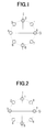
- FIGS. 1 and 2 respectively are diagrams for explaining the detection of the absolute phase when demodulating a signal which is demodulated by the 8PSK. If it is assumed that FIG. 1 shows the correct positions of data 1 through 8, a normal digital demodulator unit cannot judge such correct positions of the data 1 through 8, and can only judge the positions where the data should stop. For this reason, even if the positions where the data should stop are correct, the positions of the data 1 through 8 may deviate by 45 degrees from the correct positions as shown in FIG. 2, for example. In this case, with respect to the correct positions of the data 1 through 8 shown in FIG. 1, a total of 8 possible patterns could occur as the phase error, including the pattern shown in FIG. 2.
- the synchronizing signal is made up of several bits. This is because, if the number of bits forming the synchronizing signal is small, the possibility of a signal having a pattern identical to that of the synchronizing signal being accidentally generated in a data sequence increases. For this reason, when a reception state of the receiving unit is poor due to the weather conditions or the like and considerable error is generated in the received signal due to noise, error is also inevitably generated in the synchronizing signal. When the error is generated in the synchronizing signal, it takes time to detect the synchronizing signal, and in an extreme case, it may become impossible to detect the synchronizing signal.
- the absolute phase of the signal points of the received signal is detected by a phase detecting method having a high detection accuracy when demodulating the received signal, so as to suppress the undesirable effects of the error caused by the noise, even in a case where the reception state of the receiver apparatus is poor.
- the detection speed of the phase detecting method having the high detection accuracy is slow. Consequently, there is a problem in that a relatively long time is always required to detect the absolute phase, regardless of the reception state of the receiver apparatus.
- Another and more specific object of the present invention is to provide a demodulating method and a receiver apparatus which can improve the detection accuracy and the detection speed of the absolute phase of the signal points of the received signal, regardless of the reception state of the receiver apparatus.
- Still another object of the present invention is to provide a demodulating method for demodulating a received signal received by a demodulator unit by detecting an absolute phase of signal points of the received signal, comprising a first step of detecting the absolute phase by a first phase detecting method, a second step of detecting the absolute phase by a second phase detecting method in parallel with the first step, where the second phase detecting method has a slower detection speed or a higher detection accuracy than the first phase detecting method, and a third step of determining the absolute phase based on a phase detection result of the first step when phase detection results of the first and second steps are the same, and determining the absolute phase based on the phase detection result of the second step when the phase detection results of the first and second steps are different.
- the demodulating method of the present invention it is possible to improve the detection accuracy and the detection speed of the absolute phase of the signal points of the received signal, regardless of the reception state of the receiver apparatus.
- a further object of the present invention is to provide a receiver apparatus having a demodulator unit which demodulates a received signal by detecting an absolute phase of signal points of the received signal, wherein the demodulator unit comprises a first detector part detecting the absolute phase by a first phase detecting method, a second detector part detecting the absolute phase by a second phase detecting method in parallel with the first detector part, where the second phase detecting method has a slower detection speed or a higher detection accuracy than the first phase detecting method, and a phase determination part determining the absolute phase based on a phase detection result of the first detector part when phase detection results of the first and second detector parts are the same, and determining the absolute phase based on the phase detection result of the second detector part when the phase detection results of the first and second detector parts are different.
- the receiver apparatus of the present invention it is possible to improve the detection accuracy and the detection speed of the absolute phase of the signal points of the received signal, regardless of the reception state of the receiver apparatus.
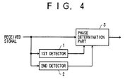
- FIG. 4 is a system block diagram showing the general construction of a demodulator unit of a receiver apparatus according to the present invention.
- the demodulator unit shown in FIG. 4 includes a first detector 1 and a second detector 2 which detect the absolute phase of signal points of a received signal, and a phase determination part 3.
- the first detector 1 detects the absolute phase by a first phase detecting method
- the second detector 2 detects the absolute phase by a second phase detecting method.
- the second phase detecting method has a detection speed which is slower than that of the first phase detecting method or, has a detection accuracy which is higher than that of the first detecting method.
- the first detector 1 and he second detector 2 detect the absolute phase in parallel.
- the phase determination part 3 determines the absolute phase based on a phase detection result of the first detector 1 when the phase detection results of the first detector 1 and the second detector 2 are the same, and determines the absolute phase based on the phase detection result of the second detector 2 when the phase detection results of the first detector 1 and the second detector 2 are mutually different.
- the absolute phase is determined based on the phase detection result of the first detector 1 in this case, and the absolute phase can be detected at a high speed.
- the phase detection results of the first and second detectors 1 and 2 may become the same.
- the absolute phase is determined based on the phase detection result of the first detector 1, and thus, it is possible to detect the absolute phase at a high speed.
- the phase detection results of the first and second detectors 1 and 2 are mutually different, it is possible to determine the absolute phase based on the phase detection result of the second detector 2 at the time when it is found that the phase detection results of the first and second detectors 1 and 2 are mutually different, thereby enabling a high-speed correction of the detected phase.
- the absolute phase is once provisionally detected based on the phase detection result of the first detector 1, regardless of the amount of noise included in the received signal, it is possible to detect the absolute phase at a high speed because the absolute phase which is provisionally determined based on the phase detection result of the first detector 1 is determined as being the absolute phase if the phase detection results of the first and second detectors 1 and 2 become the same.
- FIG. 5 is a system block diagram showing an embodiment of the receiver apparatus according to the present invention.
- the present invention is applied to a digital satellite broadcast system.
- a receiver apparatus 10 generally includes a down converter 11, a digital demodulator unit 12, and an audio/video decoder 13.
- the receiver apparatus 10 is coupled to an antenna 9 and a television (TV) monitor 15.
- the digital demodulator unit 12 includes a carrier demodulator part 21, an absolute phase detector part 22, and an error correction part 23.
- a signal which is modulated according to a digital modulation technique and is transmitted from a satellite 8 is received by the antenna 9, and a received signal is supplied to the down converter 11.
- the down converter 11 frequency-converts the received signal to a low frequency suited for a signal processing carried out at a latter stage, and a frequency converted received signal is supplied to the digital demodulator unit 12.
- the carrier demodulator part 21 demodulates the carrier of the received signal.
- the absolute phase detector part 22 detects the absolute phase of signal points of the received signal based on an output of the carrier demodulator part 21.
- the error correction part 23 corrects an error based on an output of the absolute phase detector part 22.
- the audio/video decoder 13 decodes an audio/video signal within the received signal based on the output of the error correction part 23 of the digital demodulator unit 12, and supplies a decoded audio/video signal to the TV monitor 15. Hence, the TV monitor 15 reproduces the sound and image based on the decoded audio/video signal.
- This embodiment of the receiver apparatus is characterized by the operation of particularly the absolute phase detector part 22 of the digital demodulator unit 12.
- known circuits and units may be used for parts other than the digital demodulator unit 12. Accordingly, it is also possible to use known circuits and units for the carrier demodulator part 21 and the error correction part 23 of the digital demodulator unit 12.
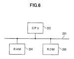
- the functions of the digital demodulator unit 12 may be realized by a computer system shown in FIG. 6.
- the computer system shown in FIG. 6 includes a CPU 202, a ROM 203 and a RAM 204 which are coupled to each other via a bus 201.
- the CPU 202 realizes the functions of the digital demodulator unit 12 by executing programs.
- the programs to be executed by the CPU 202 are stored in the ROM 203.
- the RAM 204 stores data including intermediate data obtained during computation processes carried out by the CPU 202.
- the ROM 203 and the RAM 204 may be formed by a single storage medium or, by independent storage mediums.
- various kinds of semiconductor devices, various kinds of disks including magnetic disks, optical disks and magnetooptical disks, card-shaped storage mediums and the like may be used as the storage medium.
- a disk drive which drives the disk is coupled to the bus 201.
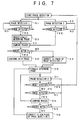
- FIG. 7 is a flow chart for explaining the operation of the CPU 202 of the computer system shown in FIG. 6 when realizing the operation of the absolute phase detector part 22 of the digital demodulator unit 12 by software.
- the process shown in FIG. 7 corresponds to an embodiment of the demodulating method according to the present invention.
- a step S1 detects the absolute phase of the signal points of the received signal which is obtained via the down converter 11 and the carrier demodulator part 21, using a first phase detecting method.
- a step S2 decides whether or not the absolute phase is detected. If the decision result in the step S2 is YES, a step S3 provisionally determines the absolute phase based on the detection result, and the process advances to a step S4.
- a step S5 detects the absolute phase of the signal points of the received signal which is obtained via the down converter 11 and the carrier demodulator part 21, using a second phase detecting method.
- This second phase detecting method has a detection speed which is slower than that of the first phase detecting method or, has a detection accuracy which is higher than that of the first phase detecting method.
- a range in which no detection error is generated with respect to the amount of noise included in the received signal is set larger for the second phase detecting method than the first phase detecting method. Hence, an erroneous detection is less likely to occur according to the second phase detecting method as compared to the first phase detecting method.
- a step S6 decides whether or not the absolute phase is detected, and the process advances to he step S4 if the decision result in the step S6 is YES.
- the step S4 compares the absolute phase detected by the first phase detecting method and the absolute phase detected by the second phase detecting method.
- a step S7 decides whether or not the compared absolute phases match. If the decision result in the step S7 is YES, a step S8 continues to use, as the absolute phase, the absolute phase which is detected by the first phase detecting method and is provisionally determined in the step S34, and the process advances to a step S10. On the other hand, if the decision result in the step S7 is NO, a step S9 corrects the absolute phase which is provisionally determined in the step S3 to the absolute phase which is detected by the second phase detecting method, and the process advances to the step S10. The step S10 finally determines the absolute phase based on the processes of the steps S8 and S9 described above and the process of a step S16 which will be described later.
- a step S11 detects the absolute phase of the signal points of the received signal by the second phase detecting method, and a step S12 decides whether or not a reset instruction by a reset signal or the like is detected. If the decision result in the step S12 is YES, the process returns to the steps S1 and S5 to restart the absolute phase detecting process.
- the reset instruction is issued when the CPU 202 detects that the digital demodulator unit 12 is not operating normally, for example.
- a step S13 decides whether or not the absolute phase is detected, and the process returns to the step S11 if the decision result in the step S13 is NO.
- a step S14 compares the absolute phase detected in the step S11 and the absolute phase finally determined in the step S10, and a step S15 decides whether or not the absolute phases compared in the step S14 match. If the decision result in the step S15 is YES, the process returns to the step S11. On the other hand, if the decision result in the step S15 is NO, the step S16 corrects the absolute phase to the absolute phase detected by the second phase detecting method, and the process thereafter returns to the step S10.
- the absolute phase in this case is determined based on the detection result of the first phase detecting method, and it is possible to detect the absolute phase at a high speed.
- the absolute phase detected by the first and second phase detecting methods becomes the same.
- the absolute phase is determined based on the detection result of the first phase detecting method, so that the absolute phase can be detected at a high speed.
- the detection results of the first and second phase detecting methods are mutually different, it is possible to determine the absolute phase based on the detection result of the second phase detecting method at the time when it is found that the detection results are mutually different, so that the absolute phase can be corrected at a high speed.
- the absolute phase is once provisionally determined based on the detection result of the first phase detecting method, regardless of the amount of noise included in the received signal, it is possible to determine, as the absolute phase, the absolute phase which is provisionally determined based on the detection result of the first phase detecting method if the detection results of the first and second phase detecting methods are the same, so that the absolute phase can be detected at a high speed.
- the phase may rotate due to the noise.
- this embodiment copes with such a rotation of the phase, by the steps S11 through S16.
- the amount of noise included in the received signal is large, and thus, measures are taken so that the absolute phase is detected by the second phase detecting method having the higher detection accuracy with respect to a change in the phase, unless the reset instruction is received.
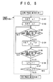
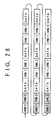
- FIG. 8 is a flow chart showing a first embodiment of the process of the step S1 shown in FIG. 7.
- a step S101 sets a number nl
- a step S102 sets a number ml.
- the number nl indicates a number of times the synchronizing signal within the received signal, such as that shown in FIG. 3, is consecutively received.
- the number m1 indicates a tolerable number of bit errors within the synchronizing signal.
- a step S103 decides whether or not a synchronization detection is made based on the synchronizing signal under a condition that the actual number of bit errors is less than or equal to the tolerable number ml.
- the third bit "1” should originally be a bit "0” in the case of the synchronizing signal, and the actual number of bit errors is 1.
- the actual number of bit errors in this case is less than or equal to the tolerable number m1 of bit errors, thereby making the decision result of the step S103 YES.
- the seventh bit “0” should originally be a bit "1" in the case of the synchronizing signal, and the actual number of bit errors is 1.
- the actual number of bit errors in this case is less than or equal to the tolerable number m1 of bit errors, thereby making the decision result of the step S105 YES.
- the decision result of the step S107 becomes YES, and the phase with which the synchronization is consecutively detected 2 times is detected as the absolute phase of the signal point of the received signal.
- the first phase detecting method detects the absolute phase by appropriately setting the number nl of times the synchronizing signal is consecutively received, and judging the synchronization detection depending on the number of times the synchronizing signal is periodically received from an existing phase detecting range.
- the tolerable number m1 of bit errors it becomes possible to receive the synchronizing signal even if an error of an arbitrary number of bits is generated in the synchronizing signal.
- the synchronizing signal is normally made up of a plurality of bits, the detection of the synchronizing signal becomes difficult as the amount of noise becomes large.
- this embodiment enables detection of the synchronizing signal by tolerating the generation of an error in 1 bit among the 8 bits. For this reason, it becomes possible to detect the synchronizing signal even when the amount of noise is large, and the absolute phase of the signal points of the received signal can be detected at a high speed.
- FIG. 9 is a flow chart showing a modification of the first embodiment shown in FIG. 8 of the process of the step S1 shown in FIG. 7.
- a step S100 carries out an error correction process with respect to the received signal, and the process advances to the step S101. Thereafter, the process is carried out similarly to that shown in FIG. 8.
- the error correction process is carried out with respect to the received signal before detecting the absolute phase by the first phase detecting method. Consequently, it is possible to improve the detection accuracy of the absolute phase detected by the first phase detecting method which has a high detection speed.
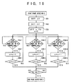
- FIG. 10 is a flow chart showing a first embodiment of the process of the step S5 shown in FIG. 7.
- a step S501 sets a threshold n2 of the number of times the synchronizing signal within the received signal, such as that shown in FIG. 3, is received.
- a step S502 sets a tolerable number m2 of bit errors within the synchronizing signal.
- a step S504 decides whether or not a synchronization detection is made based on the synchronizing signal under the condition that the actual number of bit errors is less than or equal to the tolerable number m2 of bit errors.
- the synchronizing signal has 8 bits with a pattern "10011010”
- the seventh bit "0” should originally be a bit "1” in the case of the synchronizing signal, and the actual number of bit errors is 1.
- the actual number of bit errors in this case is less than or equal to the tolerable number m2 of bit errors, thereby making the decision result of the step S504 YES.
- the decision result of the step S506 becomes YES, and the phase with which the synchronization is detected 10000 times in accumulation is detected as the absolute phase of the signal point of the received signal.
- the second phase detecting method detects the absolute phase by appropriately setting the threshold n2 of the number of times the synchronizing signal is received, and judging the synchronization detection depending on the accumulation of the number of times the synchronizing signal is periodically received from an existing phase detecting range.
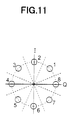
- the phase can take the positions of the data 1 through 8 shown in FIG. 11, and 8 kinds of phases can exist.
- this embodiment can accurately detect the absolute phase by detecting a phase with which the synchronizing signal is most received by accumulating the number of times the synchronizing signal is received with that phase. Since the noise is mixed about the centers of the 8 points of the data 1 through 8 shown in FIG. 11, it is possible to detect the phase with which the synchronizing signal is most received from a distribution of the received synchronizing signals by detecting the synchronizing signal for each phase, and the absolute phase can be detected based on the detected phase.
- the tolerable number m2 of bit errors it becomes possible to receive the synchronizing signal even if an error of an arbitrary number of bits is generated in the synchronizing signal.
- the synchronizing signal is normally made up of a plurality of bits, the detection of the synchronizing signal becomes difficult as the amount of noise becomes large.
- this embodiment enables detection of the synchronizing signal by tolerating the generation of an error in 1 bit among the 8 bits. For this reason, it becomes possible to detect the synchronizing signal even when the amount of noise is large, and the absolute phase of the signal points of the received signal can be detected at a high speed.
- FIG. 12 is a flow chart showing a second embodiment of the processes of the steps S1 and S5 shown in FIG. 7.
- the absolute phase detecting processes are carried out in parallel with respect to the existing phase detecting range.
- steps S21-1 through S21-n detect the absolute phases in parallel with respect to the corresponding phase detecting ranges.
- a step S23 determines, as the absolute phase, the absolute phase which is detected most quickly among the absolute phases detected by the steps S21-1 through S21-n.
- n 8 and 8 kinds of phases exist.
- the steps S21-1 through S21-8 of this embodiment detect the absolute phases in parallel with respect to the corresponding phase detecting ranges. For this reason, it is possible to detect the absolute phase at a high speed.
- 8 phase detector parts are operated in parallel.
- FIG. 13 is a flow chart showing a third embodiment of the processes of the steps S1 and S5 shown in FIG. 7.
- the absolute phase detecting process is successively carried out on a time base, with respect to the existing phase detecting range.
- a step S31 sets a detection time t.
- a step S32-1 detects the absolute phase with respect to a corresponding phase detecting range.
- a step S33-1 decides whether or not the detection of the absolute phase by the step S32-1 ends within the time t, and a step S34 determines the absolute phase to the detected absolute phase if the decision result in the step S33-1 is YES.
- a step S33-2 detects the absolute phase with respect to a corresponding phase detecting range.
- a step S33-3 decides whether or not the detection of the absolute phase by the step S33-2 ends within the time t, and the step S34 determines the absolute phase to the detected absolute phase if the decision result in the step S33-3 is YES.
- a step S32-n detects the absolute phase with respect to a corresponding phase detecting range.
- a step S33-n decides whether or not the detection of the absolute phase by the step S32-n ends within the time t, and the step S34 determines the absolute phase to the detected absolute phase if the decision result in the step S33-n is YES.
- the process returns to the step S32-1 if the decision result in the step S33-n is NO.
- n 8 and 8 kinds of phases exist.
- the steps S32-1 through S33-8 of this embodiment successively detect the absolute phases with respect to the corresponding phase detecting ranges. For this reason, when carrying out the processes of the steps S32-1 through S33-8 by hardware, 1 phase detector part can be operated successively with respect to each of the phase detecting ranges, and the scale of the hardware can be reduced.
- the absolute phase detection time is reduced by overlapping mutually adjacent phase detecting ranges which are used to detect the absolute phase by the first or second phase detecting method in the second and third embodiments described above.
- the mutually adjacent phase detecting ranges which are used when detecting the absolute phase are arranged to overlap each other. More particularly, as shown in FIG. 15, the phase detecting range R1 is spread on one side so as to overlap the adjacent phase detecting range R2, and the phase detecting range R1 is spread on the other side so as to overlap the adjacent phase detecting range R8. As a result, the amount of signal detected within the phase detecting range R1 increases, and it becomes possible to accurately detect the signal existing within the phase detecting range R1 at a high speed.
- Each of the adjacent phase detecting ranges R2 and R8 are similarly spread to overlap the phase detecting ranges adjacent thereto.
- the increase in the amount of signal detected within the phase detecting ranges R2 and R8 by the spreading of the phase detecting ranges R2 and R8 is extremely small compared to the increase in the amount of signal detected within the phase detecting range R1 by the spreading of the phase detecting range R1, and consequently, it is possible to positively detect the signal existing within the phase detecting range R1.
- the absolute phase is detected by the first or second phase detecting method as in the first and second embodiments described above, even in a case where signals having different degrees of multi-value (degrees of modulation) coexist within the received signal.
- the transmission itself of a modulated signal in which signals having different degrees of multi-value (degrees of modulation) coexist is discussed in Katoh et al., "A Study On Satellite ISDB Transmission System", Video Information Media Society Technical Report, Vol.21, No.25, pp.1-5, BSC97-12 (March 1997), and a description of such a transmission itself will be omitted in this specification.
- this embodiment adjusts the phase detecting range to the modulation technique having the higher degree of modulation, that is, to the 8PSK, so as to also cover the phase detecting range of the modulation technique having a lower degree of modulation.
- the absolute phase of the signal modulated by the 8PSK is detected using 8 kinds of phase detecting ranges R1 through R8 as shown in FIG.
- the phase detecting ranges R1, R3, R5 and R7 or, the phase detecting ranges R2, R4, R6 and R8 of the QPSK having the lower degree of modulation than the 8PSK are covered by the phase detecting ranges R1 through R8 of the 8PSK having the higher degree of modulation.
- the absolute phase of the signal points of the received signal is detected by the first phase detecting method, based on 1 kind of synchronizing signal or a plurality of kinds of synchronizing signals.
- FIG. 17 is a flow chart showing the sixth embodiment of the process of the step S1 shown in FIG. 7.
- a step S41 sets a number nl of times N kinds of synchronizing signals within the received signal are consecutively received, where N is an arbitrary integer.
- a step S42 sets a tolerable number m1 of bit errors within the synchronizing signal.
- step S43-i or S45-i the process returns to the step S43-i.
- step S45-i YES
- a step S47-i decides whether or not the number s of times the synchronizing signal i is received is equal to the number nl of times the synchronizing signal i is consecutively received. The process returns to the step S45-i if the decision result in the step S47-i is NO. If the decision result in the step S47-i is YES, the process advances to a step S48.
- the step S48 decides whether or not the decision result is YES for all of the steps S47-1 through S47-N, and the process ends if the decision result in the step S48 is YES.
- the steps S41, S42, and S43-i through S47-i respectively correspond to the steps S101 through S107 described above in conjunction with FIG. 8.
- the first phase detecting method appropriately sets the number nl of times the N kinds of synchronizing signals are consecutively received, and detects the absolute phase from the existing phase detecting range, by judging the synchronization detection from the number of times the 1 or N or less kinds of periodically received synchronizing signals are consecutively received.
- the tolerable number m1 of bit errors it becomes possible to receive the 1 or N or less kinds of synchronizing signals even if an error of an arbitrary number of bits is generated in the 1 or N or less kinds of synchronizing signals.
- the synchronizing signal is normally made up of a plurality of bits, the detection of the synchronizing signal becomes difficult as the amount of noise becomes large.
- this embodiment enables detection of the synchronizing signal by tolerating the generation of an error in 1 bit among the 8 bits. For this reason, it becomes possible to detect the 1 or N or less kinds of synchronizing signals even when the amount of noise is large, and the absolute phase of the signal points of the received signal can be detected at a high speed.
- step S1 when the step S1 is started, it is possible to carry out an error correction process with respect to the received signal as in the step S100 shown in FIG. 9, before carrying out the step S41 shown in FIG. 17.
- the error correction process is carried out with respect to the received signal before the absolute phase is detected by the first phase detecting method, it is possible to improve the detection accuracy of the absolute phase detection carried out by the first phase detecting method which has the high detection speed.
- the absolute phase of the signal points of the received signal is detected by the second phase detecting method, based on 1 kind of synchronizing signal or a plurality of kinds of synchronizing signals.
- FIG. 18 is a flow chart showing the sixth embodiment of the process of the step S5 shown in FIG. 7.
- a step S51 sets a threshold n2 of the number of times N kinds of synchronizing signals within the received signal are received, where N is an arbitrary integer.
- a step S52 sets a tolerable number m2 of bit errors within the synchronizing signal.
- the step S54-i is repeated if the decision result in the step S54-i is NO.
- a step S56-i decides whether or not the number s of times the synchronizing signal i is received is equal to the threshold n2 of the number of times the synchronizing signal i is received.
- the process returns to the step S54-i if the decision result in the step S56-i is NO. If the decision result in the step S56-i is YES, the process advances to a step S57.
- the step S57 decides whether or not the decision result is YES for all of the steps S56-1 through S56-N, and the process ends if the decision result in the step S57 is YES.
- the steps S51 through S53 and S54-i through S56-i respectively correspond to the steps S501 through S506 described above in conjunction with FIG. 10.
- the second phase detecting method appropriately sets the threshold n2 of the number of times the N kinds of synchronizing signals are received, and detects the absolute phase from the existing phase detecting range, by judging the synchronization detection from the accumulation of the number of times the 1 or N or less kinds of periodically received synchronizing signals are received.
- the tolerable number m2 of bit errors it becomes possible to receive the 1 or N or less kinds of synchronizing signals even if an error of an arbitrary number of bits is generated in the 1 or N or less kinds of synchronizing signals.
- the synchronizing signal is normally made up of a plurality of bits, the detection of the synchronizing signal becomes difficult as the amount of noise becomes large.
- this embodiment enables detection of the synchronizing signal by tolerating the generation of an error in 1 bit among the 8 bits. For this reason, it becomes possible to detect the 1 or N or less kinds of synchronizing signals even when the amount of noise is large, and the absolute phase of the signal points of the received signal can be detected at a high speed.
- the number nl of times the synchronizing signal is consecutively received, the tolerable number m1 of bit errors, the threshold n2 of the number of times the synchronizing signal is received, and the tolerable number m2 of bit errors are respectively set in common with respect to the N kinds of synchronizing signals.
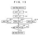
- the absolute phase of the signal points of the received signal is detected by the first phase detecting method by independently providing protection stages for the synchronization detection in synchronizing signal parts of the one or plurality of synchronizing signals.
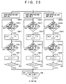
- FIGS. 19 and 20 those steps which are the same as those corresponding steps in FIG. 17 are designated by the same reference numerals, and a description thereof will be omitted.
- a step S62 decides whether or not two or more kinds of synchronizing signals are detected, and the process ends if the decision result in the step S62 becomes YES.
- Each step S61-i carries out the process shown in FIG. 20 with respect to the corresponding kind of synchronizing signal i.
- Steps S65-1 through S65-M are carried out in parallel, where M is an arbitrary integer.
- the synchronization is not detected unless the synchronizing signal is consecutively detected nl times at all of the synchronizing signal positions, it is possible to detect the absolute phase even if there exists a synchronizing signal position where the synchronizing signal is not consecutively detected nl times due to noise.
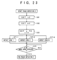
- the absolute phase of the signal points of the received signal is detected by the second phase detecting method by independently providing protection stages for the synchronization detection in synchronizing signal parts of the one or plurality of synchronizing signals.
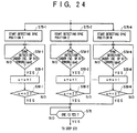
- FIGS. 23 and 24 those steps which are the same as those corresponding steps in FIG. 18 are designated by the same reference numerals, and a description thereof will be omitted.
- steps S71-1 through S71-N are then carried out in parallel.
- a step S72 decides whether or not two or more kinds of synchronizing signals are detected, and the process ends if the decision result in the step S72 becomes YES.
- Each step S71-i carries out the process shown in FIG. 24 with respect to the corresponding kind of synchronizing signal i.
- Steps S75-1 through S75-M are carried out in parallel, where M is an arbitrary integer.
- the synchronization is not detected unless the synchronizing signal is detected n2 times at all of the synchronizing signal positions, it is possible to detect the absolute phase even if there exists a synchronizing signal position where the synchronizing signal is not detected n2 times due to noise.
- the absolute phase of the signal points of the received signal is detected by the first phase detecting method by independently providing protection stages for the synchronization error detection in synchronizing signal parts of the one or plurality of synchronizing signals.
- a step S78 starts a synchronization detection process, and a step S79 decides whether or not the synchronization detection was successful.
- the process returns to the step S78 if the decision result in the step S79 is NO.
- the process advances to a step S80 if the decision result in the step S79 is YES.
- the steps S78 and S79 may carry out the synchronization detection by the process shown in FIG. 17 or FIG. 19 described above.
- the step S80 starts a synchronization error detection process.
- a step S81 sets a number n3 of times the synchronizing signal is consecutively lost, and a step S82 sets a tolerable number m3 of bit errors within the synchronizing signal.
- a step S83-i detects a synchronization error in a corresponding synchronizing signal i from among the N kinds of synchronizing signals.
- a step S84-i decides whether or not (N-1) or more synchronization errors are detected, including the other kinds of synchronizing signals. If the decision result in the step S84-i is YES, a step S86 ends the synchronization error detection process, and the process returns to the step S78.
- a step S85-i decides whether or not the synchronization of the corresponding kind of synchronizing signal i is established.
- the process returns to the step S84-i if the decision result in the step S85-i is NO.
- the process returns to the step S83-i if the decision result in the step S85-i is YES.
- Each step S83-i carries out the process shown in FIG. 26 with respect to the corresponding kind of synchronizing signal i.
- Steps S801-1 through S801-M are carried out in parallel, where M is an arbitrary integer.
- a step S802-j decides whether or not the synchronization is lost when the number of bit errors is less than or equal to the tolerable number m3 of bit errors.
- a step S804-j decides whether or not the synchronization is lost when the number of bit errors is less than or equal to the tolerable number m3 of bit errors. The process returns to the step S802-j if the decision result in the step S804-j is NO.
- the absolute phase of the signal points of the received signal is detected by the second phase detecting method by independently providing protection stages for the synchronization error detection in synchronizing signal parts of the one or plurality of synchronizing signals.
- a step S88 starts a synchronization detection process, and a step S89 decides whether or not the synchronization detection was successful.
- the process returns to the step S88 if the decision result in the step S89 is NO.
- the process advances to a step S90 if the decision result in the step S89 is YES.
- the steps S88 and S89 may carry out the synchronization detection by the process shown in FIG. 18 or FIG. 23 described above.
- the step S90 starts a synchronization error detection process.
- a step S91 sets a threshold n4 of the number of times the synchronizing signal is received, and a reception time T.
- a step S92 sets a tolerable number m4 of bit errors within the synchronizing signal.
- a step S95-i decides whether or not (N-1) or more synchronization errors are detected, including the other kinds of synchronizing signals.
- a step S97 ends the synchronization error detection process if the decision result in the step S95-i is YES, and the process returns to the step S88.
- a step S96-i decides whether or not the synchronization of the corresponding kind of synchronizing signal i is established.
- the process returns to the step S95-i if the decision result in the step S96-i is NO.
- the process returns to the step S94-i if the decision result in the step S96-i is YES.
- Each step S94-i carries out the process shown in FIG. 30 with respect to the corresponding kind of synchronizing signal i.
- Steps S901-1 through S901-M are carried out in parallel, where M is an arbitrary integer.
- a step S902-j resets a synchronizing signal detection time, and a step S903-j decides whether or not the synchronization is lost when the number of bit errors is less than or equal to the tolerable number m4 of bit errors.
- a step S905-j decides whether or not the synchronizing signal detection time is longer than the reception time T. If the decision result in the step S905-j is NO, a step S906-j decides whether or not the number s2 of times the synchronizing signal is received is equal to the threshold n4 of the number of times the synchronizing signal is received.
- step S906-j If the decision result in the step S906-j is NO, the process returns to the step S903-j. In addition, if the decision result in the step S906-j is YES, the process returns to the step S901-j. On the other hand, if the decision result in the step S905-j is YES, a step S907-j decides whether or not the synchronizing signal detection time is longer than the reception time T at (M-1) or more synchronizing signal positions, including the other kinds of synchronizing signals. If the decision result in the step S907-j is YES, a step S909 ends the synchronization error detection, and the process returns to the step S95-i shown in FIG. 29.
- a step S908-j decides whether or not the synchronization is established at the synchronizing signal position j.
- the process returns to the step S907-j if the decision result in the step S908-j is NO.
- the process returns to the step S901-j if the decision result in the step S908-j is YES.
- the present invention is applied to the digital satellite broadcast system.
- the present invention is of course similarly applicable to any communication system which is constructed to demodulate the received signal which is received by a demodulator unit, by detecting the absolute phase of the signal points of the received signal.
Landscapes
- Engineering & Computer Science (AREA)
- Computer Networks & Wireless Communication (AREA)
- Signal Processing (AREA)
- Digital Transmission Methods That Use Modulated Carrier Waves (AREA)
- Synchronisation In Digital Transmission Systems (AREA)
Applications Claiming Priority (2)
| Application Number | Priority Date | Filing Date | Title |
|---|---|---|---|
| JP12107398 | 1998-04-30 | ||
| JP12107398A JP3558869B2 (ja) | 1998-04-30 | 1998-04-30 | 復調方法及び受信装置 |
Publications (3)
| Publication Number | Publication Date |
|---|---|
| EP0954145A2 true EP0954145A2 (fr) | 1999-11-03 |
| EP0954145A3 EP0954145A3 (fr) | 2003-11-19 |
| EP0954145B1 EP0954145B1 (fr) | 2006-06-14 |
Family
ID=14802184
Family Applications (1)
| Application Number | Title | Priority Date | Filing Date |
|---|---|---|---|
| EP99400967A Expired - Lifetime EP0954145B1 (fr) | 1998-04-30 | 1999-04-21 | Démodulateur à deux détecteurs de phase ayant différentes méthodes de détection |
Country Status (4)
| Country | Link |
|---|---|
| US (1) | US6535566B1 (fr) |
| EP (1) | EP0954145B1 (fr) |
| JP (1) | JP3558869B2 (fr) |
| DE (1) | DE69931842T2 (fr) |
Families Citing this family (6)
| Publication number | Priority date | Publication date | Assignee | Title |
|---|---|---|---|---|
| EP1061746A1 (fr) * | 1999-06-14 | 2000-12-20 | Sony International (Europe) GmbH | Décodeur de canal pour un récepteur de radiodiffusion numérique |
| JP4207329B2 (ja) * | 1999-09-20 | 2009-01-14 | 富士通株式会社 | フレーム同期回路 |
| US7106820B2 (en) * | 2001-04-10 | 2006-09-12 | Broadcom Corporation | System and method for establishing word synchronization |
| US7428284B2 (en) * | 2005-03-14 | 2008-09-23 | Micron Technology, Inc. | Phase detector and method providing rapid locking of delay-lock loops |
| US9119132B2 (en) * | 2007-10-10 | 2015-08-25 | Qualcomm Incorporated | Efficient system identification schemes for communication systems |
| KR101967169B1 (ko) * | 2012-05-16 | 2019-04-09 | 삼성전자주식회사 | 디바이스간 네트워크에서 동기화 방법 및 장치 |
Family Cites Families (5)
| Publication number | Priority date | Publication date | Assignee | Title |
|---|---|---|---|---|
| US4538120A (en) * | 1983-12-19 | 1985-08-27 | Rca Corporation | Carrier recovery loop for reception of quadraphase shift keyed signals |
| JPS6412556A (en) | 1987-07-07 | 1989-01-17 | Sumitomo Electric Industries | Package sealing device |
| US4959617A (en) * | 1989-05-30 | 1990-09-25 | Motorola, Inc. | Dual state phase detector having frequency steering capability |
| JPH0614069A (ja) | 1992-06-29 | 1994-01-21 | Hitachi Ltd | ディジタル角度変調信号復調回路の同期検出装置 |
| JP3276282B2 (ja) * | 1995-12-28 | 2002-04-22 | 日本放送協会 | 絶対位相検出器およびディジタル変調波復調装置 |
-
1998
- 1998-04-30 JP JP12107398A patent/JP3558869B2/ja not_active Expired - Fee Related
-
1999
- 1999-04-21 DE DE69931842T patent/DE69931842T2/de not_active Expired - Lifetime
- 1999-04-21 EP EP99400967A patent/EP0954145B1/fr not_active Expired - Lifetime
- 1999-04-22 US US09/298,052 patent/US6535566B1/en not_active Expired - Lifetime
Also Published As
| Publication number | Publication date |
|---|---|
| DE69931842D1 (de) | 2006-07-27 |
| JP3558869B2 (ja) | 2004-08-25 |
| EP0954145A3 (fr) | 2003-11-19 |
| EP0954145B1 (fr) | 2006-06-14 |
| JPH11313120A (ja) | 1999-11-09 |
| US6535566B1 (en) | 2003-03-18 |
| DE69931842T2 (de) | 2007-01-04 |
Similar Documents
| Publication | Publication Date | Title |
|---|---|---|
| US7313086B2 (en) | OFDM receiver, semiconductor integrated circuit and OFDM method for receiving a signal | |
| US4885756A (en) | Method of demodulating digitally modulated signals, and apparatus implementing such a method | |
| US8750424B2 (en) | Signal receiving apparatus, signal receiving method and signal receiving program | |
| KR100394200B1 (ko) | 직교 위상 복조 회로 | |
| CN102098466B (zh) | 接收装置、接收方法、接收程序和接收系统 | |
| EP1001580A1 (fr) | Démodulateur pour un signal modulé par sauts de phase avec estimateur de séquence à maximum de vraisemblance | |
| CN102075489A (zh) | Qam载波恢复的方法和系统 | |
| EP0913958B1 (fr) | Dispositif de réception à diversité | |
| JP3153869B2 (ja) | フェージング歪補償方式及びその回路 | |
| EP0954145B1 (fr) | Démodulateur à deux détecteurs de phase ayant différentes méthodes de détection | |
| US4283682A (en) | Erasure zone decision feedback phase lock loop for carrier recovery in data modems | |
| US7529321B1 (en) | Radio digital signal receiver | |
| US8234684B2 (en) | Digital detector for ATSC digital television signals | |
| US7180962B2 (en) | Apparatus and method for demodulation using detection of channel adaptive modulation scheme | |
| US6505220B1 (en) | Method and apparatus for detecting a unique word | |
| US6836518B1 (en) | Synchronization control method for receiver apparatus of data transmission system utilizing orthogonal frequency division multiplex, and data transmission system | |
| US7369622B2 (en) | Diversity circuit demodulating OFDM-method signals and diversity receiving apparatus having said diversity circuit therein | |
| US6993096B1 (en) | BS digital broadcasting receiver | |
| CN113810078B (zh) | 通信系统、通信方法及计算机存储介质 | |
| US6028475A (en) | Method and apparatus for demodulating multi-level QAM signal | |
| US7164733B1 (en) | Method and device for compensating for digital data demodulation phase uncertainty | |
| US7006584B1 (en) | Demodulator and demodulating method for mobile phone | |
| US20170346599A1 (en) | Apparatus and method for supporting cooperative transmission | |
| JPH0677941A (ja) | ダイバーシチ無線送受信方式 | |
| JPH07114424B2 (ja) | 搬送波同期復調装置 |
Legal Events
| Date | Code | Title | Description |
|---|---|---|---|
| PUAI | Public reference made under article 153(3) epc to a published international application that has entered the european phase |
Free format text: ORIGINAL CODE: 0009012 |
|
| AK | Designated contracting states |
Kind code of ref document: A2 Designated state(s): AT BE CH CY DE DK ES FI FR GB GR IE IT LI LU MC NL PT SE |
|
| AX | Request for extension of the european patent |
Free format text: AL;LT;LV;MK;RO;SI |
|
| PUAL | Search report despatched |
Free format text: ORIGINAL CODE: 0009013 |
|
| AK | Designated contracting states |
Kind code of ref document: A3 Designated state(s): AT BE CH CY DE DK ES FI FR GB GR IE IT LI LU MC NL PT SE |
|
| AX | Request for extension of the european patent |
Extension state: AL LT LV MK RO SI |
|
| 17P | Request for examination filed |
Effective date: 20040513 |
|
| AKX | Designation fees paid |
Designated state(s): DE FR |
|
| 17Q | First examination report despatched |
Effective date: 20040802 |
|
| RTI1 | Title (correction) |
Free format text: DEMODULATOR WITH TWO PHASE DETECTORS HAVING DIFFERENT DETECTING METHODS |
|
| GRAP | Despatch of communication of intention to grant a patent |
Free format text: ORIGINAL CODE: EPIDOSNIGR1 |
|
| GRAS | Grant fee paid |
Free format text: ORIGINAL CODE: EPIDOSNIGR3 |
|
| GRAA | (expected) grant |
Free format text: ORIGINAL CODE: 0009210 |
|
| AK | Designated contracting states |
Kind code of ref document: B1 Designated state(s): DE FR |
|
| REF | Corresponds to: |
Ref document number: 69931842 Country of ref document: DE Date of ref document: 20060727 Kind code of ref document: P |
|
| ET | Fr: translation filed | ||
| PLBE | No opposition filed within time limit |
Free format text: ORIGINAL CODE: 0009261 |
|
| STAA | Information on the status of an ep patent application or granted ep patent |
Free format text: STATUS: NO OPPOSITION FILED WITHIN TIME LIMIT |
|
| 26N | No opposition filed |
Effective date: 20070315 |
|
| REG | Reference to a national code |
Ref country code: FR Ref legal event code: TP |
|
| PGFP | Annual fee paid to national office [announced via postgrant information from national office to epo] |
Ref country code: FR Payment date: 20090417 Year of fee payment: 11 |
|
| REG | Reference to a national code |
Ref country code: FR Ref legal event code: ST Effective date: 20101230 |
|
| PG25 | Lapsed in a contracting state [announced via postgrant information from national office to epo] |
Ref country code: FR Free format text: LAPSE BECAUSE OF NON-PAYMENT OF DUE FEES Effective date: 20100430 |
|
| REG | Reference to a national code |
Ref country code: DE Ref legal event code: R082 Ref document number: 69931842 Country of ref document: DE Representative=s name: REICHERT & LINDNER PARTNERSCHAFT PATENTANWAELT, DE |
|
| REG | Reference to a national code |
Ref country code: DE Ref legal event code: R082 Ref document number: 69931842 Country of ref document: DE Representative=s name: REICHERT & LINDNER PARTNERSCHAFT PATENTANWAELT, DE Effective date: 20150512 Ref country code: DE Ref legal event code: R081 Ref document number: 69931842 Country of ref document: DE Owner name: SOCIONEXT INC., YOKOHAMA-SHI, JP Free format text: FORMER OWNER: FUJITSU SEMICONDUCTOR LTD., YOKOHAMA, KANAGAWA, JP Effective date: 20150512 |
|
| PGFP | Annual fee paid to national office [announced via postgrant information from national office to epo] |
Ref country code: DE Payment date: 20150414 Year of fee payment: 17 |
|
| REG | Reference to a national code |
Ref country code: DE Ref legal event code: R119 Ref document number: 69931842 Country of ref document: DE |
|
| PG25 | Lapsed in a contracting state [announced via postgrant information from national office to epo] |
Ref country code: DE Free format text: LAPSE BECAUSE OF NON-PAYMENT OF DUE FEES Effective date: 20161101 |