EP0954218B1 - Vorrichtung für melkstand - Google Patents
Vorrichtung für melkstand Download PDFInfo
- Publication number
- EP0954218B1 EP0954218B1 EP98901625A EP98901625A EP0954218B1 EP 0954218 B1 EP0954218 B1 EP 0954218B1 EP 98901625 A EP98901625 A EP 98901625A EP 98901625 A EP98901625 A EP 98901625A EP 0954218 B1 EP0954218 B1 EP 0954218B1
- Authority
- EP
- European Patent Office
- Prior art keywords
- cabinet
- milking
- driving
- stall
- inner space
- Prior art date
- Legal status (The legal status is an assumption and is not a legal conclusion. Google has not performed a legal analysis and makes no representation as to the accuracy of the status listed.)
- Revoked
Links
- 241001465754 Metazoa Species 0.000 claims abstract description 14
- 239000000725 suspension Substances 0.000 claims description 2
- 210000000078 claw Anatomy 0.000 description 8
- 239000008267 milk Substances 0.000 description 8
- 210000004080 milk Anatomy 0.000 description 8
- 235000013336 milk Nutrition 0.000 description 8
- 241000283690 Bos taurus Species 0.000 description 7
- 210000002445 nipple Anatomy 0.000 description 6
- 238000004140 cleaning Methods 0.000 description 4
- 238000004519 manufacturing process Methods 0.000 description 2
- 238000000034 method Methods 0.000 description 2
- 230000006866 deterioration Effects 0.000 description 1
- 230000002349 favourable effect Effects 0.000 description 1
- 239000007788 liquid Substances 0.000 description 1
- 230000010349 pulsation Effects 0.000 description 1
Images


Classifications
-
- A—HUMAN NECESSITIES
- A01—AGRICULTURE; FORESTRY; ANIMAL HUSBANDRY; HUNTING; TRAPPING; FISHING
- A01J—MANUFACTURE OF DAIRY PRODUCTS
- A01J5/00—Milking machines or devices
- A01J5/04—Milking machines or devices with pneumatic manipulation of teats
-
- A—HUMAN NECESSITIES
- A01—AGRICULTURE; FORESTRY; ANIMAL HUSBANDRY; HUNTING; TRAPPING; FISHING
- A01J—MANUFACTURE OF DAIRY PRODUCTS
- A01J5/00—Milking machines or devices
- A01J5/017—Automatic attaching or detaching of clusters
-
- A—HUMAN NECESSITIES
- A01—AGRICULTURE; FORESTRY; ANIMAL HUSBANDRY; HUNTING; TRAPPING; FISHING
- A01K—ANIMAL HUSBANDRY; AVICULTURE; APICULTURE; PISCICULTURE; FISHING; REARING OR BREEDING ANIMALS, NOT OTHERWISE PROVIDED FOR; NEW BREEDS OF ANIMALS
- A01K1/00—Housing animals; Equipment therefor
- A01K1/12—Milking stations
Definitions
- the present invention relates to a device for a milking stall according to the precharacterizing portion of claim 1, see US-A-3,789,798.
- a milking equipment with a lot of different components.
- These components comprise usually a milking member in the form of a number of teatcups which may be connected to a common claw, a long milk conduit connecting the claw to a milk-collecting member and to a vacuum source for transferring a milking vacuum to the teats, a holding member, or a so called service arm, for holding and supporting the long milk conduit, a pulsator arranged to provide a pulsating vacuum for a pulsating chamber in each teatcup, a remover for removing the milking member from the teats after the milking is finished, a control unit for controlling the vacuum level of the milking equipment and an operating panel for supervising and controlling of the milking procedure and the milking equipment. It is thereby known to provide these different components at different locations in the milking stall.
- a cabinet reduces the flexibility because it is more difficult to adapt the milking equipment to different stall configurations.
- stall configurations comprise, for instance, a centrally provided milking parlour with a plurality of animal positions provided at two sides of the parlour.
- a cabinet must be adapted to be mounted on both the sides, which in practice implies that the cabinet must be manufactured in different variants for being located at different operating positions in the milking stall.
- split configuration i.e.
- the remover, the pulsator, the indicating lamp etc. of one milking equipment are located at one animal, while the operating panel of this equipment is located at the animal at the adjacent position.
- the cabinet must be manufactured in a plurality of different variants.
- the remover which comprises a driving member and a cord extending between the driving member and the milking member, must be located at a determined position in the milking stall in relation to the animal to be milked to permit the milking member to be removed from the teats of the animal in a simple way.
- US-A-3,789,798 discloses a milking unit to be provided in a milking stall offering at least one milking position for an animal to be milked.
- a milking member is arranged to be attached to said animal for milking thereof.
- the milking unit comprises a structure arranged to comprise a driving arrangement provided in a driving position in order to remove the milking member from the animal after the milking is finished, and an operating panel by which the milking equipment is controllable.
- the milking unit is positionable in different operating positions.
- the object of the present invention is to remedy the above-mentioned problems and to provide a device which makes it possible, in a more flexible way, to collect a number of components of a milking equipment in one cabinet. More closely, it is aimed at such a cabinet which may be built of a small number of common parts for being located at different operating positions in the milking stall.
- the driving arrangement is provided to be positioned in the cabinet at different positions of at least two predetermined driving positions which are adapted to the first operating position and the second operating position, respectively.
- the same cabinet can be used at different operating positions in the milking stall.
- the same cabinet may be used for a location at two opposite sides of the milking parlour.
- the driving arrangement comprises a driving member and an elongated element, such as a cord, a wire, a chain or the like, which element is provided to connect the driving member to said milking member, and furthermore, the driving arrangement comprises a guide member provided to guide the path of the elongated element.
- the cabinet comprises a first attachment member, which is provided for the mounting of the cabinet in the milking stall and provided horizontally at distance from a horizontal centre line through the cabinet, and a second attachment member provided to position the driving member in one of said two driving positions in the inner space of the cabinet, in such a manner that said centre line intersects the driving member.
- the driving member will retain its position in the cabinet at both the operating positions.
- the cabinet, horizontally seen may advantageously be elongated with two opposite ends, wherein the first attachment member is provided in the vicinity of one of the ends and the other attachment member is provided in the vicinity of the other end. Thereby, a certain distance may be secured between the attachment point of the cabinet and the pulling point of the driving member, in such a manner that the driving member is able to pull out the milking member to a desired position after milking.
- the cabinet comprises a wall portion which is arranged to be mountable in one of a first turning position, in which the wall portion extends essentially vertically and is adapted to the first operating position, and a second turning position, in which the wall portion likewise extends essentially vertically but is turned 180° from its first turning position and is adapted to the second operating position.
- the cabinet may comprise a top portion and a bottom portion, which are mountable at the wall portion.
- the guide member may comprise a passage through the bottom portion for the elongated element.
- each of the top portion and the bottom portion may be mountable at the wall portion in a first rotational position which is adapted to the first operating position and in a second rotational position, in which the top portion or the bottom portion is horizontally rotated essentially 180° in relation to the first rotational position, wherein the second rotational position is adapted to the second operating position.
- the device also comprises an indicating lamp which is arranged to indicate when milking is going on and provided on the bottom portion, and a door portion arranged to close the inner space of the cabinet in an openable manner, wherein the operating panel is arranged on the door portion.
- the cabinet may comprise means for a pivotable suspension of the door portion along two opposite side edges of the door portion and the door portion may be suspendable with the aid of said means on one side edge when the cabinet is in the first operating position and suspendable with the aid of said means along a second side edge when the cabinet is in the second operating position.
- the milking stall comprises a first milking position and a first milking equipment, and a second milking position and a second milking equipment, wherein the driving member of the first milking equipment and the operating panel of the second milking equipment are received by the cabinet for the first milking equipment.
- control unit arranged to enable the control of the vacuum level of the milking equipment and provided in the inner space of the cabinet, a pulsator provided in the inner space of the cabinet, a passage provided in the bottom portion for a vacuum conduit arranged to extend between the pulsator and the milking member, a passage provided in the top portion for a vacuum conduit arranged to extend between the control unit and a vacuum source of the milking equipment, and a member provided in the top portion for the supply of fresh air to the inner space of the cabinet.
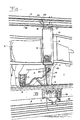
- Fig 1 shows the device according to the invention in a milking stall 1 at a milking position 2 where a cow 3 is present and is milked.
- the milking stall 1 comprises a milking equipment which comprises a lot of different components. It is to be noted that only some of the components necessary for the milking are shown in Fig 1. For example, no vacuum pump is shown.
- the milking equipment shown in Fig 1 comprises a milking member with a claw 4 and four teatcups 5 connected to the claw and each being attached to a teat of the cow 3. From the claw 4, a long milk conduit 6 extends to a milk flow meter 7 and from there to a milk transporting conduit 8.
- a cabinet 9 which comprises further components of the milking equipment.
- the cabinet 9 is attached to a wall arrangement 10 which forms a limit between the milking stall and a milking parlour in which the operator performing the milking is positioned.
- the cabinet 9 is attached by means of attachment members to be described more in detail below in connection with the description of Fig 4.
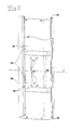
- the cabinet 9 comprises an operating panel 11 which is provided on a door portion 12 of the cabinet 9.
- the cabinet 9 is shown without the door portion and thereby the components appear which are provided in the inner space of the cabinet 9.
- a driving arrangement is provided, which comprises a driving member 13 housed in the cabinet 9.
- the driving member 13 comprises a pneumatic power cylinder which through an elongated element of the driving arrangement, in the embodiment disclosed a cord 14, is connected to the claw 4.
- the cabinet 9 also houses a control unit 15 by which the vacuum level of the milking equipment may be kept on and adjusted to a suitable level.
- the control unit 15 is via a vacuum conduit 16 connected to a system vacuum conduit 17.
- the control unit 15 is also connected to the pneumatic power cylinder of the driving member 13 and via a passage connected to ahapator 19 which is arranged to provide a pulsating vacuum for a pulsating chamber of each of the teatcups 5.
- the pulsating chambers of the teatcups 5 are via two pulsating conduits 20 connected to the pulsator 19.
- the long milk conduit 6 and the pulsating conduits 20 form together a bundle of conduits, which is held and supported by a support member 21 fixedly provided at the wall arrangement 10 and shaped as an arm protruding from the wall arrangement 10.
- the support member 21 is also arranged to support and guide the cord 14.
- the milking equipment comprises a fresh air conduit 22 which is connected to a fresh air channel 23 and arranged to supply fresh air to the inner space of the cabinet 9.
- a cleaning device 24 is disclosed, which has means for receiving the teatcups 5 after the milking is finished and for the supply of cleaning liquid to the teatcups 5 and the claw 4 via a cleaning conduit 25.
- a system conduit 26 is shown for different connections to, for instance, an electric current supply and an overall control system.
- a branching conduit 27 from the system conduit 26 leads, as shown in Fig 2, into the inner space of the cabinet 9 and is connected to a connecting terminal 18 which in turn is connected to the operating panel 11. From the operating panel 11, connections extend to different components of the cabinet 9.
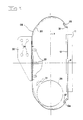
- Figs 3 and 4 show a wall portion 28 of the cabinet 9.
- the wall portion 28 is shaped like a sweep which extends around a great part of the cabinet 9 and encloses its inner space. Consequently, the wall portion 28 is produced by essentially one piece of a sheet.
- two attachment members 29 are provided at the wall portion 28, for example welded to a support sheet 30 which is attached to the wall portion 28.
- the attachment members 29 may certainly also be attached in another way, for example by rivet or screw connections.
- the attachment members 29 comprise a sheet strip arranged to extend around the driving member 13 and to be tightened against the driving member 13 by for example a screw connection 31 indicated in Fig 4.
- the wall portion 28 comprises a number of mounting members 32 which for example are welded to the wall portion and by means of which, the control unit 15 and the pulsator 19 may be mounted in the inner space of the cabinet 9.
- the mounting members 32 are provided symmetrically with respect to a horizontal centre axis x. This means, if the wall portion 28 is turned upside-down the control unit 15 and the pulsator 19 may be arranged in the same way as shown in Fig 2 in the turned cabinet 9, i.e. beneath the connecting terminal 18.
- the attachment members 29 are likewise provided identically and symmetrically with respect to the centre axis x which consequently will intersect the driving member 13.
- the driving member 13 may be provided into two opposite directions in the wall portion 28 in such a manner that the end from which the cord 14 extends always will point downwardly irrespective of the direction the cabinet 9.
- two attachment members 33 are provided at the wall portion 28 for the attachment of the cabinet 9 to the wall arrangement 10.
- the attachment holes 34 of the attachment members 33 are provided beside a vertical centre plane p, which extends through the cabinet 9 and the wall portion 28.
- the door portion 12 is pivotably attached to the wall portion 28 by means of two hinges 35 attached to the wall portion 28 at which a rod is attached. The rod extends through one of two passages 12a which each extends along one of the longitudinal side edges of the door portion 12.
- the door portion 12 is furthermore lockable by locking members not shown, which are provided in holes 36 in a C-shaped edge portion 37 of the wall portion 28.
- the wall portion 28 comprises two such parallel edge portions 37.
- Each edge portion 37 comprises two holes 36.
- the rod of the hinges 35 is furthermore releasably attached in such a manner that it may be moved from one side edge of the door portion 12 to the other opposite side edge, which means that the door portion 12, irrespective of in which direction it is being open, always may have the operating panel 11 provided in its lower part.
- the cabinet 9 has, seen horizontally, an elongated shape with the attachment holes 34 in the vicinity of one end and the attachment members 29 of the driving member 13 in the vicinity of the other end.
- the attachment holes 34 will consequently be located on the other side of the vertical centre plane p, with respect to the configuration shown in Fig 4. Likewise, the attachment members 29 of the driving member 13 will be moved from side of plane p as shown to the opposite side.
- Fig 5 shows a perspective view of a top portion 38 which delimits the inner space of the cabinet 9 upwardly.
- the top portion 38 comprises a passage 39 for the branching conduit 27 and possibly a set of cables, a second passage 40 for the fresh air conduit 22 and a third passage 41 for the vacuum conduit 16.
- Fig 6 shows a perspective view of a bottom portion 42 arranged to delimit the inner space of the cabinet 9 downwardly.
- the bottom portion 42 comprises an indicating lamp 43 arranged to indicate when milking is going on.
- the driving arrangement comprises guide means for guiding the pulling path of the cord 14 between the driving member 13 and the claw 4, i.e. except said support member 21 also a guide member in the shape of a first passage 44 through the bottom portion 42.
- the bottom portion 42 comprises two other passages 45 for the pulsation conduits 20.
- Both the top portion 38 and the bottom portion 42 are symmetrical in such a way that they may be rotated 180° and consequently take two different rotational positions in relation to the wall portion 28.
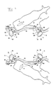
- Fig 7 shows the cabinet 9 according to the invention in four different operating positions in a milking stall 1 with four different milking positions 2, two on each side of a milking parlour. It is to be noted that all conduits and cables, like the milk conduit 6 and the pulsating conduits 20, have been omitted in Fig 7, which however shows the extension of the cord 14.
- the cabinet 9 is mounted in a so called left-straight position at A. This means that the cabinet 9 is provided to the left in the milking stall seen in a cow's free walking direction through the milking stall 1.
- the fact that the cabinet 9 is mounted in straight position means that all components, which are housed or comprised by the cabinet 9, belong to one and the same milking equipment for milking of a cow.
- the cabinet 9 according to the invention is mounted in so called left-split position.
- the cabinet 9 according to the invention is provided in a corresponding way as at A and B, respectively, but on the right side.
- the support member 21 is shown in two positions, a milking position by continuous lines and a parlour position by broken lines.
- the support member 21 comprises a spring element by which the support member 21 is forced to take the milking position.
- the milk conduit 6 and the pulsating conduits 20 are held in a suitable position during the milking and the milking member may easily be pulled off the teat by the driving member 13 and the cord 14.
- the continued pulling force of the driving member 13 which is applied to the cord 14 will move the support member 21 to the parlour position shown by broken lines, in which the teatcups 5 are easily accessible for cleaning and application to the next cow.
- the cabinet 9 may thus be positioned at the four operating positions A-D without deterioration of the function of the support member 21.
- the two attachment holes 34 closest to a centre line x are intended for the operating positions B and D, while the two attachment holes 34 farthest away from the centre line x are intended for the operating positions A and C.
- the attachment members 33 are thereby mounted on an arm 46 provided turnably to the wall arrangement 10. In the operating positions B and D, the horizontal centre axis x is essentially parallel to the arm 46 and in the operating positions A and C essentially perpendicular to the arm 46.
- the present invention is not restricted to the embodiments shown above but may be varied and modified within the scope of the following claims.
- the driving member 13 may be realized in other forms than a pneumatic power cylinder, for example as a hydraulic one or as an engine which is driven electrically, pneumatically or hydraulically. It is to be noted that the cabinet 9 not necessarily needs to comprise all the components disclosed and it may include further components, not shown.
Landscapes
- Life Sciences & Earth Sciences (AREA)
- Environmental Sciences (AREA)
- Animal Husbandry (AREA)
- Zoology (AREA)
- Biodiversity & Conservation Biology (AREA)
- External Artificial Organs (AREA)
- Ultra Sonic Daignosis Equipment (AREA)
- Cosmetics (AREA)
- Measurement Of The Respiration, Hearing Ability, Form, And Blood Characteristics Of Living Organisms (AREA)
- Perforating, Stamping-Out Or Severing By Means Other Than Cutting (AREA)
Claims (17)
- Vorrichtung für einen Melkstand (1) mit mindestens einer Melkposition (2) für ein Tier (3) und mit mindestens einer Melkausrüstung, umfassend ein Melkelement (4, 5), das zum Ansetzen an das Tier beim Melken dient, wobei die Vorrichtung ein Gehäuse (9) umfaßt, das einen Innenraum definiert, wobei das Gehäuse eine Antriebsanordnung (13) umfaßt, die zum Entfernen des Melkelementes (4, 5) vom Tier (3) dient, nachdem das Melken beendet ist, und ein Bedienfeld (11), mit dem die Melkausrüstung gesteuert werden kann, wobei das Gehäuse (9) in eine erste Betriebsposition (A, D) im Stand (1) gebracht werden kann oder in eine zweite Betriebsposition (B, C) im Stand (1), dadurch gekennzeichnet, daß die Antriebsanordnung (13, 14, 44) im Gehäuse (9) in verschiedene Positionen von mindestens zwei vorbestimmten Antriebspositionen gebracht werden kann, die an die erste Betriebsposition (A, D) bzw. die zweite Betriebsposition (B, C) angepaßt sind.
- Vorrichtung nach Anspruch 1, dadurch gekennzeichnet, daß die Antriebsanordnung (13, 14, 44) ein Antriebselement (13) umfaßt sowie ein längliches Element (14) wie ein Kabel, ein Draht, eine Kette oder ähnliches, wobei das Element (14) zum Verbinden des Antriebselementes (13) mit dem Melkelement dient, und daß die Antriebsanordnung (13,14,44) ein Führungselement (44) umfaßt, das das längliche Element (14) führt.
- Vorrichtung nach Anspruch 2, dadurch gekennzeichnet, daß das Gehäuse ein erstes Befestigungselement (33) umfaßt, das zum Befestigen des Gehäuses (9) am Melkstand (1) dient und horizontal beabstandet von einer horizontalen Linie (X) durch das Gehäuse (9) angeordnet ist, und ein zweites Befestigungselement (29), das zum Positionieren des Antriebselementes (13) in einer der beiden Antriebspositionen im Innenraum des Gehäuses (9) in einer solchen Weise dient, daß die Mittellinie (X) das Antriebselement (13) schneidet.
- Vorrichtung nach Anspruch 3, dadurch gekennzeichnet, daß das Gehäuse, horizontal gesehen, länglich mit zwei gegenüberliegenden Enden ausgebildet ist und daß das erste Befestigungselement (33) in der Nähe eines der Enden vorgesehen ist und das andere Befestigungselement (29) in der Nähe des anderen Endes.
- Vorrichtung nach einem der Ansprüche 1-4, dadurch gekennzeichnet, daß das Gehäuse (9) einen Wandabschnitt (28) umfaßt, der so angeordnet ist, daß er in einer ersten Drehposition befestigt werden kann, in der sich der Wandabschnitt (28) im wesentlichen vertikal erstreckt und an die erste Betriebsposition (A, D) angepaßt ist, und in einer zweiten Drehposition, in der sich der Wandabschnitt (28) in gleicher Weise im wesentlichen vertikal erstreckt, jedoch aus seiner ersten Drehposition im wesentlichen um 180° gedreht ist und an die zweite Betriebsposition (B, C) angepaßt ist.
- Vorrichtung nach Anspruch 5, dadurch gekennzeichnet, daß das Gehäuse einen oberen Abschnitt (38) und einen unteren Abschnitt (42) umfaßt, die am Wandabschnitt (28) befestigt werden können.
- Vorrichtung nach Anspruch 2 und 6, dadurch gekennzeichnet, daß das Führungselement einen Durchgang (44) durch den unteren Abschnitt (42) für das längliche Element (14) aufweist.
- Vorrichtung nach einem der Ansprüche 6 und 7, dadurch gekennzeichnet, daß sowohl der obere Abschnitt (38) als auch der untere Abschnitt (42) in einer ersten Drehposition am Wandabschnitt (28) befestigt werden können, die an die erste Betriebsposition (A, D) angepaßt ist, und in einer zweiten Drehposition, bei der der obere Abschnitt oder der untere Abschnitt (38, 42) im wesentlichen um 180° horizontal in Bezug auf die erste Drehposition gedreht ist, wobei die zweite Drehposition an die zweite Betriebsposition (B, C) angepaßt ist.
- Vorrichtung nach einem der Ansprüche 6-8, dadurch gekennzeichnet, daß sie auch eine Anzeigelampe (43) umfaßt, die dazu dient, anzuzeigen, daß das Melken stattfindet, und daß die Anzeigelampe (43) am Bodenabschnitt (42) vorgesehen ist.
- Vorrichtung nach einem der vorangegangenen Ansprüche, dadurch gekennzeichnet, daß das Gehäuse (9) einen Türabschnitt (12) umfaßt, der zum Abschließen des Innenraumes des Gehäuses (9) in einer zu öffnenden Weise dient, und daß das Bedienfeld (11) am Türabschnitt (12) vorgesehen ist.
- Vorrichtung nach Anspruch 10, dadurch gekennzeichnet, daß das Gehäuse eine Einrichtung (35) zum schwenkbaren Aufhängen des Türabschnittes (12) entlang zweier gegenüberliegenden Kanten des Türabschnittes umfaßt, und daß der Türabschnitt mit Hilfe der Einrichtung (35) an einer Seitenkante aufgehängt werden kann, wenn sich das Gehäuse in der ersten Betriebsposition (A, D) befindet, und mit der Hilfe der Einrichtung (35, 36) entlang der zweiten Seitenkante aufgehängt werden kann, wenn sich das Gehäuse in der zweiten Betriebsposition (B, C) befindet.
- Vorrichtung nach einem der vorangegangenen Ansprüche, dadurch gekennzeichnet, daß der Melkstand (1) eine erste Melkposition und eine erste Melkausrüstung umfaßt sowie eine zweite Melkposition und eine zweite Melkausrüstung und daß das Antriebselement (13) der ersten Melkeinrichtung und das Bedienfeld (11) der zweiten Melkausrüstung vom Gehäuse (9) für die erste Melkausrüstung aufgenommen werden.
- Vorrichtung nach einem der vorangegangenen Ansprüche, dadurch gekennzeichnet, daß sie auch eine Steuereinheit (15) umfaßt, die dazu dient, den Vakuumpegel der Melkausrüstung zu steuern, und die im Innenraum des Gehäuses (9) vorgesehen ist.
- Vorrichtung nach einem der vorangegangenen Ansprüche, dadurch gekennzeichnet, daß sie auch einen Pulsator (19) umfaßt, der im Innenraum des Gehäuses (9) vorgesehen ist.
- Vorrichtung nach Anspruch 5 und 14, dadurch gekennzeichnet, daß der Bodenabschnitt (42) mindestens einen Durchgang (45) für eine Vakuumleitung (20) umfaßt, die sich zwischen dem Pulsator (19) und dem Melkelement (4, 5) erstreckt.
- Vorrichtung nach Anspruch 13 und 15, dadurch gekennzeichnet, daß der obere Abschnitt (38) einen Durchgang für eine Vakuumleitung umfaßt, die sich zwischen der Steuereinheit und einer Vakuumquelle der Melkausrüstung befindet.
- Vorrichtung nach einem der vorangegangenen Ansprüche, dadurch gekennzeichnet, daß der obere Abschnitt (38) ein Element für die Zufuhr von Frischluft an den Innenraum des Gehäuses umfaßt.
Applications Claiming Priority (3)
| Application Number | Priority Date | Filing Date | Title |
|---|---|---|---|
| SE9700119A SE9700119D0 (sv) | 1997-01-17 | 1997-01-17 | Anordning för ett mjölkningsstall |
| SE9700119 | 1997-01-17 | ||
| PCT/SE1998/000062 WO1998031212A1 (en) | 1997-01-17 | 1998-01-15 | A device for a milking stall |
Publications (2)
| Publication Number | Publication Date |
|---|---|
| EP0954218A1 EP0954218A1 (de) | 1999-11-10 |
| EP0954218B1 true EP0954218B1 (de) | 2003-01-02 |
Family
ID=20405442
Family Applications (1)
| Application Number | Title | Priority Date | Filing Date |
|---|---|---|---|
| EP98901625A Revoked EP0954218B1 (de) | 1997-01-17 | 1998-01-15 | Vorrichtung für melkstand |
Country Status (7)
| Country | Link |
|---|---|
| US (1) | US6336424B1 (de) |
| EP (1) | EP0954218B1 (de) |
| AT (1) | ATE230207T1 (de) |
| DE (1) | DE69810440T2 (de) |
| DK (1) | DK0954218T3 (de) |
| SE (1) | SE9700119D0 (de) |
| WO (1) | WO1998031212A1 (de) |
Families Citing this family (21)
| Publication number | Priority date | Publication date | Assignee | Title |
|---|---|---|---|---|
| AU1440800A (en) * | 1998-09-29 | 2000-04-17 | Babson Bros. Co. | Central dairy system control cabinet |
| US6843203B2 (en) | 2000-03-17 | 2005-01-18 | Delaval Holding Ab | Device for at least one milking stall and a parlor comprising a plurality of milking stalls |
| SE0000893L (sv) * | 2000-03-17 | 2001-09-18 | Delaval Holding Ab | Anordning för åtminstone ett mjölkningsbås och ett stall innefattande ett flertal mjölkninsgbås |
| US6814027B2 (en) * | 2002-09-12 | 2004-11-09 | Westfaliasurge, Inc. | Milker unit detacher for rotary milking parlor |
| SE0403131D0 (sv) * | 2004-12-22 | 2004-12-22 | Delaval Holding Ab | A compact modular unit and a milking stall comprising such a compact modular unit |
| US8490576B2 (en) * | 2005-06-16 | 2013-07-23 | Gea Farm Technologies Gmbh | Milking parlour and method for the production thereof |
| WO2007146674A2 (en) * | 2006-06-06 | 2007-12-21 | Delaval Holdings Ab | Retractable arm assembly for milking cows |
| NZ600130A (en) * | 2006-09-05 | 2013-11-29 | Maasland Nv | A milking implement |
| NL1032431C2 (nl) * | 2006-09-05 | 2008-03-06 | Maasland Nv | Melkinrichting |
| WO2009151631A2 (en) * | 2008-06-13 | 2009-12-17 | Gea Farm Technologies, Inc. | Operating device for a milker unit for a cow stall in a milking parlor |
| WO2012033448A2 (en) * | 2010-09-07 | 2012-03-15 | Delaval Holding Ab | A cabinet in a milking parlour |
| US8800486B2 (en) | 2010-10-26 | 2014-08-12 | Delaval Holding Ab | Control system and a method for milking members in a milking parlour |
| RU2556039C2 (ru) * | 2011-03-18 | 2015-07-10 | Геа Фарм Текнолоджиз Гмбх | Доильный аппарат и доильная установка, снабженная таким доильным аппаратом |
| DE102012110502A1 (de) | 2012-03-14 | 2013-09-19 | Gea Farm Technologies Gmbh | Platzteiler einer Melkstandanordnung und Melkstandanordnung |
| DE102012102133A1 (de) | 2012-03-14 | 2013-09-19 | Gea Farm Technologies Gmbh | Melkstandanordnung mit einer innenrobotervorrichtung |
| NZ707314A (en) | 2013-01-29 | 2018-01-26 | Delaval Holding Ab | A milking device comprising a support device |
| PL3151656T3 (pl) * | 2014-06-05 | 2019-01-31 | Delaval Holding Ab | Układ dojarni karuzelowej |
| WO2016060608A1 (en) * | 2014-10-17 | 2016-04-21 | Delaval Holding Ab | Support arm assembly and milking parlour |
| USD1032112S1 (en) * | 2022-05-11 | 2024-06-18 | Gea Farm Technologies Gmbh | Space divider of a milking parlor |
| DE202022104168U1 (de) | 2022-07-22 | 2023-11-13 | Gea Farm Technologies Gmbh | Melkvorrichtung mit einer Melkeinrichtung und einem Gehäuse, in dem eine Vakuum-Komponente angeordnet ist |
| USD1022356S1 (en) * | 2023-01-13 | 2024-04-09 | Gea Farm Technologies Gmbh | Part of a milking machine |
Family Cites Families (6)
| Publication number | Priority date | Publication date | Assignee | Title |
|---|---|---|---|---|
| US3789798A (en) * | 1972-08-10 | 1974-02-05 | Sta Rite Industries | Automatic milking unit |
| US3861355A (en) | 1974-02-25 | 1975-01-21 | Universal Cooperatives Inc | Automatic milker take off assembly |
| US3893422A (en) * | 1974-05-10 | 1975-07-08 | Dec Int | Milking unit support and detacher mechanism |
| SE468738B (sv) | 1991-06-28 | 1993-03-15 | Alfa Laval Agri Int | Anordning foer automatisk avtagning av mjoelkningsorgan |
| FR2692098B1 (fr) | 1992-06-04 | 1994-07-22 | Alcatel Radiotelephone | Appareil electronique transformable pour montage mural ou en baie. |
| US5809931A (en) * | 1996-02-20 | 1998-09-22 | Alfa Laval Agri Ab | Method and apparatus for positioning milking cluster |
-
1997
- 1997-01-17 SE SE9700119A patent/SE9700119D0/xx unknown
-
1998
- 1998-01-15 DE DE69810440T patent/DE69810440T2/de not_active Revoked
- 1998-01-15 WO PCT/SE1998/000062 patent/WO1998031212A1/en not_active Ceased
- 1998-01-15 US US09/341,621 patent/US6336424B1/en not_active Expired - Fee Related
- 1998-01-15 AT AT98901625T patent/ATE230207T1/de not_active IP Right Cessation
- 1998-01-15 EP EP98901625A patent/EP0954218B1/de not_active Revoked
- 1998-01-15 DK DK98901625T patent/DK0954218T3/da active
Also Published As
| Publication number | Publication date |
|---|---|
| WO1998031212A1 (en) | 1998-07-23 |
| US6336424B1 (en) | 2002-01-08 |
| DK0954218T3 (da) | 2003-03-24 |
| DE69810440T2 (de) | 2003-10-23 |
| EP0954218A1 (de) | 1999-11-10 |
| ATE230207T1 (de) | 2003-01-15 |
| SE9700119D0 (sv) | 1997-01-17 |
| DE69810440D1 (de) | 2003-02-06 |
Similar Documents
| Publication | Publication Date | Title |
|---|---|---|
| US6336424B1 (en) | Device for a milking stall | |
| JP4121703B2 (ja) | 動物関連作業を行うための装置 | |
| US20090165727A1 (en) | milking arrangement | |
| EP0205431B1 (de) | Melkvorrichtung | |
| EP0728412A1 (de) | Vorrichtung zum Melken von Tieren | |
| EP0880889A2 (de) | Vorrichtung zum Melken von Tieren | |
| EP0700245B1 (de) | Konstruktion mit einem gerät zum melken von tieren | |
| US6006695A (en) | Claw for a milking machine | |
| EP0693871B1 (de) | Gerät zum automatischen melken von tieren | |
| US6532893B1 (en) | Device arranged to carry a set of teatcups | |
| EP3389365B1 (de) | Melkvorrichtung | |
| EP0647391B1 (de) | Konstruktion zum automatischen Melken von Tieren | |
| EP0617885B1 (de) | Konstruktion zum automatischen Melken von Tieren | |
| WO1998026649A1 (en) | A construction including an implement for automatically milking animals | |
| EP0566200B1 (de) | Gerät zum automatischen Melken von Tieren, wie zum Beispiel Kühen | |
| RU2071247C1 (ru) | Доильная установка | |
| EP0673596A1 (de) | Konstruktion mit Gerät zum Melken von Tieren | |
| HU192808B (hu) | TARTÓSZERKEZET A FEJŐKÉ SZij l .lVKOPT'I MÁI/I S HELYZETBEÁLLÍTÁSARA NAGYÜZEMI EEJÖBERENBEZé SEKNÉ I | |
| NZ722922A (en) | A robot milking arm and a method of attaching milking cups | |
| WO2015122784A2 (en) | A robot milking arm and a method of attaching milking cups |
Legal Events
| Date | Code | Title | Description |
|---|---|---|---|
| PUAI | Public reference made under article 153(3) epc to a published international application that has entered the european phase |
Free format text: ORIGINAL CODE: 0009012 |
|
| 17P | Request for examination filed |
Effective date: 19990706 |
|
| AK | Designated contracting states |
Kind code of ref document: A1 Designated state(s): AT BE CH DE DK ES FI FR GB GR IE IT LI LU MC NL PT SE |
|
| 17Q | First examination report despatched |
Effective date: 20010910 |
|
| GRAG | Despatch of communication of intention to grant |
Free format text: ORIGINAL CODE: EPIDOS AGRA |
|
| RIN1 | Information on inventor provided before grant (corrected) |
Inventor name: GUSTAFSON, PERCY, BIRGER, KENNETH Inventor name: KULLBERG, MARIANNE, KRISTINA, AKESDOTTER |
|
| RAP1 | Party data changed (applicant data changed or rights of an application transferred) |
Owner name: DELAVAL HOLDING AB |
|
| GRAG | Despatch of communication of intention to grant |
Free format text: ORIGINAL CODE: EPIDOS AGRA |
|
| GRAH | Despatch of communication of intention to grant a patent |
Free format text: ORIGINAL CODE: EPIDOS IGRA |
|
| GRAH | Despatch of communication of intention to grant a patent |
Free format text: ORIGINAL CODE: EPIDOS IGRA |
|
| GRAA | (expected) grant |
Free format text: ORIGINAL CODE: 0009210 |
|
| AK | Designated contracting states |
Kind code of ref document: B1 Designated state(s): AT BE CH DE DK ES FI FR GB GR IE IT LI LU MC NL PT SE |
|
| PG25 | Lapsed in a contracting state [announced via postgrant information from national office to epo] |
Ref country code: LI Free format text: LAPSE BECAUSE OF FAILURE TO SUBMIT A TRANSLATION OF THE DESCRIPTION OR TO PAY THE FEE WITHIN THE PRESCRIBED TIME-LIMIT Effective date: 20030102 Ref country code: GR Free format text: LAPSE BECAUSE OF FAILURE TO SUBMIT A TRANSLATION OF THE DESCRIPTION OR TO PAY THE FEE WITHIN THE PRESCRIBED TIME-LIMIT Effective date: 20030102 Ref country code: FI Free format text: LAPSE BECAUSE OF FAILURE TO SUBMIT A TRANSLATION OF THE DESCRIPTION OR TO PAY THE FEE WITHIN THE PRESCRIBED TIME-LIMIT Effective date: 20030102 Ref country code: CH Free format text: LAPSE BECAUSE OF FAILURE TO SUBMIT A TRANSLATION OF THE DESCRIPTION OR TO PAY THE FEE WITHIN THE PRESCRIBED TIME-LIMIT Effective date: 20030102 Ref country code: BE Free format text: LAPSE BECAUSE OF FAILURE TO SUBMIT A TRANSLATION OF THE DESCRIPTION OR TO PAY THE FEE WITHIN THE PRESCRIBED TIME-LIMIT Effective date: 20030102 Ref country code: AT Free format text: LAPSE BECAUSE OF FAILURE TO SUBMIT A TRANSLATION OF THE DESCRIPTION OR TO PAY THE FEE WITHIN THE PRESCRIBED TIME-LIMIT Effective date: 20030102 |
|
| REF | Corresponds to: |
Ref document number: 230207 Country of ref document: AT Date of ref document: 20030115 Kind code of ref document: T |
|
| REG | Reference to a national code |
Ref country code: GB Ref legal event code: FG4D Free format text: 20030102 |
|
| PG25 | Lapsed in a contracting state [announced via postgrant information from national office to epo] |
Ref country code: LU Free format text: LAPSE BECAUSE OF NON-PAYMENT OF DUE FEES Effective date: 20030115 Ref country code: IE Free format text: LAPSE BECAUSE OF NON-PAYMENT OF DUE FEES Effective date: 20030115 |
|
| REG | Reference to a national code |
Ref country code: CH Ref legal event code: EP |
|
| PG25 | Lapsed in a contracting state [announced via postgrant information from national office to epo] |
Ref country code: MC Free format text: LAPSE BECAUSE OF NON-PAYMENT OF DUE FEES Effective date: 20030131 |
|
| REG | Reference to a national code |
Ref country code: IE Ref legal event code: FG4D |
|
| REF | Corresponds to: |
Ref document number: 69810440 Country of ref document: DE Date of ref document: 20030206 Kind code of ref document: P |
|
| REG | Reference to a national code |
Ref country code: DK Ref legal event code: T3 |
|
| PG25 | Lapsed in a contracting state [announced via postgrant information from national office to epo] |
Ref country code: PT Free format text: LAPSE BECAUSE OF FAILURE TO SUBMIT A TRANSLATION OF THE DESCRIPTION OR TO PAY THE FEE WITHIN THE PRESCRIBED TIME-LIMIT Effective date: 20030402 |
|
| REG | Reference to a national code |
Ref country code: SE Ref legal event code: TRGR |
|
| REG | Reference to a national code |
Ref country code: CH Ref legal event code: PL |
|
| PG25 | Lapsed in a contracting state [announced via postgrant information from national office to epo] |
Ref country code: ES Free format text: LAPSE BECAUSE OF FAILURE TO SUBMIT A TRANSLATION OF THE DESCRIPTION OR TO PAY THE FEE WITHIN THE PRESCRIBED TIME-LIMIT Effective date: 20030730 |
|
| ET | Fr: translation filed | ||
| PLAQ | Examination of admissibility of opposition: information related to despatch of communication + time limit deleted |
Free format text: ORIGINAL CODE: EPIDOSDOPE2 |
|
| PLBQ | Unpublished change to opponent data |
Free format text: ORIGINAL CODE: EPIDOS OPPO |
|
| PLBI | Opposition filed |
Free format text: ORIGINAL CODE: 0009260 |
|
| REG | Reference to a national code |
Ref country code: IE Ref legal event code: MM4A |
|
| PLAX | Notice of opposition and request to file observation + time limit sent |
Free format text: ORIGINAL CODE: EPIDOSNOBS2 |
|
| 26 | Opposition filed |
Opponent name: WESTFALIASURGE GMBH Effective date: 20031001 |
|
| NLR1 | Nl: opposition has been filed with the epo |
Opponent name: WESTFALIASURGE GMBH |
|
| PLAX | Notice of opposition and request to file observation + time limit sent |
Free format text: ORIGINAL CODE: EPIDOSNOBS2 |
|
| PLBB | Reply of patent proprietor to notice(s) of opposition received |
Free format text: ORIGINAL CODE: EPIDOSNOBS3 |
|
| PLAY | Examination report in opposition despatched + time limit |
Free format text: ORIGINAL CODE: EPIDOSNORE2 |
|
| PLAY | Examination report in opposition despatched + time limit |
Free format text: ORIGINAL CODE: EPIDOSNORE2 |
|
| PLAY | Examination report in opposition despatched + time limit |
Free format text: ORIGINAL CODE: EPIDOSNORE2 |
|
| PLAY | Examination report in opposition despatched + time limit |
Free format text: ORIGINAL CODE: EPIDOSNORE2 |
|
| PLBC | Reply to examination report in opposition received |
Free format text: ORIGINAL CODE: EPIDOSNORE3 |
|
| PGFP | Annual fee paid to national office [announced via postgrant information from national office to epo] |
Ref country code: NL Payment date: 20070124 Year of fee payment: 10 |
|
| PGFP | Annual fee paid to national office [announced via postgrant information from national office to epo] |
Ref country code: GB Payment date: 20070125 Year of fee payment: 10 |
|
| PGFP | Annual fee paid to national office [announced via postgrant information from national office to epo] |
Ref country code: SE Payment date: 20070129 Year of fee payment: 10 |
|
| PGFP | Annual fee paid to national office [announced via postgrant information from national office to epo] |
Ref country code: DK Payment date: 20070131 Year of fee payment: 10 |
|
| PGFP | Annual fee paid to national office [announced via postgrant information from national office to epo] |
Ref country code: DE Payment date: 20070228 Year of fee payment: 10 |
|
| RDAE | Information deleted related to despatch of communication that patent is revoked |
Free format text: ORIGINAL CODE: EPIDOSDREV1 |
|
| RDAF | Communication despatched that patent is revoked |
Free format text: ORIGINAL CODE: EPIDOSNREV1 |
|
| RDAG | Patent revoked |
Free format text: ORIGINAL CODE: 0009271 |
|
| STAA | Information on the status of an ep patent application or granted ep patent |
Free format text: STATUS: PATENT REVOKED |
|
| 27W | Patent revoked |
Effective date: 20070728 |
|
| GBPR | Gb: patent revoked under art. 102 of the ep convention designating the uk as contracting state |
Free format text: 20070728 |
|
| PGFP | Annual fee paid to national office [announced via postgrant information from national office to epo] |
Ref country code: IT Payment date: 20070519 Year of fee payment: 10 |
|
| NLR2 | Nl: decision of opposition |
Effective date: 20070728 |
|
| REG | Reference to a national code |
Ref country code: SE Ref legal event code: ECNC |
|
| PGFP | Annual fee paid to national office [announced via postgrant information from national office to epo] |
Ref country code: FR Payment date: 20070117 Year of fee payment: 10 |