EP0954397B1 - Procede et outil de fabrication de coquilles de coussinet plates - Google Patents
Procede et outil de fabrication de coquilles de coussinet plates Download PDFInfo
- Publication number
- EP0954397B1 EP0954397B1 EP98906884A EP98906884A EP0954397B1 EP 0954397 B1 EP0954397 B1 EP 0954397B1 EP 98906884 A EP98906884 A EP 98906884A EP 98906884 A EP98906884 A EP 98906884A EP 0954397 B1 EP0954397 B1 EP 0954397B1
- Authority
- EP
- European Patent Office
- Prior art keywords
- bearing shell
- tool
- pressing
- strip material
- bearing
- Prior art date
- Legal status (The legal status is an assumption and is not a legal conclusion. Google has not performed a legal analysis and makes no representation as to the accuracy of the status listed.)
- Expired - Lifetime
Links
- 238000000034 method Methods 0.000 title claims abstract description 39
- 238000004519 manufacturing process Methods 0.000 title claims abstract description 8
- 239000000463 material Substances 0.000 claims abstract description 31
- 238000003825 pressing Methods 0.000 claims description 46
- 238000004080 punching Methods 0.000 claims description 17
- 238000005520 cutting process Methods 0.000 claims description 15
- 230000007704 transition Effects 0.000 claims description 12
- 238000005452 bending Methods 0.000 claims description 10
- 230000000295 complement effect Effects 0.000 claims description 5
- 238000003801 milling Methods 0.000 claims description 3
- 238000010008 shearing Methods 0.000 claims 2
- 238000000748 compression moulding Methods 0.000 abstract 2
- 239000011257 shell material Substances 0.000 description 90
- 210000001331 nose Anatomy 0.000 description 13
- 238000005192 partition Methods 0.000 description 7
- 238000012545 processing Methods 0.000 description 5
- 238000003754 machining Methods 0.000 description 4
- 239000002699 waste material Substances 0.000 description 4
- 238000011161 development Methods 0.000 description 3
- 238000013461 design Methods 0.000 description 2
- 238000000926 separation method Methods 0.000 description 2
- 230000015572 biosynthetic process Effects 0.000 description 1
- 238000005422 blasting Methods 0.000 description 1
- 230000006835 compression Effects 0.000 description 1
- 238000007906 compression Methods 0.000 description 1
- 230000006378 damage Effects 0.000 description 1
- 230000000694 effects Effects 0.000 description 1
- 238000005516 engineering process Methods 0.000 description 1
- 239000008384 inner phase Substances 0.000 description 1
- 230000002028 premature Effects 0.000 description 1
- 238000010079 rubber tapping Methods 0.000 description 1
- 238000003860 storage Methods 0.000 description 1
- 238000012549 training Methods 0.000 description 1
Images

Classifications
-
- F—MECHANICAL ENGINEERING; LIGHTING; HEATING; WEAPONS; BLASTING
- F16—ENGINEERING ELEMENTS AND UNITS; GENERAL MEASURES FOR PRODUCING AND MAINTAINING EFFECTIVE FUNCTIONING OF MACHINES OR INSTALLATIONS; THERMAL INSULATION IN GENERAL
- F16C—SHAFTS; FLEXIBLE SHAFTS; ELEMENTS OR CRANKSHAFT MECHANISMS; ROTARY BODIES OTHER THAN GEARING ELEMENTS; BEARINGS
- F16C33/00—Parts of bearings; Special methods for making bearings or parts thereof
- F16C33/02—Parts of sliding-contact bearings
- F16C33/04—Brasses; Bushes; Linings
- F16C33/06—Sliding surface mainly made of metal
- F16C33/14—Special methods of manufacture; Running-in
-
- B—PERFORMING OPERATIONS; TRANSPORTING
- B23—MACHINE TOOLS; METAL-WORKING NOT OTHERWISE PROVIDED FOR
- B23P—METAL-WORKING NOT OTHERWISE PROVIDED FOR; COMBINED OPERATIONS; UNIVERSAL MACHINE TOOLS
- B23P15/00—Making specific metal objects by operations not covered by a single other subclass or a group in this subclass
- B23P15/003—Making specific metal objects by operations not covered by a single other subclass or a group in this subclass bearings
-
- F—MECHANICAL ENGINEERING; LIGHTING; HEATING; WEAPONS; BLASTING
- F16—ENGINEERING ELEMENTS AND UNITS; GENERAL MEASURES FOR PRODUCING AND MAINTAINING EFFECTIVE FUNCTIONING OF MACHINES OR INSTALLATIONS; THERMAL INSULATION IN GENERAL
- F16C—SHAFTS; FLEXIBLE SHAFTS; ELEMENTS OR CRANKSHAFT MECHANISMS; ROTARY BODIES OTHER THAN GEARING ELEMENTS; BEARINGS
- F16C17/00—Sliding-contact bearings for exclusively rotary movement
- F16C17/02—Sliding-contact bearings for exclusively rotary movement for radial load only
-
- F—MECHANICAL ENGINEERING; LIGHTING; HEATING; WEAPONS; BLASTING
- F16—ENGINEERING ELEMENTS AND UNITS; GENERAL MEASURES FOR PRODUCING AND MAINTAINING EFFECTIVE FUNCTIONING OF MACHINES OR INSTALLATIONS; THERMAL INSULATION IN GENERAL
- F16C—SHAFTS; FLEXIBLE SHAFTS; ELEMENTS OR CRANKSHAFT MECHANISMS; ROTARY BODIES OTHER THAN GEARING ELEMENTS; BEARINGS
- F16C9/00—Bearings for crankshafts or connecting-rods; Attachment of connecting-rods
- F16C9/04—Connecting-rod bearings; Attachments thereof
-
- F—MECHANICAL ENGINEERING; LIGHTING; HEATING; WEAPONS; BLASTING
- F16—ENGINEERING ELEMENTS AND UNITS; GENERAL MEASURES FOR PRODUCING AND MAINTAINING EFFECTIVE FUNCTIONING OF MACHINES OR INSTALLATIONS; THERMAL INSULATION IN GENERAL
- F16C—SHAFTS; FLEXIBLE SHAFTS; ELEMENTS OR CRANKSHAFT MECHANISMS; ROTARY BODIES OTHER THAN GEARING ELEMENTS; BEARINGS
- F16C2220/00—Shaping
- F16C2220/60—Shaping by removing material, e.g. machining
- F16C2220/66—Shaping by removing material, e.g. machining by milling
-
- F—MECHANICAL ENGINEERING; LIGHTING; HEATING; WEAPONS; BLASTING
- F16—ENGINEERING ELEMENTS AND UNITS; GENERAL MEASURES FOR PRODUCING AND MAINTAINING EFFECTIVE FUNCTIONING OF MACHINES OR INSTALLATIONS; THERMAL INSULATION IN GENERAL
- F16C—SHAFTS; FLEXIBLE SHAFTS; ELEMENTS OR CRANKSHAFT MECHANISMS; ROTARY BODIES OTHER THAN GEARING ELEMENTS; BEARINGS
- F16C2220/00—Shaping
- F16C2220/80—Shaping by separating parts, e.g. by severing, cracking
- F16C2220/82—Shaping by separating parts, e.g. by severing, cracking by cutting
-
- F—MECHANICAL ENGINEERING; LIGHTING; HEATING; WEAPONS; BLASTING
- F16—ENGINEERING ELEMENTS AND UNITS; GENERAL MEASURES FOR PRODUCING AND MAINTAINING EFFECTIVE FUNCTIONING OF MACHINES OR INSTALLATIONS; THERMAL INSULATION IN GENERAL
- F16C—SHAFTS; FLEXIBLE SHAFTS; ELEMENTS OR CRANKSHAFT MECHANISMS; ROTARY BODIES OTHER THAN GEARING ELEMENTS; BEARINGS
- F16C2220/00—Shaping
- F16C2220/80—Shaping by separating parts, e.g. by severing, cracking
- F16C2220/84—Shaping by separating parts, e.g. by severing, cracking by perforating; by punching; by stamping-out
-
- F—MECHANICAL ENGINEERING; LIGHTING; HEATING; WEAPONS; BLASTING
- F16—ENGINEERING ELEMENTS AND UNITS; GENERAL MEASURES FOR PRODUCING AND MAINTAINING EFFECTIVE FUNCTIONING OF MACHINES OR INSTALLATIONS; THERMAL INSULATION IN GENERAL
- F16C—SHAFTS; FLEXIBLE SHAFTS; ELEMENTS OR CRANKSHAFT MECHANISMS; ROTARY BODIES OTHER THAN GEARING ELEMENTS; BEARINGS
- F16C2223/00—Surface treatments; Hardening; Coating
- F16C2223/02—Mechanical treatment, e.g. finishing
- F16C2223/04—Mechanical treatment, e.g. finishing by sizing, by shaping to final size by small plastic deformation, e.g. by calibrating or coining
Definitions
- the invention relates to a method and a tool according to the preamble of claim 1 or claim 10
- Manufacture of flat bearing shells one of Band material bearing shell sections are separated, these sections are bent essentially semicircular, if necessary, the transition areas from the parting surfaces chamfered to the inside facing the sliding partner as well as outside and inside and the parting surfaces of the so formed bearing shell are calibrated.
- US-A-5 199 170 The closest prior art is US-A-5 199 170.
- Calibrating the outside of the bearing shell Circumferential length and the calibration of the parting surfaces takes place so far by clearing the dividing surfaces.
- the parting surfaces are machined so that the Desired circumferential length on the outside of the bearing shell is achieved. For this, a facility for machining required.
- Calibrating the Inside of the bearing shell is usually done just before the final dimension of the finished bearing shell is checked by a broach towards the Rotation axis of the later sliding partner on the inside the bearing shell is moved past.
- the present invention is therefore based on the object is based on a method of the type mentioned at the beginning to improve that the calibration of the Outside and the parting surfaces of the flat bearing shells simpler in terms of process technology and inexpensive is feasible than has been the case so far.
- the tool to be used for this points to Compression of the dividing surfaces or the transition area from the separating surfaces to the inside of the bearing shells and lowerable press bridge, which the bearing shell from Interface to interface spanned and only for Development of the transition area from the parting surfaces to The inside of the bearing shell engages in it.
- the semi-circular pre-bent bearing shell sections during of the pressing process at their limit the storage width End faces supported in the press workpiece. So there will be support stops within the press tool brought the mentioned end faces, directly before or at the same time as the press bridge is lowered against the parting surfaces of the bearing shell, so that during the Pressing process does not increase the width of the bearing shell becomes.
- a radial nose in a pressing process Notch of the press tool released serves the bearing shells within a bearing keep immovable or non-rotatable and are in themselves known. However, they are usually in a separate one Process step punched out or notched.
- the shell is released after the Nose by pressing or tapping on the nose opposite separating surface within the Pressing tool rotated that they from the recess of the Press tool is released and after opening the Longitudinal pressing tool, i.e. in the direction of rotation a later sliding partner of the bearing shell from the Press tool can be pushed out.
- a later sliding partner of the bearing shell from the Press tool can be pushed out.
- the separation of the bearing shell sections from the strip material is preferably carried out in such a way that Shear off on the lower side of the Band material no over the bottom, i.e. the later Outside of the bearing shell, protruding ridge formed becomes.
- a punching tool is used used, the lower knife towards the Stamp has cutting edges striving upwards.
- the present invention also has the object underlying a tool for performing the To provide the inventive method.
- the pressing tool in the circumferential length of the Calibrate the bearing shell and the separating surfaces, whereby at the same time the respective inner chamfer in the transition area the dividing surfaces to the inside of the bearing shell in is shaped as desired.
- the pressing tool according to the invention is advantageously characterized by a preliminary stage with a semicircular bending punch for bending the from Band material separated bearing shell sections Semicircle shape
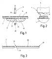
- Figures 1 to 3 show the process of separating one Bearing shell section of the band material and a related used punching tool.
- the reference number 2 is a from a roll of tape, not shown, continuously developed 2-component tape material called, by that by means of the punch 4 bearing shell sections are continuously separated.
- the punching tool 4 comprises an upper knife Stamp 6 and two lower blades 8, 10, between them the punch 6 to separate one Bearing shell section is passed.
- the Punch 6 is complementary to the cross-sectional contour of the Tape material 2 on the punch 6 facing Side trained. Before the tape is cut in Bearing shell sections is fed to the punching tool, will face the future sliding partner Top 12 an oil groove 14 extending in the longitudinal direction, introduced by milling, blasting or broaching.
- the oil groove 14 has a flat and parallel to the top extending groove bottom 16 and inclined to the top 12 extending groove flanks 18.
- the Stamp 6 thus has a complementary to Cross-sectional contour of the oil groove 14 formed projection 20 on.
- the two lower knives 8, 10 each have a transverse to the longitudinal or transport direction of the strip material 2 extending Cutting edge 22 or 24 on. These cutting edges 22, 24 are striving towards the punch 6 upwards educated.
- the punch 2 is down driven and between the cutting edges 22, 24 of the Lower knife 8, 10 moved through, so that when cutting the bearing shell section 26 a the width of the Stamp stamp corresponding waste piece 28 is generated.
- each Bearing shell section 26 is in the direction of movement Stamp 6 pulled down.
- 10 is achieved that none of the Top side 12 of the respective bearing shell section 26 opposite bottom 34 protruding cutting burr is formed, which would have to be removed or itself when inserting the bearing shell into a bearing can have a disastrous effect.
- the Stamp 6 is the waste piece 28 early sheared off, so that a formed in this case too Cutting burr does not protrude beyond the bottom 34.
- the Bearing shell sections 26 substantially semicircular bent. This takes place in a not shown Pre-bending stage shown in Figures 4 to 6 Press tool 40 instead. After bending to semicircular shape the bearing shell sections 26 in the in the figures 4 and 5 shown working position of the pressing tool preferably moved, in which the outside as well the dividing surfaces of the semicircular curved Bearing shell sections 26 are calibrated.
- the pressing tool 40 comprises a basic receiving body 42, which one of the outer shape of the bearing shell to be produced corresponding die 44 for the Bearing shell sections 26 carries.
- a hint Press upper part 46 shown is a press bridge 48 in Can be raised and lowered with respect to the die 44.
- the lower one End position is over to the base body 42 abutting stop blocks 50 defined or set.
- the press bridge 48 points against separating surfaces 52 Bearing shell sections 26 press bearing surfaces 54 that can be created on.
- the press bearing surfaces 54 go into one in the Bearing shell 26 engaging material guide section 56.
- the exact shape of the press bearing surfaces 54 in Transition area to the material guide section 56 corresponds the inner phase to be produced in the transition from the Partitions 52 to the inside 58 of the bearing shell 26.
- the respective Feed slope 66 is ramped outward current projection 74 of the tool flanks 60, 62 is formed, whose vertically returning ramp flank 76 is an axial one Stop surface 76 for the side tool flanks 60, 68 forms when closing the pressing tool.
- the axial Stop surface 76 partially abuts against it indicated depth stop 78, the base body is to be assigned.
- FIG. 8 On the left side of the press bridge 48 in FIG additional pressing tool stamp 80 is provided, which over the press bearing surface 54 in the form of a wedge-shaped Pressing or punching projection 82 protrudes.
- the Press tool stamp 80 or the wedge-shaped projection 82 serve to notch one shown in Figure 6 radial nose 84.
- a bearing shell section 26 is from the pre-bending stage to that in FIGS. 4 and 5 Machining position of the pressing tool 40 shown postponed.
- the upper press part 46 is in the direction lowered on the die 44. This strikes first the axial stop surface 76 against the depth stop 78 and thereby limits the movement of the side Tool flanks 60, 62 (see Figure 5).
- the upper press part 46 slides the adjusting means 68 via the respective delivery slope 66 of the side Tool flanks 60, 62 and move them across Lift direction towards each other until they reach the side Flanks 70, 72 of the bearing shell 26 with their contact section 86 and thus the width of the manufactured Define bearing shell.
- the final fixing of the width of the bearing shell 26 sets the press bridge 48 with its two press bearing surfaces 54 on the two separating surfaces 52 of the bearing shell 26 and compresses these separating surfaces 52 or the bearing shell 26.
- the outer side 88 of the bearing shell 26 Circumferential length calibrated and at the same time Partitions 52 brought to their final shape without that further parting surface processing, for example, by broaching the parting surfaces becomes necessary.
- the movement of the Press bridge 48 is countered by abutting the stops 50 the basic receiving body 42 of the pressing tool 40 stopped.
- the bearing shell 26 now has its final circumferential length on.
- the bearing shell material is used 26 displaced in the circumferential direction of the bearing shell. That this is not done in an uncontrolled manner by the Material guide section in the transition area of the Press bearing surfaces 54 to the inside of the bearing shell achieved and in that during the upsetting of the Partitions 52 the side tool flanks 60, 62 the Support bearing shell 26 and the ultimately desired Define bearing shell width precisely.
- the radial nose 84 When calibrating the outside 88 or the separating surfaces 52 through the upsetting process described above furthermore by the wedge-shaped punching projection 82 of the additional press die 80 the radial nose 84 into a radial recess 90 provided for this purpose notched in the die 44. If the radial nose 84 in this preferred way when calibrating the outside 88 and the separating surfaces 52 of the bearing shell 26, This means that the notched nose can be milled from the inside to be dispensed with, as this shape is already at Notching can be formed by the pressing tool.
Landscapes
- Engineering & Computer Science (AREA)
- General Engineering & Computer Science (AREA)
- Mechanical Engineering (AREA)
- Forging (AREA)
- Sliding-Contact Bearings (AREA)
- Polishing Bodies And Polishing Tools (AREA)
Claims (16)
- Procédé de fabrication de coquilles de coussinet plates, dans lequel des portions de coquilles de coussinet (26) sont découpées à partir d'une bande de matériau (2), ces portions sont cintrées de manière sensiblement semi-circulaire, et les faces externe et interne (88, 58) et les surfaces de séparation (52) de la coquille de coussinet ainsi formées sont calibrées, la face externe (88) ainsi que les surfaces de séparation (52) des portions de coquille de coussinet (26) cintrées selon une forme semi-circulaire étant calibrées par refoulement des surfaces de séparation (52) dans un outil de presse (40), caractérisé en ce que, pour découper les portions de coquille de coussinet (26) à partir de la bande de matériau (2), l'on utilise une lame inférieure (8, 10) présentant deux arêtes tranchantes (22, 24), entre lesquelles est guidé le poinçon de découpage (6).
- Procédé selon la revendication 1, caractérisé en ce que les arêtes tranchantes (22, 24) de la lame inférieure employée (8, 10) sont orientées vers le haut, en direction du poinçon de découpage (6), de sorte que lorsque l'on coupe au niveau de la face inférieure (34) de la bande de matériau (2) (vu dans le sens de découpage), il ne se forme aucune bavure de découpage en saillie de la face inférieure (34) de la bande de matériau.
- Procédé selon la revendication 1 ou 2, caractérisé en ce que lors du refoulement des surfaces de séparation (52), on refoule simultanément des chanfreins au niveau de la transition entre les surfaces de séparation (52) et la face interne des coquilles de coussinet.
- Procédé selon l'une quelconque des revendications précédentes, caractérisé en ce que, pendant l'opération de presse, les portions de coquille de coussinet cintrées (26) sont maintenues sur les deux côtés longitudinaux dans l'outil de cintrage.
- Procédé selon l'une quelconque des revendications précédentes, caractérisé en ce que lors du refoulement, un nez radial (84) est refoulé dans un évidement (90) de l'outil de presse (40).
- Procédé selon la revendication 5, caractérisé en ce que, après refoulement du nez (84), la coquille est pivotée par pression sur la surface de séparation (52) opposée au nez (84), de telle sorte que ledit nez se dégage de l'évidement (90) de l'outil de presse (40) et que la coquille peut être extraite après ouverture dudit outil de presse.
- Procédé selon l'une des revendications précédentes, caractérisé en ce que la rainure de graissage (14) est fraisée avant le découpage de la bande de matériau (2).
- Procédé selon la revendication 7, caractérisé en ce que les portions de coquilles de coussinet (26) sont découpées au moyen d'un poinçon de découpage (6) dont la forme correspond au contour de la section transversale de la bande de matériau (2) après fraisage de la rainure de graissage (14).
- Procédé selon l'une des revendications précédentes, caractérisé en ce que la lumière de coussinet est poinçonnée lors d'une étape ultérieure après calibrage de la face externe (88) et des surfaces de séparation (52) et avant calibrage de la face interne (58).
- Outil de découpage (4) et outil de presse (40) pour la fabrication de coquilles de coussinet plates, destinés à mettre en oeuvre le procédé selon une ou plusieurs des revendications précédentes, avec une matrice (44) affectant la forme périphérique de la coquille de coussinet à fabriquer et un pontage de presse (48) apte à être relevé et abaissé par rapport à la matrice (44) et doté d'une surface d'appui de presse (54) dont la forme correspond à celle de la surface de séparation (52) à fabriquer dans la zone de transition correspondante entre les surfaces de séparation (52) et la face interne (58) de la coquille de coussinet, ladite surface d'appui de presse pouvant être pressée contre les surfaces de séparation (52) d'une coquille de coussinet (26) insérée dans la matrice (44), et avec des presse-flancs latéraux (60,62) pour maintenir et définir la largeur de la coquille de coussinet lors de l'opération de presse, et avec un poinçon de découpage (6) et une lame inférieure, caractérisés en ce que la lame inférieure présente deux arêtes tranchantes (22, 24) entre lesquelles est guidé le poinçon de découpage (6).
- Outil de découpage et outil de presse selon la revendication 10, caractérisés en ce que les arêtes tranchantes (22, 24) de la,lame inférieure (8, 10) sont orientées vers le haut, en direction du poinçon de découpage (6), de sorte que lorsque l'on coupe au niveau de la face inférieure (34) de la bande de matériau (2) (vu dans le sens de découpage), il ne se forme aucune bavure de découpage en saillie de la face inférieure (34) de la bande de matériau.
- Outil de découpage et outil de presse selon la revendication 11, caractérisés en ce qu'au moins un des presse-flancs latéraux (60, 62) peut être amené en contact avec une extrémité latérale (70, 72) de la coquille de coussinet.
- Outil de découpage et outil de presse selon la revendication 10, 11 ou 12, caractérisés par un chanfrein de butée (66), au moyen duquel au moins un des presse-flancs latéraux (60, 62) peut être amené, perpendiculairement à la direction d'amenée du pontage de presse (48), en contact avec une extrémité latérale (70, 72) de la coquille de coussinet.
- Outil de découpage et outil de presse selon la revendication 13, caractérisés en ce que les presse-flancs latéraux (60, 62) sont précontraints par un ressort dans la direction d'amenée du pontage de presse (48) contre une partie supérieure (46) de la presse qui soulève et abaisse le pontage de presse.
- Outil de découpage et outil de presse selon l'une quelconque des revendications 10 à 14, caractérisés par un étage en amont avec un poinçon de formage semi-circulaire pour cintrer selon une forme semi-circulaire les portions de coquille de coussinet (26) découpées à partir de la bande de matériau (2).
- Outil de découpage et outil de presse selon la revendication 15, caractérisés par un dispositif de déplacement permettant de déplacer la portion de coquille de coussinet cintrée de l'étage préalable de cintrage vers l'étage de calibrage.
Applications Claiming Priority (3)
| Application Number | Priority Date | Filing Date | Title |
|---|---|---|---|
| DE19702445 | 1997-01-24 | ||
| DE19702445A DE19702445A1 (de) | 1997-01-24 | 1997-01-24 | Verfahren und Werkzeug zum Herstellen von Flachlagerschalen |
| PCT/EP1998/000347 WO1998032554A1 (fr) | 1997-01-24 | 1998-01-23 | Procede et outil de fabrication de coquilles de coussinet plates |
Publications (2)
| Publication Number | Publication Date |
|---|---|
| EP0954397A1 EP0954397A1 (fr) | 1999-11-10 |
| EP0954397B1 true EP0954397B1 (fr) | 2001-05-30 |
Family
ID=7818228
Family Applications (1)
| Application Number | Title | Priority Date | Filing Date |
|---|---|---|---|
| EP98906884A Expired - Lifetime EP0954397B1 (fr) | 1997-01-24 | 1998-01-23 | Procede et outil de fabrication de coquilles de coussinet plates |
Country Status (5)
| Country | Link |
|---|---|
| EP (1) | EP0954397B1 (fr) |
| AT (1) | ATE201619T1 (fr) |
| AU (1) | AU6293398A (fr) |
| DE (2) | DE19702445A1 (fr) |
| WO (1) | WO1998032554A1 (fr) |
Cited By (1)
| Publication number | Priority date | Publication date | Assignee | Title |
|---|---|---|---|---|
| CN109807567A (zh) * | 2019-03-19 | 2019-05-28 | 南昌航空大学 | 一种提高1d及以下小弯曲半径管弯头直端长度的方法 |
Families Citing this family (5)
| Publication number | Priority date | Publication date | Assignee | Title |
|---|---|---|---|---|
| JP3634277B2 (ja) * | 2001-03-07 | 2005-03-30 | 大同メタル工業株式会社 | すべり軸受の加工方法および加工装置 |
| AT412812B (de) * | 2002-08-27 | 2005-07-25 | Miba Gleitlager Gmbh | Gleitlagerschale |
| DE102005036689A1 (de) * | 2005-08-04 | 2007-02-08 | Federal-Mogul Wiesbaden Gmbh & Co. Kg | Lagerschale und Verfahren zu ihrer Herstellung |
| DE102015116004A1 (de) * | 2015-09-22 | 2017-03-23 | Alfing Kessler Sondermaschinen Gmbh | Kalibrierverfahren und Kalibriervorrichtung |
| CN120460569B (zh) * | 2025-06-16 | 2025-11-14 | 上海祥生贝克轴瓦有限公司 | 一种用于轴瓦加工的定位工装 |
Family Cites Families (11)
| Publication number | Priority date | Publication date | Assignee | Title |
|---|---|---|---|---|
| US2037838A (en) * | 1935-05-14 | 1936-04-21 | John H Van Uum | Method of making split tapered formed collars |
| US2648260A (en) * | 1948-08-21 | 1953-08-11 | Clevite Corp | Apparatus for manufacturing thin wall precision bearings |
| US3503109A (en) * | 1967-06-15 | 1970-03-31 | Clevite Corp | Method and apparatus for forming flange bearings |
| GB1394828A (en) * | 1971-07-21 | 1975-05-21 | Glacier Metal Co Ltd | Apparatus for manufacturing thin-walled half bearings |
| AT344486B (de) * | 1976-09-28 | 1978-07-25 | Miba Gleitlager Ag | Vorrichtung zum formen von lagerhalbschalen aus platinen |
| GB1594625A (en) * | 1977-07-27 | 1981-08-05 | Glacier Metal Co Ltd | Bearings |
| JPS5645239A (en) * | 1979-09-22 | 1981-04-24 | Taiho Kogyo Co Ltd | Method and device of arc-shaped forming |
| DE3805036C1 (fr) * | 1988-02-18 | 1989-07-06 | Glyco-Metall-Werke Daelen & Loos Gmbh, 6200 Wiesbaden, De | |
| US5199170A (en) * | 1988-04-07 | 1993-04-06 | Daido Metal Company Ltd. | Manufacturing method of half-split bearings |
| US4845817A (en) * | 1988-06-29 | 1989-07-11 | J. P. Industries, Inc. | Method of forming a half-round bearing |
| DE3908026C2 (de) * | 1989-03-11 | 1993-11-04 | Glyco Metall Werke | Verfahren zum herstellen eines profilierten gleitlagerelementes und vorrichtung zur durchfuehrung des verfahrens |
-
1997
- 1997-01-24 DE DE19702445A patent/DE19702445A1/de not_active Withdrawn
-
1998
- 1998-01-23 EP EP98906884A patent/EP0954397B1/fr not_active Expired - Lifetime
- 1998-01-23 WO PCT/EP1998/000347 patent/WO1998032554A1/fr not_active Ceased
- 1998-01-23 AT AT98906884T patent/ATE201619T1/de not_active IP Right Cessation
- 1998-01-23 AU AU62933/98A patent/AU6293398A/en not_active Abandoned
- 1998-01-23 DE DE59800790T patent/DE59800790D1/de not_active Expired - Fee Related
Cited By (1)
| Publication number | Priority date | Publication date | Assignee | Title |
|---|---|---|---|---|
| CN109807567A (zh) * | 2019-03-19 | 2019-05-28 | 南昌航空大学 | 一种提高1d及以下小弯曲半径管弯头直端长度的方法 |
Also Published As
| Publication number | Publication date |
|---|---|
| WO1998032554A1 (fr) | 1998-07-30 |
| ATE201619T1 (de) | 2001-06-15 |
| DE59800790D1 (de) | 2001-07-05 |
| DE19702445A1 (de) | 1998-07-30 |
| AU6293398A (en) | 1998-08-18 |
| EP0954397A1 (fr) | 1999-11-10 |
Similar Documents
| Publication | Publication Date | Title |
|---|---|---|
| DE102005021408B4 (de) | Nutenherstellungswerkzeug und ein Verfahren zur Herstellung eines zylindrischen Lagerelements | |
| EP1202825B1 (fr) | Procede et dispositif pour la formation d'un coin limite sur trois cotes a partir d'un materiau en forme de plaque et a surface plane | |
| EP1171259B1 (fr) | Procede et dispositif pour la division par rupture d'une piece | |
| EP1317974B1 (fr) | Procédé et machine pour fendre à plusieurs courses des pièces formés en plaque, en particulier des tôles | |
| DE102011089682B4 (de) | Matrize für eine Stanzvorrichtung, Stanzwerkzeug für eine Stanzvor-richtung mit einer solchen Matrize sowie Verfahren zum Heraus-schneiden von Werkstückteilen aus Werkstücken mit einer entspre-chenden Matrize | |
| DE69711696T2 (de) | Verfahren zum quereinpressen eines zylindrischen teils in ein rohrförmiges teil und entsprechende einheit aus zwei teilen | |
| EP0954397B1 (fr) | Procede et outil de fabrication de coquilles de coussinet plates | |
| EP2370214B1 (fr) | Procédé et dispositif de fabrication d'une cage d'un palier à roulement | |
| EP3366947B1 (fr) | Procédé de fabrication d'éclisses de chaîne peu polluantes | |
| CH665367A5 (en) | Eliminating material burr at edges of press-cut component - by at least one corrective cutting step on step-wise moving metal strip | |
| EP0275561A2 (fr) | Procédé et appareil de fabrication de pignons coniques | |
| EP2357048A1 (fr) | Procédé et dispositif destinés à influencer la surface de coupe et de fonction sur des pièces finies coupées en fines tranches | |
| DE3403668C2 (fr) | ||
| EP0954707B1 (fr) | Procede de fabrication de coquilles de coussinet plates | |
| DE102008009856B4 (de) | Verfahren zur Herstellung von Anlaufscheiben-Halbringen | |
| DE3112453C2 (de) | Verfahren zur Herstellung von Bimetallkontaktnieten | |
| WO2006072289A1 (fr) | Cames destinees a des arbres a cames fabriques | |
| DE4130521C2 (de) | Sägebandring und Verfahren zu seiner Herstellung | |
| DE4444857C1 (de) | Verfahren und Vorrichtung zur Herstellung mindestens einer Öffnung in der Wandung eines rohrartigen Teils | |
| CH709263B1 (de) | Werkzeug zum Herstellen eines Gewindes. | |
| DE3911441A1 (de) | Verfahren zur herstellung eines halbgeteilten lagers | |
| DE3435424A1 (de) | Pressstempel und verfahren zu seiner herstellung | |
| EP1470873B1 (fr) | Procédé de fabrication de fourchettes de changement de vitesse et fourchette pour boîtes de vitesses de véhicules automobiles | |
| DE60112120T2 (de) | Vorrichtung zum verbinden von duktilem material | |
| DE19519839A1 (de) | Vorrichtung zum Stanzschneiden von Metallbändern in Streifen |
Legal Events
| Date | Code | Title | Description |
|---|---|---|---|
| PUAI | Public reference made under article 153(3) epc to a published international application that has entered the european phase |
Free format text: ORIGINAL CODE: 0009012 |
|
| 17P | Request for examination filed |
Effective date: 19990713 |
|
| AK | Designated contracting states |
Kind code of ref document: A1 Designated state(s): AT DE FR GB IT |
|
| GRAG | Despatch of communication of intention to grant |
Free format text: ORIGINAL CODE: EPIDOS AGRA |
|
| 17Q | First examination report despatched |
Effective date: 20001005 |
|
| GRAG | Despatch of communication of intention to grant |
Free format text: ORIGINAL CODE: EPIDOS AGRA |
|
| GRAH | Despatch of communication of intention to grant a patent |
Free format text: ORIGINAL CODE: EPIDOS IGRA |
|
| GRAH | Despatch of communication of intention to grant a patent |
Free format text: ORIGINAL CODE: EPIDOS IGRA |
|
| GRAA | (expected) grant |
Free format text: ORIGINAL CODE: 0009210 |
|
| AK | Designated contracting states |
Kind code of ref document: B1 Designated state(s): AT DE FR GB IT |
|
| REF | Corresponds to: |
Ref document number: 201619 Country of ref document: AT Date of ref document: 20010615 Kind code of ref document: T |
|
| GBT | Gb: translation of ep patent filed (gb section 77(6)(a)/1977) |
Effective date: 20010530 |
|
| REF | Corresponds to: |
Ref document number: 59800790 Country of ref document: DE Date of ref document: 20010705 |
|
| ITF | It: translation for a ep patent filed | ||
| ET | Fr: translation filed | ||
| REG | Reference to a national code |
Ref country code: GB Ref legal event code: IF02 |
|
| PLBQ | Unpublished change to opponent data |
Free format text: ORIGINAL CODE: EPIDOS OPPO |
|
| PLBI | Opposition filed |
Free format text: ORIGINAL CODE: 0009260 |
|
| PLBF | Reply of patent proprietor to notice(s) of opposition |
Free format text: ORIGINAL CODE: EPIDOS OBSO |
|
| 26 | Opposition filed |
Opponent name: FEDERAL-MOGUL WIESBADEN GMBH & CO. KG Effective date: 20020228 Opponent name: WIELAND-WERKE AG Effective date: 20020228 |
|
| PLBF | Reply of patent proprietor to notice(s) of opposition |
Free format text: ORIGINAL CODE: EPIDOS OBSO |
|
| PLAY | Examination report in opposition despatched + time limit |
Free format text: ORIGINAL CODE: EPIDOSNORE2 |
|
| PLBC | Reply to examination report in opposition received |
Free format text: ORIGINAL CODE: EPIDOSNORE3 |
|
| PGFP | Annual fee paid to national office [announced via postgrant information from national office to epo] |
Ref country code: AT Payment date: 20050125 Year of fee payment: 8 |
|
| PGFP | Annual fee paid to national office [announced via postgrant information from national office to epo] |
Ref country code: GB Payment date: 20051219 Year of fee payment: 9 |
|
| PGFP | Annual fee paid to national office [announced via postgrant information from national office to epo] |
Ref country code: FR Payment date: 20060119 Year of fee payment: 9 |
|
| PG25 | Lapsed in a contracting state [announced via postgrant information from national office to epo] |
Ref country code: AT Free format text: LAPSE BECAUSE OF NON-PAYMENT OF DUE FEES Effective date: 20060123 |
|
| PGFP | Annual fee paid to national office [announced via postgrant information from national office to epo] |
Ref country code: IT Payment date: 20060131 Year of fee payment: 9 |
|
| PGFP | Annual fee paid to national office [announced via postgrant information from national office to epo] |
Ref country code: DE Payment date: 20060320 Year of fee payment: 9 |
|
| PLCK | Communication despatched that opposition was rejected |
Free format text: ORIGINAL CODE: EPIDOSNREJ1 |
|
| PLBN | Opposition rejected |
Free format text: ORIGINAL CODE: 0009273 |
|
| STAA | Information on the status of an ep patent application or granted ep patent |
Free format text: STATUS: OPPOSITION REJECTED |
|
| 27O | Opposition rejected |
Effective date: 20060330 |
|
| PG25 | Lapsed in a contracting state [announced via postgrant information from national office to epo] |
Ref country code: DE Free format text: LAPSE BECAUSE OF NON-PAYMENT OF DUE FEES Effective date: 20070801 |
|
| GBPC | Gb: european patent ceased through non-payment of renewal fee |
Effective date: 20070123 |
|
| REG | Reference to a national code |
Ref country code: FR Ref legal event code: ST Effective date: 20070930 |
|
| PG25 | Lapsed in a contracting state [announced via postgrant information from national office to epo] |
Ref country code: GB Free format text: LAPSE BECAUSE OF NON-PAYMENT OF DUE FEES Effective date: 20070123 |
|
| PG25 | Lapsed in a contracting state [announced via postgrant information from national office to epo] |
Ref country code: FR Free format text: LAPSE BECAUSE OF NON-PAYMENT OF DUE FEES Effective date: 20070131 |
|
| PLAB | Opposition data, opponent's data or that of the opponent's representative modified |
Free format text: ORIGINAL CODE: 0009299OPPO |
|
| PG25 | Lapsed in a contracting state [announced via postgrant information from national office to epo] |
Ref country code: IT Free format text: LAPSE BECAUSE OF NON-PAYMENT OF DUE FEES Effective date: 20070123 |