EP0954504B1 - Vorrichtung zum umlenken von schienengeführten transportkörpern von einem schienenstrang auf einen anderen - Google Patents
Vorrichtung zum umlenken von schienengeführten transportkörpern von einem schienenstrang auf einen anderen Download PDFInfo
- Publication number
- EP0954504B1 EP0954504B1 EP97944678A EP97944678A EP0954504B1 EP 0954504 B1 EP0954504 B1 EP 0954504B1 EP 97944678 A EP97944678 A EP 97944678A EP 97944678 A EP97944678 A EP 97944678A EP 0954504 B1 EP0954504 B1 EP 0954504B1
- Authority
- EP
- European Patent Office
- Prior art keywords
- rail track
- rail
- conveying element
- transporter
- additional
- Prior art date
- Legal status (The legal status is an assumption and is not a legal conclusion. Google has not performed a legal analysis and makes no representation as to the accuracy of the status listed.)
- Expired - Lifetime
Links
- 230000008878 coupling Effects 0.000 claims abstract description 20
- 238000010168 coupling process Methods 0.000 claims abstract description 20
- 238000005859 coupling reaction Methods 0.000 claims abstract description 20
- 230000007704 transition Effects 0.000 claims description 38
- 241000723353 Chrysanthemum Species 0.000 claims 1
- 235000005633 Chrysanthemum balsamita Nutrition 0.000 claims 1
- 230000014759 maintenance of location Effects 0.000 description 6
- 238000011144 upstream manufacturing Methods 0.000 description 5
- 235000004443 Ricinus communis Nutrition 0.000 description 2
- 230000003993 interaction Effects 0.000 description 2
- 210000002105 tongue Anatomy 0.000 description 2
- 241000792859 Enema Species 0.000 description 1
- 208000012886 Vertigo Diseases 0.000 description 1
- 239000007822 coupling agent Substances 0.000 description 1
- 238000011143 downstream manufacturing Methods 0.000 description 1
- 239000007920 enema Substances 0.000 description 1
- 229940095399 enema Drugs 0.000 description 1
- 230000005281 excited state Effects 0.000 description 1
- 239000003302 ferromagnetic material Substances 0.000 description 1
- 230000001360 synchronised effect Effects 0.000 description 1
- 230000002123 temporal effect Effects 0.000 description 1
- 230000007306 turnover Effects 0.000 description 1
Images




Classifications
-
- B—PERFORMING OPERATIONS; TRANSPORTING
- B65—CONVEYING; PACKING; STORING; HANDLING THIN OR FILAMENTARY MATERIAL
- B65H—HANDLING THIN OR FILAMENTARY MATERIAL, e.g. SHEETS, WEBS, CABLES
- B65H29/00—Delivering or advancing articles from machines; Advancing articles to or into piles
- B65H29/02—Delivering or advancing articles from machines; Advancing articles to or into piles by mechanical grippers engaging the leading edge only of the articles
- B65H29/04—Delivering or advancing articles from machines; Advancing articles to or into piles by mechanical grippers engaging the leading edge only of the articles the grippers being carried by endless chains or bands
-
- B—PERFORMING OPERATIONS; TRANSPORTING
- B65—CONVEYING; PACKING; STORING; HANDLING THIN OR FILAMENTARY MATERIAL
- B65H—HANDLING THIN OR FILAMENTARY MATERIAL, e.g. SHEETS, WEBS, CABLES
- B65H29/00—Delivering or advancing articles from machines; Advancing articles to or into piles
- B65H29/58—Article switches or diverters
- B65H29/60—Article switches or diverters diverting the stream into alternative paths
-
- B—PERFORMING OPERATIONS; TRANSPORTING
- B65—CONVEYING; PACKING; STORING; HANDLING THIN OR FILAMENTARY MATERIAL
- B65H—HANDLING THIN OR FILAMENTARY MATERIAL, e.g. SHEETS, WEBS, CABLES
- B65H29/00—Delivering or advancing articles from machines; Advancing articles to or into piles
- B65H29/003—Delivering or advancing articles from machines; Advancing articles to or into piles by grippers
-
- B—PERFORMING OPERATIONS; TRANSPORTING
- B65—CONVEYING; PACKING; STORING; HANDLING THIN OR FILAMENTARY MATERIAL
- B65H—HANDLING THIN OR FILAMENTARY MATERIAL, e.g. SHEETS, WEBS, CABLES
- B65H2405/00—Parts for holding the handled material
- B65H2405/50—Gripping means
- B65H2405/55—Rail guided gripping means running in closed loop, e.g. without permanent interconnecting means
Definitions
- the present invention relates to a device for Deflection of rail-guided, independent of each other Transport bodies from the guide area of a first rail track to the management area of one with respect to the first Rail track arranged second at an angle Rail track.
- EP-A-0 918 720 which is based on priority and is based on Swiss Patent Application No. 1996 1818/96 a device for feeding printed matter to processing stations. It has a rail system on the independent, with Carriages equipped with clamps for transporting the printed matter are led. A trunk conveyor line of the rail system is via controlled switches to the processing stations leading supply routes connected. On the feed lines connect return lines that again flow into the main conveyor via switches, to put the brackets back into this. In devices of this kind with independent carriages running along large parts of the rail system are freely movable, the distance between successive carriages can be strong vary. So it is possible that consecutive cars abut each other.
- CH 382 768 A discloses a device for deflecting of rail-guided, independent from each other Transport bodies according to the preamble of claim 1.
- the inventive Solution allows omitting one in the radial direction seen external guide for the support body in the Transition area from the guide area of the first rail track to the guide area of the second rail track.
- a switch tongue can be used be waived, all related to problems caused by switching switch blades.
- the transport body in the transition area actively promoted, so they have to redirect a precisely defined speed and run at this in the second track. This sets advantageous Requirements for the further downstream Processing of the transport body.
- the coupling means for coupling the transport body the conveying element of the deflection device can Transport bodies themselves can be arranged. advantageously, are the coupling means as stated in claim 3, but assigned to the deflection device. This makes possible an extremely simple form of training the transport body.
- a particularly preferred embodiment of the invention Device is defined in claim 4.
- Form the deflection device and the coupling means a clamping device for the transport body can be in the transition area the rail-side guidance of the transport bodies partially or even completely canceled.
- a particularly preferred embodiment of the invention Device is defined in claim 5. It enables an extremely simple design of the transport body and coupling agents.
- a form of training that is particularly simple to set up and operate the device according to the invention is in the claim 6 specified.
- FIG. 7 Another particularly preferred embodiment of the inventive Device is defined in claim 7.
- a circular segment-like movement path of the transport body in the transition area a circular disc or wheel-shaped design of the support element.
- Apparatus according to claim 8 enables training the device with a rectilinear section. If drive links are provided, take the transport body a defined mutual in the area of the device Location one thing, especially when merging two strands to one strand brings advantages.
- Device according to claim 9 can be from each other independent transport bodies at the desired time are processed. This allows in particular when merging two strands collisions of Prevent transport objects occurring on both strands.
- a particularly preferred embodiment of the invention Device for feeding on a strand Transport bodies to two strands is required 10 defined.
- a particularly economical form of training the device according to the invention is defined in claim 13. It requires a small number of different ones Parts.
- a particularly preferred embodiment of the invention Device is specified in claim 14.
- internal rotor can be made particularly small.
- a leadership element ensures an optimal enema of the Transport body in the guide area of the downstream located rail track.
- the particularly preferred embodiment of the invention Device according to claim 15 enables the individual Processing of flat products, in particular Printed products. There can be different Sources of products for further processing merged and stranded products be split up for further processing.
- Another particularly preferred embodiment of the inventive Device according to claim 16 allows Preparation of products to meet the needs of the following Processing stations.
- the particularly preferred form of training of the transport body according to claim 17 allows simple training of single-shot units and an optimal interaction between this and the transport bodies.
- the device shown in FIGS. 1 and 2 has one Rail system with rails 10 which are C-shaped in cross section on in which are independent of each other, as internal runners trained transport body 12 guided freely movable are.
- the second and third rail tracks 16, 18 are arranged symmetrically with respect to the first rail track 14 and each make an angle ⁇ with it or ⁇ 'of 135 °. This angle can also be larger or be smaller.
- From the guide area 14 'of the first Rail track 14 extends to the guide area 16 ' of the second rail track 16 a first transition area 20 with an arcuate bend 22.
- the guide areas 14 ', 16' of the two rail tracks concerned 14, 16 close the bend in the tangential direction 22 on.
- a corresponding second transition region 20 'with an opposite bend 22 extends from the first Rail line 14 to the third rail line 18. Die with respect to the bend 22 of the first transition region 20 outer side edge 24 of the second rail track assigned rail, ends at the third rail track 18. The outer side flank also ends 24 of the rail 10 of the third rail track 18 in the second track 16.
- 20 'thus take over the second and third Rail track 16, 18 radially outside on the transport body 12 no management function.
- first deflection device 26 With regard to the bend 22 of the first transition region 20 is on the inner side of a first deflection device 26 with a drive that rotates in the transport direction T, conveyor element designed as a conveyor disk 28 30 arranged. Regarding a center plane of the first Rail section 14 is a mirror image of the first deflection device 26 there is a second deflection device 26 ′, which is assigned to the second transition region 20 '. The two deflection devices 26, 26 'are mirror images educated.
- the conveyor disc 28 is at the lower end of one a frame 32 mounted shaft 34 attached.
- the axis 34 'of the shaft 34 coincides with the center of the circular Bend 22 of the relevant transition region 20 together.
- the Transport body 12 with a transport body part 36 over the rail 10 in front and have on the transport body part 36 in Transport direction T seen on both sides tongue-like projections 38 on.
- the one below, facing away from the rail 10 The surface of these projections 38 form a shoulder 40, which is designed to adhere to the overhead surface create the conveyor disc 28; this therefore constitutes Support element 28 'for the transport body 12.
- the size of the lamellar wheel 42 is selected such that it is in a recess 44 of the Rail system in the transition area 20 and adjoining this End or start sections 46, 46 'of engages first and second rail track 14, 16 in order with shoulders 40 'on top of the transport body 12 co.
- the disks 42 ′ of the disk wheel 42 are characterized by cuts in the radial direction in an umbrella-like curved, forming the lamellar wheel 42 Disc made of a resilient, ferromagnetic Material formed.
- the clamping link 50 also spends the remaining slats 42 'in the clamping position, but can this to one in the other transition area 20 or 20 'located transport body 12 do not act, since this is outside the effective range of the Clamping scenes 50 influenced slats 42 '.
- the Lamellar wheel 42 with the associated electromagnet 48 thus forms a controlled, cooperating with the support member 28 ' Clamping element 51 for those to be deflected Transport body 12.
- a seat sits on the shaft 34 of each deflection device 26, 26 ' Gear 52. These equal-sized gears 52 mesh with one another, around the two deflection devices 26, 26 'synchronously and drive in the opposite direction. Sits on the shaft 34 of the first deflection device 26 further a sprocket 54 connected to a drive motor Chain drive 54 'for driving the deflection device 26, 26 '.
- the lamellar wheel 42 and the controlled electromagnet 48 thus form a coupling means 56 to the concerned Rail section 16 or 18 to be supplied transport body 12 to the conveyor element 30 of the rail track in question 16, 18 associated deflection device 26 or 26 ' to couple.
- Seen in the direction of transport T is the deflection 26, 26 'upstream of a sensor 58. This is one of them determined to recognize an incoming transport body 12 and, if necessary, a coding attached to it read.
- the output signals from sensor 58 become one Not shown control device supplied, which Electromagnets 48 controls the transport body 12 to supply the desired second or third rail track 16, 18.
- a swivel castor 60 is freely rotatable, around the transport bodies deflected in one of the two directions 12 when entering the relevant rail track 16, 18 to lead radially outside.
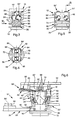
- the transport body 12 shown in FIGS. 3 to 5 has one in a running channel 62 formed by the rail 10 arranged transport body part 36 'in which the balls 64 of two seen in the transport direction T one behind the other arranged ball triplets 64 'freely rotatable are.
- the transport body part 36' has a Y-like trained cage 66, with those in the arms this cage arranged balls 64 touch each other and can roll on each other.
- Each ball 64 of a triplet 64 ' is on its, projecting beyond the transport body 12 Part, arranged on a on the rail 10 Ball race pair 68 performed.
- a pair of balls is 68 in each case at the end region of each side flank 24 of the rail 10 and the third on the two side flanks 24 connecting Rail web 10 'arranged.
- the structure of the rail 10 and of the transport body part 36 'arranged in the running channel 62 with the ball triplets 64 'and their interaction with the rail 10 is described in detail in EP-A-0 387 318.
- the one protruding from the running channel 62 with the transport body part 36 'integrally formed transport body part 36 laterally has the projections described above 38 with the shoulders 40 on.
- convex Drive surfaces 70 formed On the rail 10 and the side of the projections facing the transport body part 36 ' 38 are on the transport body part 36 lateral, convex Drive surfaces 70 formed, their purpose and mode of operation is described below.
- a support element thereon 72 attached, for example, a bracket for the Transport of printed matter may be appropriate.
- Fig. 6 partially shows that shown in Figs. 1 and 2 second deflection device 26 'when deflecting a transport body 12 in the second transition region 20 ', the Transport body 12 in the guide area 18 'of the third Rail track 18 is introduced.
- the transport body 12 lies with its shoulder 40 on the conveyor disc 28 and on the shoulder 40 'by means of the clamping link 50 Lamels 42 'of the lamellar wheel held in the clamping position 42 on.
- the transition area 20 ' are the web 10' Rail 10 and that of the radially inner, the guide element 24 'forming side flank 24 facing Balls 64 guided on corresponding ball race pairs 68, whereas the radially outer balls 64 are free and only after entering the management area 18 'of the third rail track 18 are guided again.
- the steering roller acting on the transport body part 36 ' 60 supports the entry of these balls 64 onto this one assigned pair of balls 68.
- the slats 42 ' give the transport body 12 free and run off the clamping link 50, as soon as the transport body 12 is guided in the guide area 18 ' is.
- the steering wheel 76 is determined with its outer surface 76 'with a circular cylindrical To interact surface surface 72 'of the support member 72.
- the speed of the steering wheel 76 is greater than the speed the conveyor disc 28 and the lamellar wheel 42 the support member 72 against the bend 22 with respect to the Transport body 12 rotated.
- Speed of the control wheel 76 has the consequence that the support element 72 is rotated in the direction of the bend 22. in the shown example, the speeds are so on each other matched that the support member 72 in the bend 22 the Maintains orientation that it is in the first rail track 14 when entering the transition area 20 '.
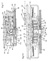
- deflection devices 26 shown in FIGS. 9 and 10, 26 ' are constructed essentially the same as those in FIGS 1 and 2 deflection devices shown. Parts of the in 9 and 10 deflection devices 26, 26 ', who have the same training and perform the same function as in the embodiment shown in FIGS. 1 and 2, are provided with the same reference numerals; it will continue to the appropriate description points referenced above.
- Successive links in the conveyor chain 82 are alternate arranged below or above, where the lower links each form a support link 86, which is intended as a support element 28 'with the Shoulders 40 of the transport body 12 cooperate.
- the to a support member 86 adjacent links form driving links 86 ', the projections 38 between them Pick up the transport body 12 so that it can be carried along.
- the first and third rail track 14, 18 is one each upstream of the relevant single-ended unit 88 Associated with sensor 58, the incoming transport body 12 recognizes and corresponding signals to a not shown Control unit for controlling the single-stroke units 88 and of the slats 42 'of the slat wheels 42 in the clamping position spending magnet 48 emits.
- the clamping links 50 are direct to the electromagnet 48 upstream. They spend every move past her Slat 42 'in the clamping position. When the electromagnet is de-energized 48, however, the slats 42 'move in the rest position before moving onto a transport body 12 can act by means of the other deflection device 26 or 26 'is deflected.
- FIGS. 11 to 14 The structure and mode of operation of the single-ended units 88 can be seen from FIGS. 11 to 14.
- Each of the single-shot units 88 points on both sides of the rail track in question 14 or 18 forming rail 10 a truncated cone Drive wheel 90 with a polygonal circumference.
- the drive wheels 90 sit on another frame 92 mounted shafts 94, which in turn over each other intermeshing gear wheels 96 of the same diameter are connected to the drive.
- Sits on one of these shafts 94 further rotatably a sprocket 98 around which a chain 99th is guided, on the other hand, to a on a coupling element 100 seated further sprocket 98 'runs.
- the Coupling element 100 is part of a coupling 102 that is on a shaft 104 is arranged on which the relevant deflection wheel 84 is attached.
- the clutch 102 gets from the Control device commands, on the one hand, around the shaft 94 Driving the single-ended unit 88 to the shaft 104 couple and on the other hand to release this clutch and the Single-ended unit 88 by coupling the coupling element 100 to stop and hold a non-rotatable element 100 '.
- the further frame 92 is further on both sides of the rail 10 a two-armed retaining lever 106 is rotatably supported.
- the two are arranged approximately parallel to the rail 10 Retaining levers 106 point at their T in the transport direction seen downstream lever end a retaining lug 108 and a freely rotatably mounted control roller 110, from below into a recess 112 in the drive wheels 90 intervention; forms the lateral surface of the recess 112 a control link 114 for the control rollers 110.
- Am der Control roller 110 and the retaining lug 108 facing away from the end the retaining levers 106 are each attached to a spring 116, the other attached to the other frame 92 to bias the retainer levers 106 in the retainer position.
- the Control link 114 is a substantially square-round Form, with the control rollers 110 in the retention position each in a rounded "corner area" of the control link 114 are arranged, as shown in FIGS. 12 and 13 demonstrate.
- the control links 114 control the retaining lever 106 initially against the force of the springs 116 in a release position and towards the end of this Rotational movement back to the restraint position.
- the Release position of the retaining lever 106 and the corresponding The rotational position of the drive wheels 84 is in FIG. 14 and 15 are shown.
- the outer polygonal, cylindrical outer surface 90 'of Drive wheels 90 are shaped such that their distance from the Axis of rotation of shaft 94 at the "corners" of the control link 114 lowest and in the middle of the control link 114 is largest between two "corners".
- the retention lever 106 is in the retention position and lies a transport body 112 with its projection 38 to the Retaining lugs 108, the drive wheels 90 are also located with its outer surface 90 'on the drive surfaces 70 of the Transport body part 36.
- the shape of the convex drive surfaces 70 and the shape of the convex surface 90 'of the drive wheels 90 are on top of each other matched that when turning the drive wheels 90 whose Shell surfaces 90 'roll on the drive surfaces 70 in such a way that the transport body 12 in the transport direction T is accelerated.
- the increase in distance serves this purpose of the outer surface 90 'to the shaft 94.
- Transport body 12 is recognized by sensor 58.
- This transport body 12 is the third rail track 18 feed, is seen in the transport direction T of second deflection device 26 'arranged on the left Electromagnet 48 excited.
- This will make each slats 42 'moved past it in the clamping position, which means that the one with its in the direction of transport T seen left shoulder 40 on the continuously driven conveyor disc 28 for support coming transport body 12, between that and the lamellar wheel 42 is pinched. Since the electromagnets 48 the deflection devices 26, 26 'are driven in opposite directions the second deflection device 26 ' held transport body 12 unhindered on the first Move deflection device 26 past.
- An incoming transport body 12 is the second rail track 16 to be fed in the direction of transport T seen on the right-hand deflection device 26 Electromagnet 48 excited and at the same time that of the second Deflection device 26 'associated electromagnet 48 de-energized, which has the consequence that the transport body 12th between the conveyor disc 28 and the lamellar wheel 42 of the first deflection device 26 clamped and by the first transition area 20 through the guide area 16 'of the second rail rod is fed.
- the transport body 12 on the radially inner Side to the relevant deflection device 26 or 26 'are coupled the transport body 12 with any distance can be processed consecutively. This even if they are in the area of the first rail track 14 lie against each other.
- the device according to the invention are on two rail tracks 14 and 18 resulting transport body 12 a single, the second rail track 16 fed.
- One on the first or third rail track 14, 18 arriving Transport body 12 is by means of the relevant sensor 58 recognized. Decides based on the signals from the sensors 58 the control device, which single-ended unit 88 for Releasing and accelerating a transport body 12 is released.
- the single-ended unit assigned to the third rail track 88 stopped, causing the person concerned Transport body 12 to those in the retention position Retaining levers 106 abuts and not in the effective range the continuously rotating conveyor chain 82 can reach.
- the single-stroke unit assigned to the first rail track 14 88 is temporarily driving the idler wheel 84 and thus the relevant, also continuously driven Conveyor chain 82 and first deflection device 26 coupled.
- Your restraint levers 106 were due to the rotation the drive wheels 90 pivoted in the release position and that located between the drive wheels 90 Transport body 12 is accelerated in the transport direction T.
- the release of the single-ended unit 88 is with the movement the conveyor chain 82 synchronized so that the released and accelerated transport body 12 between two drive links 86 'on a support member 86 for Facility is coming.
- Support members 86 each with a transport body 12 occupied, whereas the corresponding support members 86 of the conveyor chain 82 associated with third rail track 18 are free. In this way, on the one hand, it prevents that two transport body 12 when the Rail tracks 14, 18 run onto each other and on the other hand the order of feeding the transport body 12 controlled to the second rail track 16.
- the slats 42 'concerned are excited by means of the corresponding electromagnet 48 in the clamping position held until the respective transport body 12 in Guide area 16 'of the second rail track 16 is located.
- the electromagnet which is not energized, leaves the the associated clamping link 50 previously in the clamping position move the held slats 42 'back into their rest position, before moving one from the other deflector influence held transport body 12 can.
- the described principle of deflecting transport objects 12 from a first rail track 14 or 18 a second rail track 16 or 18 can also be used, if two rail tracks, e.g. the rail tracks 14 and 16, aligned with each other, i.e. if the angle ⁇ between these rail tracks is 180 °. It can only one deflection device 26 may be provided, either as shown in the figures on the inside of the transition area having a bend or but with a straight transition area on the outer side of the two aligned rail tracks is arranged. In the latter case it is Conveying element 30 is formed as shown in Fig. 9, wherein the coupling means along a closed orbit, which correspond to the course of the conveying element 30, has an elongated section.
Landscapes
- Engineering & Computer Science (AREA)
- Mechanical Engineering (AREA)
- Framework For Endless Conveyors (AREA)
- Intermediate Stations On Conveyors (AREA)
- Platform Screen Doors And Railroad Systems (AREA)
- Replacing, Conveying, And Pick-Finding For Filamentary Materials (AREA)
- Replacement Of Web Rolls (AREA)
- Branching, Merging, And Special Transfer Between Conveyors (AREA)
- Specific Conveyance Elements (AREA)
- Chutes (AREA)
- Chain Conveyers (AREA)
Applications Claiming Priority (3)
| Application Number | Priority Date | Filing Date | Title |
|---|---|---|---|
| CH6597 | 1997-01-15 | ||
| CH6597 | 1997-01-15 | ||
| PCT/CH1997/000409 WO1998031623A1 (de) | 1997-01-15 | 1997-10-28 | Vorrichtung zum umlenken von schienengeführten transportkörpern von einem schienenstrang auf einen anderen |
Publications (2)
| Publication Number | Publication Date |
|---|---|
| EP0954504A1 EP0954504A1 (de) | 1999-11-10 |
| EP0954504B1 true EP0954504B1 (de) | 2002-01-16 |
Family
ID=4178506
Family Applications (1)
| Application Number | Title | Priority Date | Filing Date |
|---|---|---|---|
| EP97944678A Expired - Lifetime EP0954504B1 (de) | 1997-01-15 | 1997-10-28 | Vorrichtung zum umlenken von schienengeführten transportkörpern von einem schienenstrang auf einen anderen |
Country Status (13)
| Country | Link |
|---|---|
| US (1) | US6364092B1 (da) |
| EP (1) | EP0954504B1 (da) |
| JP (1) | JP2001508724A (da) |
| KR (1) | KR20000070166A (da) |
| AT (1) | ATE212002T1 (da) |
| AU (1) | AU722198B2 (da) |
| BR (1) | BR9714526A (da) |
| CA (1) | CA2277167A1 (da) |
| DE (2) | DE59706032D1 (da) |
| DK (1) | DK0954504T3 (da) |
| ES (1) | ES2166562T3 (da) |
| RU (1) | RU2179142C2 (da) |
| WO (1) | WO1998031623A1 (da) |
Families Citing this family (2)
| Publication number | Priority date | Publication date | Assignee | Title |
|---|---|---|---|---|
| CN106809634B (zh) * | 2017-03-01 | 2022-11-15 | 广州明森科技股份有限公司 | 一种智能卡过渡旋转装置 |
| DE102020125077A1 (de) * | 2020-09-25 | 2022-03-31 | Deutsche Post Ag | Vorrichtung zur Ausrichtung von Packstücken |
Family Cites Families (11)
| Publication number | Priority date | Publication date | Assignee | Title |
|---|---|---|---|---|
| US2363189A (en) * | 1941-10-18 | 1944-11-21 | Pneumatic Scale Corp | Container separating apparatus |
| US2770349A (en) * | 1952-03-21 | 1956-11-13 | American Can Co | Conveyor mechanism for dividing single line of articles into double line |
| US2835375A (en) * | 1955-11-16 | 1958-05-20 | King Sales & Engineering Co | Distributor mechanism with carrier plates |
| US2843254A (en) * | 1957-07-29 | 1958-07-15 | Diamond Gardner Corp | Sorting and orienting |
| US3098552A (en) * | 1959-08-05 | 1963-07-23 | American Can Co | Can divider |
| DE2401587A1 (de) * | 1974-01-14 | 1975-07-17 | Bauer Eberhard | Vorrichtung zur verteilung von auf einer bahn zugefuehrten gegenstaenden auf mehrere bahnen |
| CH596061A5 (da) * | 1976-01-16 | 1978-02-28 | Ferag Ag | |
| CH659053A5 (de) * | 1982-11-02 | 1986-12-31 | Grapha Holding Ag | Vorrichtung zum abzweigen von im schuppenstrom angelieferten produkten. |
| US4638906A (en) * | 1985-11-19 | 1987-01-27 | Harris Graphics Corporation | Conveyor assembly |
| US5007624A (en) | 1989-05-25 | 1991-04-16 | Am International Incorporated | Sheet material handling apparatus and method |
| IT1240127B (it) * | 1990-03-07 | 1993-11-27 | Cavanna Spa | Dispositivo per convogliare articoli, particolarmente per impianti automatici di confezionamento. |
-
1997
- 1997-10-28 JP JP53347498A patent/JP2001508724A/ja active Pending
- 1997-10-28 DE DE59706032T patent/DE59706032D1/de not_active Expired - Lifetime
- 1997-10-28 KR KR1019997006392A patent/KR20000070166A/ko not_active Ceased
- 1997-10-28 CA CA002277167A patent/CA2277167A1/en not_active Abandoned
- 1997-10-28 WO PCT/CH1997/000409 patent/WO1998031623A1/de not_active Ceased
- 1997-10-28 AU AU46135/97A patent/AU722198B2/en not_active Ceased
- 1997-10-28 RU RU99118020/12A patent/RU2179142C2/ru not_active IP Right Cessation
- 1997-10-28 EP EP97944678A patent/EP0954504B1/de not_active Expired - Lifetime
- 1997-10-28 BR BR9714526-2A patent/BR9714526A/pt not_active Application Discontinuation
- 1997-10-28 AT AT97944678T patent/ATE212002T1/de not_active IP Right Cessation
- 1997-10-28 DK DK97944678T patent/DK0954504T3/da not_active Application Discontinuation
- 1997-10-28 ES ES97944678T patent/ES2166562T3/es not_active Expired - Lifetime
- 1997-11-03 DE DE19748498A patent/DE19748498A1/de not_active Withdrawn
-
1999
- 1999-07-01 US US09/346,091 patent/US6364092B1/en not_active Expired - Lifetime
Also Published As
| Publication number | Publication date |
|---|---|
| CA2277167A1 (en) | 1998-07-23 |
| JP2001508724A (ja) | 2001-07-03 |
| ATE212002T1 (de) | 2002-02-15 |
| DE59706032D1 (de) | 2002-02-21 |
| AU4613597A (en) | 1998-08-07 |
| EP0954504A1 (de) | 1999-11-10 |
| AU722198B2 (en) | 2000-07-27 |
| DE19748498A1 (de) | 1998-07-16 |
| ES2166562T3 (es) | 2002-04-16 |
| DK0954504T3 (da) | 2002-04-02 |
| WO1998031623A1 (de) | 1998-07-23 |
| KR20000070166A (ko) | 2000-11-25 |
| US6364092B1 (en) | 2002-04-02 |
| RU2179142C2 (ru) | 2002-02-10 |
| BR9714526A (pt) | 2000-05-02 |
Similar Documents
| Publication | Publication Date | Title |
|---|---|---|
| EP0930248B1 (de) | Vorrichtung zum Sortieren von Stückgütern | |
| DE60208232T2 (de) | Fördersystem mit umleitlaufschienennetz | |
| DE19609633B4 (de) | Vorrichtung zum Fördern von Gegenständen | |
| EP0633212B1 (de) | Endlos umlaufende Stückgut-Transportvorrichtung mit individuellen Transportorganen | |
| DE69720125T2 (de) | Transporteinheit für Produkte | |
| EP1042196B1 (de) | Fördereinrichtung und entsprechendes transportmittel | |
| EP3501878A1 (de) | Transporteinrichtung in form eines langstatorlinearmotors | |
| EP3225572B1 (de) | Fördervorrichtung zur beförderung von hängenden gegenständen | |
| EP0249839B1 (de) | Seilförderanlage, insbesondere Seilschwebebahn | |
| EP2428471B1 (de) | Fördersystem | |
| DE69611740T2 (de) | Vorrichtung zum Sortieren von Produkten | |
| EP1258439A1 (de) | Anlage zum Transport von Objekten auf Förderbahnen mittels einer förderkammangetriebenen Transportrolle | |
| EP0944544B1 (de) | Verfahren und anordnung zum fördern von individuell gehaltenen produkten | |
| DE4345160C2 (de) | Vorrichtung zur Richtungsumkehr von flachen Sendungen | |
| DE19724194C2 (de) | Gefällerollenbahn mit gebremsten Tragrollen und Verfahren zu deren Betrieb | |
| DE3918006C2 (da) | ||
| DE2742438C2 (de) | Einrichtung zum Verändern der Transportgeschwindigkeit von Stückgütern | |
| EP2100839A1 (de) | Fördervorrichtung für die Uebernahme und Weitergabe von Druckprodukten | |
| EP0954504A1 (de) | Vorrichtung zum umlenken von schienengeführten transportkörpern von einem schienenstrang auf einen anderen | |
| WO2005115892A1 (de) | Vorrichtung zur richtungsumkehr von flachen sendungen | |
| DE19681063C1 (de) | Fördereinrichtung | |
| DE10044612A1 (de) | Kippstation für Stückgutförderer | |
| EP0139287A2 (de) | Stetigförderer | |
| EP3142914B1 (de) | Transportvorrichtung zum transport von gütern | |
| DE102004026138B3 (de) | Vorrichtung zur Geschwindigkeitsänderung laufender Druckerzeugnisse |
Legal Events
| Date | Code | Title | Description |
|---|---|---|---|
| PUAI | Public reference made under article 153(3) epc to a published international application that has entered the european phase |
Free format text: ORIGINAL CODE: 0009012 |
|
| 17P | Request for examination filed |
Effective date: 19990615 |
|
| AK | Designated contracting states |
Kind code of ref document: A1 Designated state(s): AT BE CH DE DK ES FI FR GB IT LI NL SE |
|
| GRAG | Despatch of communication of intention to grant |
Free format text: ORIGINAL CODE: EPIDOS AGRA |
|
| 17Q | First examination report despatched |
Effective date: 20001228 |
|
| GRAG | Despatch of communication of intention to grant |
Free format text: ORIGINAL CODE: EPIDOS AGRA |
|
| GRAG | Despatch of communication of intention to grant |
Free format text: ORIGINAL CODE: EPIDOS AGRA |
|
| GRAH | Despatch of communication of intention to grant a patent |
Free format text: ORIGINAL CODE: EPIDOS IGRA |
|
| GRAH | Despatch of communication of intention to grant a patent |
Free format text: ORIGINAL CODE: EPIDOS IGRA |
|
| GRAA | (expected) grant |
Free format text: ORIGINAL CODE: 0009210 |
|
| REG | Reference to a national code |
Ref country code: GB Ref legal event code: IF02 |
|
| AK | Designated contracting states |
Kind code of ref document: B1 Designated state(s): AT BE CH DE DK ES FI FR GB IT LI NL SE |
|
| REF | Corresponds to: |
Ref document number: 212002 Country of ref document: AT Date of ref document: 20020215 Kind code of ref document: T |
|
| REG | Reference to a national code |
Ref country code: CH Ref legal event code: EP |
|
| REG | Reference to a national code |
Ref country code: CH Ref legal event code: NV Representative=s name: PATENTANWAELTE SCHAAD, BALASS, MENZL & PARTNER AG |
|
| REF | Corresponds to: |
Ref document number: 59706032 Country of ref document: DE Date of ref document: 20020221 |
|
| REG | Reference to a national code |
Ref country code: DK Ref legal event code: T3 |
|
| REG | Reference to a national code |
Ref country code: ES Ref legal event code: FG2A Ref document number: 2166562 Country of ref document: ES Kind code of ref document: T3 |
|
| GBT | Gb: translation of ep patent filed (gb section 77(6)(a)/1977) |
Effective date: 20020406 |
|
| ET | Fr: translation filed | ||
| PLBE | No opposition filed within time limit |
Free format text: ORIGINAL CODE: 0009261 |
|
| STAA | Information on the status of an ep patent application or granted ep patent |
Free format text: STATUS: NO OPPOSITION FILED WITHIN TIME LIMIT |
|
| 26N | No opposition filed | ||
| PGFP | Annual fee paid to national office [announced via postgrant information from national office to epo] |
Ref country code: NL Payment date: 20030930 Year of fee payment: 7 |
|
| PGFP | Annual fee paid to national office [announced via postgrant information from national office to epo] |
Ref country code: AT Payment date: 20031001 Year of fee payment: 7 |
|
| PGFP | Annual fee paid to national office [announced via postgrant information from national office to epo] |
Ref country code: BE Payment date: 20031009 Year of fee payment: 7 |
|
| PG25 | Lapsed in a contracting state [announced via postgrant information from national office to epo] |
Ref country code: AT Free format text: LAPSE BECAUSE OF NON-PAYMENT OF DUE FEES Effective date: 20041028 |
|
| PG25 | Lapsed in a contracting state [announced via postgrant information from national office to epo] |
Ref country code: BE Free format text: LAPSE BECAUSE OF NON-PAYMENT OF DUE FEES Effective date: 20041031 |
|
| REG | Reference to a national code |
Ref country code: CH Ref legal event code: NV Representative=s name: FERAG AG |
|
| BERE | Be: lapsed |
Owner name: *IPT WEINFELDEN A.G. Effective date: 20041031 |
|
| PG25 | Lapsed in a contracting state [announced via postgrant information from national office to epo] |
Ref country code: NL Free format text: LAPSE BECAUSE OF NON-PAYMENT OF DUE FEES Effective date: 20050501 |
|
| NLV4 | Nl: lapsed or anulled due to non-payment of the annual fee |
Effective date: 20050501 |
|
| BERE | Be: lapsed |
Owner name: *IPT WEINFELDEN A.G. Effective date: 20041031 |
|
| PGFP | Annual fee paid to national office [announced via postgrant information from national office to epo] |
Ref country code: FI Payment date: 20111013 Year of fee payment: 15 |
|
| PG25 | Lapsed in a contracting state [announced via postgrant information from national office to epo] |
Ref country code: FI Free format text: LAPSE BECAUSE OF NON-PAYMENT OF DUE FEES Effective date: 20121028 |
|
| PGFP | Annual fee paid to national office [announced via postgrant information from national office to epo] |
Ref country code: DK Payment date: 20131021 Year of fee payment: 17 |
|
| PGFP | Annual fee paid to national office [announced via postgrant information from national office to epo] |
Ref country code: SE Payment date: 20131022 Year of fee payment: 17 |
|
| REG | Reference to a national code |
Ref country code: DK Ref legal event code: EBP Effective date: 20141031 |
|
| REG | Reference to a national code |
Ref country code: SE Ref legal event code: EUG |
|
| PG25 | Lapsed in a contracting state [announced via postgrant information from national office to epo] |
Ref country code: SE Free format text: LAPSE BECAUSE OF NON-PAYMENT OF DUE FEES Effective date: 20141029 |
|
| REG | Reference to a national code |
Ref country code: FR Ref legal event code: PLFP Year of fee payment: 19 |
|
| PG25 | Lapsed in a contracting state [announced via postgrant information from national office to epo] |
Ref country code: DK Free format text: LAPSE BECAUSE OF NON-PAYMENT OF DUE FEES Effective date: 20141031 |
|
| PGFP | Annual fee paid to national office [announced via postgrant information from national office to epo] |
Ref country code: GB Payment date: 20151021 Year of fee payment: 19 Ref country code: IT Payment date: 20151028 Year of fee payment: 19 |
|
| PGFP | Annual fee paid to national office [announced via postgrant information from national office to epo] |
Ref country code: ES Payment date: 20151028 Year of fee payment: 19 Ref country code: FR Payment date: 20151023 Year of fee payment: 19 |
|
| PGFP | Annual fee paid to national office [announced via postgrant information from national office to epo] |
Ref country code: DE Payment date: 20161020 Year of fee payment: 20 Ref country code: CH Payment date: 20161104 Year of fee payment: 20 |
|
| GBPC | Gb: european patent ceased through non-payment of renewal fee |
Effective date: 20161028 |
|
| REG | Reference to a national code |
Ref country code: FR Ref legal event code: ST Effective date: 20170630 |
|
| PG25 | Lapsed in a contracting state [announced via postgrant information from national office to epo] |
Ref country code: GB Free format text: LAPSE BECAUSE OF NON-PAYMENT OF DUE FEES Effective date: 20161028 Ref country code: FR Free format text: LAPSE BECAUSE OF NON-PAYMENT OF DUE FEES Effective date: 20161102 |
|
| REG | Reference to a national code |
Ref country code: DE Ref legal event code: R071 Ref document number: 59706032 Country of ref document: DE |
|
| PG25 | Lapsed in a contracting state [announced via postgrant information from national office to epo] |
Ref country code: IT Free format text: LAPSE BECAUSE OF NON-PAYMENT OF DUE FEES Effective date: 20161028 |
|
| REG | Reference to a national code |
Ref country code: CH Ref legal event code: PL |
|
| REG | Reference to a national code |
Ref country code: ES Ref legal event code: FD2A Effective date: 20180507 |
|
| PG25 | Lapsed in a contracting state [announced via postgrant information from national office to epo] |
Ref country code: ES Free format text: LAPSE BECAUSE OF FAILURE TO SUBMIT A TRANSLATION OF THE DESCRIPTION OR TO PAY THE FEE WITHIN THE PRESCRIBED TIME-LIMIT Effective date: 20020116 |
|
| PG25 | Lapsed in a contracting state [announced via postgrant information from national office to epo] |
Ref country code: ES Free format text: LAPSE BECAUSE OF FAILURE TO SUBMIT A TRANSLATION OF THE DESCRIPTION OR TO PAY THE FEE WITHIN THE PRESCRIBED TIME-LIMIT Effective date: 20161029 |
|
| RIC2 | Information provided on ipc code assigned after grant |
Ipc: B65H 29/60 20060101ALI19981030BHEP Ipc: B65H 29/04 20060101AFI19981030BHEP |