EP0954835B1 - Grössenunterscheidender doppelelement-pir-detektor - Google Patents
Grössenunterscheidender doppelelement-pir-detektor Download PDFInfo
- Publication number
- EP0954835B1 EP0954835B1 EP98901288A EP98901288A EP0954835B1 EP 0954835 B1 EP0954835 B1 EP 0954835B1 EP 98901288 A EP98901288 A EP 98901288A EP 98901288 A EP98901288 A EP 98901288A EP 0954835 B1 EP0954835 B1 EP 0954835B1
- Authority
- EP
- European Patent Office
- Prior art keywords
- detector
- zones
- feet
- active zones
- nonresponsive
- Prior art date
- Legal status (The legal status is an assumption and is not a legal conclusion. Google has not performed a legal analysis and makes no representation as to the accuracy of the status listed.)
- Expired - Lifetime
Links
Images



Classifications
-
- G—PHYSICS
- G08—SIGNALLING
- G08B—SIGNALLING SYSTEMS, e.g. PERSONAL CALLING SYSTEMS; ORDER TELEGRAPHS; ALARM SYSTEMS
- G08B13/00—Burglar, theft or intruder alarms
- G08B13/18—Actuation by interference with heat, light, or radiation of shorter wavelength; Actuation by intruding sources of heat, light, or radiation of shorter wavelength
- G08B13/189—Actuation by interference with heat, light, or radiation of shorter wavelength; Actuation by intruding sources of heat, light, or radiation of shorter wavelength using passive radiation detection systems
- G08B13/19—Actuation by interference with heat, light, or radiation of shorter wavelength; Actuation by intruding sources of heat, light, or radiation of shorter wavelength using passive radiation detection systems using infrared-radiation detection systems
- G08B13/191—Actuation by interference with heat, light, or radiation of shorter wavelength; Actuation by intruding sources of heat, light, or radiation of shorter wavelength using passive radiation detection systems using infrared-radiation detection systems using pyroelectric sensor means
-
- Y—GENERAL TAGGING OF NEW TECHNOLOGICAL DEVELOPMENTS; GENERAL TAGGING OF CROSS-SECTIONAL TECHNOLOGIES SPANNING OVER SEVERAL SECTIONS OF THE IPC; TECHNICAL SUBJECTS COVERED BY FORMER USPC CROSS-REFERENCE ART COLLECTIONS [XRACs] AND DIGESTS
- Y10—TECHNICAL SUBJECTS COVERED BY FORMER USPC
- Y10S—TECHNICAL SUBJECTS COVERED BY FORMER USPC CROSS-REFERENCE ART COLLECTIONS [XRACs] AND DIGESTS
- Y10S250/00—Radiant energy
- Y10S250/01—Passive intrusion detectors
Definitions
- the present invention relates to detectors for alarm systems, and in particular relates to detectors useful in discriminating between small pets and intruders.
- United States Patent 4,849,635 uses a specialized lens to try to distinguish between a small pet and an intruder, using a single sensor. This is difficult to achieve over a large monitored area.
- United States Patent 4,752,769 discloses an infrared motion alarm using a lens arrangement in combination with a mirror arrangement.
- the mirror arrangement is designed to detect radiation from an intruder attempting to crawl through the monitored area.
- European application 624857A1 discloses an infrared passive type object detection system which seeks to distinguish between humans and pets.
- the system uses a first detector having a lens for monitoring regions with a limited height characteristic appropriate for pets.
- a second detector having a lens monitoring regions with a height characteristic appropriate for humans.
- the signals from the sensors are processed to make an assessment of whether a human or pet have been detected. In some embodiments the monitored regions overlap.
- This system seeks to size the responsive regions, such that a human intruder, due to the larger size, will produce a much larger signal which can be distinguished from the signal produced by a pet.
- Responses from the sensors are added and subtracted to improve the distinction between intruder types. This is necessary as the distance from the sensor greatly influences the signal response.
- the present invention seeks to overcome the problems of false alarms caused by small, domestic pets in a simple cost effective manner.
- An infrared intrusion detector comprises a housing having two PIR receiver arrangements with each PIR receiver arrangement including a lens arrangement which focuses IR radiation from predetermined zones within a space to be monitored onto a IR sensor.
- the IR sensor produces a signal based on received IR radiation.
- the intrusion detector has a signal processing means connected to the sensors which processes the signals and evaluates the signals.
- the signal processing means produces an alarm signal when necessary based on the evaluation of the signals.
- the lens arrangements defining two sets of alternating active zones where one set of active zones is associated with one PIR arrangement and the second set of active zones is associated with the other PIR arrangement.
- the adjacent active zones are spearated by a nonresponsive zone which reduces the response from a ground level region associated with infrared radiation from radiation sources of the size of a small domestic pet.
- the zones alternate in a vertical direction.
- the first and second sets of active zones alternate in a verticaldirection and additionally alternate horizontally producing nonresponsive zones therebetween at ground level within about forty feet of the detector.
- a dual element passive infrared detector 2 is shown in Figure 1.
- the detector 2 has a housing 3 containing an upper PIR receiver arrangement 4 and a lower PIR receiver arrangement 6.
- the upper PIR receiver arrangement has a lens 8 which focuses selective infrared radiation from an area to be monitored 51 onto a sensor 10.
- the lower PIR receiver arrangement 6 also has a lens 14 which selectively focuses infrared radiation onto the sensor 16.
- An example of the combined lenses 8 and 10 is shown in Figure 5.
- the housing 3 has a back wall 5 for mounting to a wall of a premise at a raised position.
- Each of the sensors 10 and 16 are tilted forwardly approximately 6° to look downwardly.
- the signals from the sensors 10 and 16 are evaluated by the processor 12.
- An alarm signal is produced at 24 if the evaluation indicates an alarm condition.
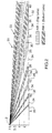
- Figure 2 shows how the upper lens 8 and the lower lens 14 cooperate for monitoring of the area 51.
- the passive infrared detector 2 is shown mounted on a wall or similar structure at an elevation of approximately 71 ⁇ 2 feet from the floor.
- the lens arrangement is looking forward and monitors the space 51.
- the distance grid along ground level is shown and it can be seen that two series of active zones 30 and 32 which alternate and are separated by a series of nonactive zones 34.
- the nonactive zones progressively narrow between active zones in a direction back towards the sensor.
- Zone 30 defines a response region where infrared radiation within the region is focused by the lens arrangement onto sensor 16.
- Infrared radiation within beams 32 is focused onto sensor 10.
- Infrared radiation in the nonactive zone is not focused on a sensor.
- the active zones tend to diverge, however, there is still considerable spacing of the beams between two and three feet above ground level.
- the spacing between the active zones above the two foot level narrows, rendering this region more responsive to infrared radiation sources. In this way, the detector provides vertical discrimination.
- the alternating zones 30 and 32 separated by the progressively narrowing nonactive zones produce vertical discrimination where the sensor within about twenty-five feet of the sensor is able to distinguish small domestic pets at ground level from larger and taller human intruders. Basically, the region within two feet of ground level and within twenty-five feet of the sensor is less responsive than a corresponding area above this two foot level. Small domestic pets have a large percentage of their volume normally in this lower region and false alarms from small domestic pets is reduced.
- the detector is not responsive to such a small infrared body, but would be responsive in a distance from six to approximately twenty feet if the upwardly narrowing nonactive zones were not present.
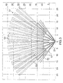
- Figure 3 also illustrates how a pattern of zones is used to cover the space 51 being monitored.
- a distant set of zones generally indicated as 53
- two intermediate sets of zones indicated as 55 and 57
- a close series of zones 59 The exact position of these zones is determined by the Fresnel lens shown in Figure 5.
- the lens 40 of Figure 5 has an upper section 42 and a lower section 44. Each of the sections 42 and 44 are divided horizontally and vertically to cover different areas of the region, and thus, define the alternating active zones separated by the narrowing nonactive zones.
- the passive infrared detector has been described with respect to the benefits in discriminating small, domestic pets from human intruders.
- Cats have previously posed considerable problems, as they can climb and even though they are relatively small, they can enter an area substantially above ground level, resulting in the detector receiving a relatively high level of infrared radiation and resulting in an alarm condition.
- the area immediately adjacent the detector should be kept free of chairs or other objects which would allow a cat to establish itself at a high point in front of the detector. If the cat is at a low level, such as ground level or below about 21 ⁇ 2 feet, it will cause considerable radiation to be received by one sensor, but the cat is not of sufficient size to cause a similar result in the other sensor.
- a human intruder due to the much greater size and height, will cause a high response in each sensor, causing an alarm to be produced.
- each signal is evaluated at different amplitude levels and processed as described in U.S. Patent 5,444,432.
- each signal is evaluated separately and an alarm signal is produced when both signals exceed a standard.
- the lens arrangement has rendered the area below two feet and within twenty-five feet of the detector less sensitive than a corresponding area above the two foot level.
- Other systems have tried to identify infrared radiation from pets and in contrast, the present invention reduces the possibility of receiving sufficient radiation from pets to cause an alarm.
- a simple approach for evaluating the signals from the two sensors is to merely add the two results and then compare this result with a predetermined threshold.
- a small domestic animal such as a cat, does not produce a response of sufficient magnitude in each sensor to cause it to exceed the alarm threshold.
- an intruder due to its size and normal vertical orientation, produces sufficient IR radiation to be immediately detected.
- This arrangement provides a simple approach for discriminating between different sizes of radiation sources. It has also been found that pets, such as dogs, of average size can also be discriminated in this way. It can be appreciated that the detector can also easily be adjusted for a particular application, if desired, by providing a variable threshold.
- thresholds can be set such that the animal does not cause an alarm while still being sensitive to a human intruder.
- a person can easily check this merely by setting the detector for the particular pet and then testing the system by entering the space himself and noting when a detection is made or using other test specimens, such as children.
- This arrangement provides a very efficient manner for size discrimination of moving IR radiation sources while still providing effective coverage of the space being monitored from unwanted intruders.
Landscapes
- Physics & Mathematics (AREA)
- General Physics & Mathematics (AREA)
- Burglar Alarm Systems (AREA)
- Photometry And Measurement Of Optical Pulse Characteristics (AREA)
- Details Of Television Scanning (AREA)
- Paper (AREA)
Claims (8)
- Ein Infrarot-Eindringlingsdetektor (2), der aus einem Gehäuse, das zwei PIR-Empfängermontagen (4, 6) enthält, besteht, wobei jede PIR-Empfängermontage eine Linsenmontage enthält (8, 14), die die IR-Strahlung aus vorbestimmten aktiven Zonen (53, 55, 57, 59) in einem zu überwachenden Raum in einem IR-Sensor (10, 16) bündelt, wodurch ein der empfangenen IR-Strahlung entsprechendes Signal erzeugt wird, wobei der o. g. Eindringlingsdetektor ein mit den o. g. Sensoren (10, 16) assoziiertes Signalverarbeitungsmittel (12) hat, das die Signale bearbeitet und auswertet und nach Bedarf ein der Signalauswertung entsprechendes Alarmsignal (24) erzeugt, wobei die o. g. Linsenmontagen (8, 14) zwei Sätze von alternierenden aktiven Zonen definieren, von denen ein Satz aktiver Zonen (30) mit einer PIR-Montage assoziiert ist, aber der zweite Satz alternierender Zonen (32) mit der anderen PIR-Montage assoziiert ist und benachbarte aktive Zonen durch eine nicht-ansprechende Zone (34) getrennt sind, wodurch die Ansprechung auf bodennahe Infrarotstrahlung von Strahlungsquellen in der Größe von kleinen Haustieren verringert wird.
- Ein Detektor (2), wie in Anspruch 1 beansprucht, wobei die Zonen senkrecht alternieren.
- Ein Detektor (2), wie in Anspruch 2 beansprucht, wobei die ersten und zweiten aktiven Zonensätze (30, 32) waagrecht alternieren und nicht-ansprechende Zonen in Bodennähe innerhalb von 12 m Abstand vom Detektor sich dazwischen befinden.
- Ein Detektor (2), wie in Anspruch 1 beansprucht, wobei innerhalb von 7,5 m Abstand von diesem Detektor (2) die o. g. aktiven Zonensätze (30, 32) von nicht-ansprechenden Zonen (34) getrennt sind und nach ungefähr 7,5 m und einer Höhe von 1,25 m diese aktiven Zonensätze (30, 32) sich gegenseitig überschneiden.
- Ein Detektor (2), wie in Anspruch 2 beansprucht, wobei die o. g. aktiven Zonensätze (30, 32) auch in waagrechter Richtung alternieren.
- Ein Detektor (2), wie in Anspruch 1 beansprucht, wobei die o. g. nicht-ansprechenden Zonen (34) zwischen dem Boden und 60 cm Höhe innerhalb von 7,5 m vom Detektor (2) im Verhältnis zu den entsprechenden nicht-ansprechenden Zonen (14) über dem 60 cm Niveau größer sind.
- Ein Infrarot-Eindringlingsdetektor (2), wie in Anspruch 1 beansprucht, wobei die o. g. aktiven Zonen (53, 55, 57, 59) durch nicht-ansprechende Zonen (34) voneinander senkrecht getrennt sind und diese senkrechten aktiven Zonen sowie die.nicht-ansprechende Zonen (34) so angeordnet sind, daß eine Hauskatze, die sich irgendwo zwischen 1,8 m und 7,5 m vom Detektor (2) entfernt befindet, nicht ausreichende Einwirkung auf die naheliegenden aktiven Zonen (53, 55, 57, 59) hat und daß ihre IR-Strahlung, wie sie von den beiden PIR-Empfängermontagen (4, 5) aufgenommen wird, dem Mindestwert nicht genügt, der die Anwesenheit eines Eindringlings anzeigt.
- Ein passiver IR-Detektor (2), wie in Anspruch 7 beansprucht, wobei aktive und nicht-ansprechende Zonen so groß sind, daß eine bodennahe Katze innerhalb von 7,5 m vom Detektor zwei nebeneinander liegende aktive Zonen unzureichend unterbricht und daß die o. g. PIR-Empfängermontagen (4, 6) von der Katze nur IR-Strahlung empfangen, die nicht ausreicht, um ein Alarmsignal zu erzeugen (24).
Applications Claiming Priority (3)
| Application Number | Priority Date | Filing Date | Title |
|---|---|---|---|
| CA002196014A CA2196014C (en) | 1997-01-27 | 1997-01-27 | Size discriminating dual element pir detector |
| CA2196014 | 1997-01-27 | ||
| PCT/CA1998/000051 WO1998033154A1 (en) | 1997-01-27 | 1998-01-27 | Size discriminating dual element pir detector |
Publications (2)
| Publication Number | Publication Date |
|---|---|
| EP0954835A1 EP0954835A1 (de) | 1999-11-10 |
| EP0954835B1 true EP0954835B1 (de) | 2001-10-24 |
Family
ID=4159757
Family Applications (1)
| Application Number | Title | Priority Date | Filing Date |
|---|---|---|---|
| EP98901288A Expired - Lifetime EP0954835B1 (de) | 1997-01-27 | 1998-01-27 | Grössenunterscheidender doppelelement-pir-detektor |
Country Status (3)
| Country | Link |
|---|---|
| EP (1) | EP0954835B1 (de) |
| AU (1) | AU729608B2 (de) |
| DE (1) | DE69802164T2 (de) |
Families Citing this family (2)
| Publication number | Priority date | Publication date | Assignee | Title |
|---|---|---|---|---|
| DE102011106037A1 (de) * | 2011-06-30 | 2013-01-03 | Xtralis Ag | Verfahren zum Betreiben von Anlagen mit PIR-Detektoren |
| DE102011115468A1 (de) * | 2011-10-10 | 2013-04-11 | Xtralis Ag | Meldeanlage mit Positionsbestimmung |
Family Cites Families (3)
| Publication number | Priority date | Publication date | Assignee | Title |
|---|---|---|---|---|
| DE3666887D1 (en) * | 1985-09-02 | 1989-12-14 | Heimann Gmbh | Infrared movement detector |
| JPS62121523U (de) * | 1986-01-24 | 1987-08-01 | ||
| EP0624857B1 (de) * | 1993-05-11 | 1998-09-09 | Optex Co. Ltd. | Detektierungssystem des passiven Typs von sich bewegendem Objekt |
-
1998
- 1998-01-27 EP EP98901288A patent/EP0954835B1/de not_active Expired - Lifetime
- 1998-01-27 AU AU57448/98A patent/AU729608B2/en not_active Expired
- 1998-01-27 DE DE69802164T patent/DE69802164T2/de not_active Expired - Lifetime
Also Published As
| Publication number | Publication date |
|---|---|
| EP0954835A1 (de) | 1999-11-10 |
| DE69802164T2 (de) | 2002-06-13 |
| DE69802164D1 (de) | 2001-11-29 |
| AU5744898A (en) | 1998-08-18 |
| AU729608B2 (en) | 2001-02-08 |
Similar Documents
| Publication | Publication Date | Title |
|---|---|---|
| US5923250A (en) | Size discriminating dual element PIR detector | |
| US7034675B2 (en) | Intrusion detection system including over-under passive infrared optics and a microwave transceiver | |
| CA2220813C (en) | Passive infrared motion detector and method | |
| US6462663B1 (en) | Use of detector arrays to detect cessation of motion | |
| US20100019903A1 (en) | Passive infrared detector | |
| US5101194A (en) | Pattern-recognizing passive infrared radiation detection system | |
| US20120105229A1 (en) | System and method for intruder detection | |
| US9797769B2 (en) | Infrared detection device and masking section | |
| EP0624857A1 (de) | Detektierungssystem des passiven Typs von sich bewegendem Objekt | |
| US6265972B1 (en) | Pet resistant pir detector | |
| US7619517B2 (en) | Alarm for selectively detecting intrusions by persons | |
| CA2300644C (en) | Pet resistant pir detector | |
| AU729608B2 (en) | Size discriminating dual element pir detector | |
| AU2001242129A1 (en) | Pet resistant PIR detector | |
| US20080029703A1 (en) | System and method for range selectable motion detection | |
| JP4203998B2 (ja) | 受動型赤外線センサ | |
| WO2000013153A1 (en) | Infrared intruder recognition method and apparatus | |
| JP3458738B2 (ja) | 人体検知装置 | |
| JP4120475B2 (ja) | 防犯装置 | |
| RU2292597C1 (ru) | Охранный извещатель с инфракрасным каналом обнаружения | |
| CN115497251B (zh) | 人体晕倒躺卧姿态检测告警方法及其检测装置 | |
| JPH0581576A (ja) | 人体検知器 | |
| RU49318U1 (ru) | Охранный извещатель с инфракрасным каналом обнаружения | |
| JP4222482B2 (ja) | 受動型赤外線センサ | |
| JP3025220U (ja) | 赤外線式防犯警報装置 |
Legal Events
| Date | Code | Title | Description |
|---|---|---|---|
| PUAI | Public reference made under article 153(3) epc to a published international application that has entered the european phase |
Free format text: ORIGINAL CODE: 0009012 |
|
| 17P | Request for examination filed |
Effective date: 19990709 |
|
| AK | Designated contracting states |
Kind code of ref document: A1 Designated state(s): DE FR GB IT |
|
| GRAG | Despatch of communication of intention to grant |
Free format text: ORIGINAL CODE: EPIDOS AGRA |
|
| 17Q | First examination report despatched |
Effective date: 20001120 |
|
| GRAG | Despatch of communication of intention to grant |
Free format text: ORIGINAL CODE: EPIDOS AGRA |
|
| GRAG | Despatch of communication of intention to grant |
Free format text: ORIGINAL CODE: EPIDOS AGRA |
|
| GRAH | Despatch of communication of intention to grant a patent |
Free format text: ORIGINAL CODE: EPIDOS IGRA |
|
| GRAH | Despatch of communication of intention to grant a patent |
Free format text: ORIGINAL CODE: EPIDOS IGRA |
|
| ITF | It: translation for a ep patent filed | ||
| GRAA | (expected) grant |
Free format text: ORIGINAL CODE: 0009210 |
|
| AK | Designated contracting states |
Kind code of ref document: B1 Designated state(s): DE FR GB IT |
|
| REF | Corresponds to: |
Ref document number: 69802164 Country of ref document: DE Date of ref document: 20011129 |
|
| REG | Reference to a national code |
Ref country code: GB Ref legal event code: IF02 |
|
| ET | Fr: translation filed | ||
| PLBE | No opposition filed within time limit |
Free format text: ORIGINAL CODE: 0009261 |
|
| STAA | Information on the status of an ep patent application or granted ep patent |
Free format text: STATUS: NO OPPOSITION FILED WITHIN TIME LIMIT |
|
| 26N | No opposition filed | ||
| REG | Reference to a national code |
Ref country code: FR Ref legal event code: CD |
|
| REG | Reference to a national code |
Ref country code: FR Ref legal event code: PLFP Year of fee payment: 19 |
|
| REG | Reference to a national code |
Ref country code: FR Ref legal event code: PLFP Year of fee payment: 20 |
|
| PGFP | Annual fee paid to national office [announced via postgrant information from national office to epo] |
Ref country code: FR Payment date: 20170125 Year of fee payment: 20 Ref country code: DE Payment date: 20170125 Year of fee payment: 20 |
|
| PGFP | Annual fee paid to national office [announced via postgrant information from national office to epo] |
Ref country code: GB Payment date: 20170127 Year of fee payment: 20 |
|
| PGFP | Annual fee paid to national office [announced via postgrant information from national office to epo] |
Ref country code: IT Payment date: 20170124 Year of fee payment: 20 |
|
| REG | Reference to a national code |
Ref country code: DE Ref legal event code: R071 Ref document number: 69802164 Country of ref document: DE |
|
| REG | Reference to a national code |
Ref country code: GB Ref legal event code: PE20 Expiry date: 20180126 |
|
| PG25 | Lapsed in a contracting state [announced via postgrant information from national office to epo] |
Ref country code: GB Free format text: LAPSE BECAUSE OF EXPIRATION OF PROTECTION Effective date: 20180126 |