EP0954989A2 - Anlage zur Futtermittelherstellung - Google Patents
Anlage zur Futtermittelherstellung Download PDFInfo
- Publication number
- EP0954989A2 EP0954989A2 EP99108981A EP99108981A EP0954989A2 EP 0954989 A2 EP0954989 A2 EP 0954989A2 EP 99108981 A EP99108981 A EP 99108981A EP 99108981 A EP99108981 A EP 99108981A EP 0954989 A2 EP0954989 A2 EP 0954989A2
- Authority
- EP
- European Patent Office
- Prior art keywords
- expander
- container
- cooler
- pellet press
- processor
- Prior art date
- Legal status (The legal status is an assumption and is not a legal conclusion. Google has not performed a legal analysis and makes no representation as to the accuracy of the status listed.)
- Granted
Links
- 239000000463 material Substances 0.000 claims abstract description 31
- 239000008188 pellet Substances 0.000 claims abstract description 18
- 238000009434 installation Methods 0.000 claims abstract description 3
- 238000004519 manufacturing process Methods 0.000 claims description 2
- 238000011144 upstream manufacturing Methods 0.000 claims description 2
- 238000000034 method Methods 0.000 abstract description 3
- XLYOFNOQVPJJNP-UHFFFAOYSA-N water Substances O XLYOFNOQVPJJNP-UHFFFAOYSA-N 0.000 description 17
- 239000007789 gas Substances 0.000 description 8
- 238000001816 cooling Methods 0.000 description 5
- 238000010438 heat treatment Methods 0.000 description 5
- 235000019645 odor Nutrition 0.000 description 4
- 239000002918 waste heat Substances 0.000 description 3
- 238000009833 condensation Methods 0.000 description 2
- 230000005494 condensation Effects 0.000 description 2
- 230000003750 conditioning effect Effects 0.000 description 2
- 238000009413 insulation Methods 0.000 description 2
- 239000007788 liquid Substances 0.000 description 2
- 235000013379 molasses Nutrition 0.000 description 2
- 230000035943 smell Effects 0.000 description 2
- 239000007858 starting material Substances 0.000 description 2
- 239000000126 substance Substances 0.000 description 2
- 239000000654 additive Substances 0.000 description 1
- 230000001143 conditioned effect Effects 0.000 description 1
- 239000000428 dust Substances 0.000 description 1
- 230000000694 effects Effects 0.000 description 1
- 238000003912 environmental pollution Methods 0.000 description 1
- 238000001704 evaporation Methods 0.000 description 1
- 230000008020 evaporation Effects 0.000 description 1
- 239000002803 fossil fuel Substances 0.000 description 1
- 239000008187 granular material Substances 0.000 description 1
- 230000007257 malfunction Effects 0.000 description 1
- 239000000203 mixture Substances 0.000 description 1
- 238000011084 recovery Methods 0.000 description 1
Images

Classifications
-
- A—HUMAN NECESSITIES
- A23—FOODS OR FOODSTUFFS; TREATMENT THEREOF, NOT COVERED BY OTHER CLASSES
- A23N—MACHINES OR APPARATUS FOR TREATING HARVESTED FRUIT, VEGETABLES OR FLOWER BULBS IN BULK, NOT OTHERWISE PROVIDED FOR; PEELING VEGETABLES OR FRUIT IN BULK; APPARATUS FOR PREPARING ANIMAL FEEDING- STUFFS
- A23N17/00—Apparatus specially adapted for preparing animal feeding-stuffs
- A23N17/005—Apparatus specially adapted for preparing animal feeding-stuffs for shaping by moulding, extrusion, pressing, e.g. pellet-mills
Definitions
- the invention relates to a plant for the production of feed with a metering device, with a continuous mixer, with an expander in which the material is brought to high pressure and high temperature by mechanical processing and then expanded, with a pellet press and with a cooler connected to it.
- the throughput through the system is determined with a metering device.
- a continuous mixer that follows, the material is thoroughly mixed again, in which case liquid or gaseous additives (water, molasses, fat, steam, etc.) can also be added.
- the material then passes into an expander, where it is pressed by a conveying element against a counterpressure element that at least partially closes the outlet.
- the temperature increases as a result of the mechanical processing.
- the material also reaches a temperature above 100 ° C. without the water contained therein evaporates.
- the material is then relaxed and processed into pellets in a pellet press (DE-B-0 331 207).
- the animal feed which is strongly heated in the expander and also in the pellet press, is then cooled in a downstream cooler.
- the material from which the feed is to be produced usually has a very unpleasant smell at the considerable temperatures which occur, so that there is the further problem that large amounts of exhaust air have to be cleaned.
- the object of the invention is to create a system of the type mentioned which is ecologically significantly more advantageous and in which energy and water can be saved and the odor nuisance can be reduced.
- the solution according to the invention consists in that a processor container is connected upstream of the expander, in which material is poured in from above and drawn off at the bottom, a gas escaping through holes in the bottom of the container, which material Flows through from bottom to top, and that vapors are used as gas, which are taken from the expander, the pellet press and / or the cooler.
- An additional processor container is therefore provided, which is known per se by filling in material from above and pulling it off again at the bottom.
- Appropriate fill level indicators advantageously keep the level of the material in the processor container approximately constant.
- a gas is blown from below through openings. This gas consists of the vapors (contaminated steam quantities), which are extracted from the expander, the pellet press and / or the cooler.
- the vapors are heavily moisture-laden, less water needs to be added to the material. Rather, this absorbs the water from the vapors that flow through the processor tank from bottom to top. A large part of the odorous substances that are released at the higher temperatures is also bound by the cool starting material that is located in the processor container. By countercurrent cooling or countercurrent heating, the material is heated more and more as it moves downward, so that less energy then has to be supplied for heating. Overall, there is an energy saving through waste heat recovery and a water saving because the vapors are used to moisten the starting material.
- the cooler is connected to the gas inlet by a suction fan via a pipeline Processor container connected. This allows waste heat and water vapor from the cooling feed to be recovered. The odorous substances that are still released in the cooler are also largely absorbed by the new material entering the system.
- the outlet end of the expander is connected to the gas inlet of the processor tank by a suction fan via a pipe, particularly large amounts of steam are returned.
- expanding i. H. the sudden lowering of the working pressure to atmospheric pressure, namely the water contained in the material evaporates suddenly, so that large amounts of steam are released at a temperature of approximately 100 ° C. It is particularly advantageous if these are then passed through the suction fan into the processor container.
- the outlet end of the expander can also be connected to the gas inlet of the processor container by a suction fan via a pipe. Not only is the hot steam generated at the exit end of the expander, but also the steam that is released at the exit end of the pellet press is reused and reused.
- the emission of odors is reduced by approximately 80%.
- the processor container also has a good mechanical filter effect, which means a 50% reduction in dust emissions. Finally, considerable amounts of water are saved.
- the exhaust gas temperature is also significantly lower.
- the material is better conditioned (pretreatment), which also means that the expander runs more smoothly and therefore less wear. Due to the fact that better conditioning is carried out, the system is also less prone to malfunction, since the machines are less stressed. Since the mechanical energy that is introduced into the expander and the pellet press to operate them is converted into heat, it is also recovered.
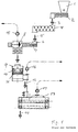
- the conventional system in FIG. 1 has a storage container 1 for the finished mixture and a metering device 2.
- the material is then passed into a continuous mixer 4, in which liquids, steam, molasses, fat, etc. can be added. It then arrives in the direction of arrow 5 in the expander 6 where it is pressed against a counter-pressure element 8 by a screw-shaped conveying element 7 and thereby brought to increased working pressure, the temperature also increasing due to the mechanical processing.
- steam can be added.
- the pellets or granules thus produced are passed in the direction of arrow 12 into a cooler 13 and then transported away in the direction of arrow 14.
- the expander 6 is provided with a suction fan 15 in order to discharge exhaust air.
- a suction fan 16 is correspondingly provided at the outlet of the pellet press 9, and a suction fan 17 is provided on the cooler.
- the exhaust air with its thermal energy and water content is therefore diverted unused. The environment is significantly disturbed by smells, unless complex filters are provided.
- the metering cell 2 and the continuous mixer 4 can be made considerably smaller and are assembled in the embodiment shown. This is based on the additional conditioning (heating and humidification) in the processor container 18, into which the material is filled from above and, in the embodiment shown, is passed below into the expander 6 via a conveyor screw 19.
- the outlet of the expander is provided with a suction fan 20, which also sucks in the exhaust air from the outlet of the pellet press 9 and presses it into the material from below through holes in the bottom of the processor container 18.
- the exhaust air then passes through the material in the container 18 and exits at the top, but has largely emitted heat, water vapor and odors to the material.
- Exhaust air from the cooler 13 is finally passed through a blower 21 into the processor container 18, so that the cooling air of the last cooler stage, which escapes in the direction of arrow 23, has a much smaller volume than in previously known systems.
- a lower one The exhaust air in this area has a temperature, a lower water content and a lower odor pollution due to the lower temperature of the material in this area of the cooler, so that the environmental pollution is correspondingly low.
- insulation and heating of a pipeline is also indicated schematically. All the pipelines mentioned are expediently insulated and heated for the vapors.
Landscapes
- Life Sciences & Earth Sciences (AREA)
- Chemical & Material Sciences (AREA)
- Engineering & Computer Science (AREA)
- Food Science & Technology (AREA)
- Polymers & Plastics (AREA)
- Apparatuses For Bulk Treatment Of Fruits And Vegetables And Apparatuses For Preparing Feeds (AREA)
- Steroid Compounds (AREA)
- Fodder In General (AREA)
- Fertilizers (AREA)
Abstract
Description
- Die Erfindung betrifft eine Anlage zur Futtermittelherstellung mit einer Dosiereinrichtung, mit einem Durchlaufmischer, mit einem Expander, in dem das Material durch mechanische Bearbeitung auf hohen Druck und hohe Temperatur gebracht und anschließend entspannt wird, mit einer Pelletpresse und mit einem sich daran anschließenden Kühler.
- Bei einer solchen Anlage wird mit einer Dosiereinrichtung der Durchsatz durch die Anlage bestimmt. In einem sich daran anschließenden Durchlaufmischer wird das Material noch einmal gründlich gemischt, wobei dann auch flüssige oder gasförmige Zusätze (Wasser, Melasse, Fett, Dampf usw.) zugegeben werden können. Anschließend gelangt das Material in einen Expander, wo es durch ein Förderelement gegen ein den Ausgang wenigstens teilweise verschließendes Gegendruckelement gedrückt wird. Dabei erhöht sich die Temperatur durch die mechanische Bearbeitung. In Folge des mechanischen Arbeitsdrucks, der ausgeübt wird, erzielt das Material dabei auch eine über 100° C liegende Temperatur, ohne daß das darin enthaltene Wasser verdampft. Anschließend wird das Material dann entspannt und in einer Pelletpresse zu Pellets verarbeitet (DE-B-0 331 207). Das im Expander und auch in der Pelletpresse durch die mechanische Bearbeitung stark erwärmte Futtermittel wird dann in einem nachgeschalteten Kühler abgekühlt.
- Bei dem Verfahren tritt beträchtliche Wärme auf, und zwar aufgrund der Beaufschlagung mit Dampf und der mechanischen Bearbeitung im Expander und in der Pelletpresse. Das ursprünglich beigegebene Wasser oder Wasserdampf verdampft insbesondere am Ausgang des Expanders, wenn das Material schlagartig auf Atmosphärendruck entspannt wird. Auch im Bereich der Pelletpresse tritt aber eine beträchtliche Verdampfung auf. Der Wasserdampf geht dabei normalerweise verloren.
- Das Material, aus dem die Futtermittel hergestellt werden sollen, hat meistens bei den beträchtlichen auftretenden Temperaturen einen sehr unangenehmen Geruch, so daß das weitere Problem besteht, daß große Mengen von Abluft gereinigt werden müssen.
- Die Aufgabe der Erfindung besteht demgegenüber darin, eine Anlage der Eingangs genannten Art zu schaffen, das ökologisch wesentlich vorteilhafter ist und bei der Energie und Wasser eingespart werden und die Geruchsbelästigung vermindert werden kann.
- Die erfindungsgemäße Lösung besteht darin, daß dem Expander ein Prozessorbehälter vorgeschaltet ist, in dem von oben Material eingefüllt und unten abgezogen wird, wobei am Boden des Behälters durch Bohrungen ein Gas austritt, das das Material von unten nach oben durchströmt, und daß als Gas Brüden verwendet werden, die dem Expander, der Pelletpresse und/oder dem Kühler entnommen werden.
- Es wird also ein zusätzlicher Prozessorbehälter vorgesehen, der an sich bekannt ist, indem von oben Material eingefüllt und unten wieder abgezogen wird. Durch entsprechende Füllstandsmelder wird dabei vorteilhafterweise der Pegel des Materials im Prozessorbehälter ungefähr konstant gehalten. Von unten wird durch Öffnungen ein Gas eingeblasen. Dieses Gas besteht aus den Brüden (verunreinigten Dampfmengen), die aus dem Expander, der Pelletpresse und/oder dem Kühler entnommen werden.
- Dadurch, daß die Brüden stark feuchtigkeitsbeladen sind, braucht dem Material weniger Wasser zugeführt werden. Dieses nimmt das Wasser vielmehr aus den Brüden auf, die den Prozessorbehälter von unten nach oben durchströmen. Dabei wird auch ein großer Teil der Geruchsstoffe, der bei den höheren Temperaturen freigesetzt ist, durch das kühle Ausgangsmaterial, das sich im Prozessorbehälter befindet, gebunden. Durch die Gegenstromkühlung bzw. Gegenstromerwärmung wird das Material, wenn es sich nach unten bewegt, immer mehr erwärmt, so daß anschließend weniger Energie zum Erwärmen zugeführt werden muß. Insgesamt resultiert also eine Energieeinsparung durch Abwärmerückgewinnung und eine Wassereinsparung dadurch, daß die Brüden zur Befeuchtung des Ausgangsmaterials verwendet werden.
- Bei einer vorteilhaften Ausführungsform ist der Kühler durch ein Sauggebläse über eine Rohrleitung mit dem Gaseintritt des Prozessorbehälters verbunden. Dadurch kann Abwärme und Wasserdampf des abkühlenden Futtermittels zurückgewonnen werden. Auch die Geruchsstoffe, die im Kühler noch freigesetzt werden, werden zum großen Teil durch das neu in die Anlage eintretende Material absorbiert.
- Wenn das Ausgangsende des Expanders durch ein Sauggebläse über eine Rohrleitung mit dem Gaseintritt des Prozessorbehälters verbunden ist, werden besonders große Dampfmengen zurückgeführt. Beim Expandieren, d. h. dem schlagartigen Senken des Arbeitsdrucks auf Atmosphärendruck, verdampft nämlich schlagartig das im Material enthaltende Wasser, so daß hier große Dampfmengen bei einer Temperatur von ungefähr 100°C freigesetzt werden. Es ist besonders vorteilhaft, wenn diese dann durch das Sauggebläse in den Prozessorbehälter geleitet werden.
- Dabei kann auch das Ausgangsende des Expanders durch ein Sauggebläse über eine Rohrleitung mit dem Gaseintritt des Prozessorbehälters verbunden sein. Es wird dann nicht nur der heiße Dampf, der am Ausgangsende des Expanders entsteht, sondern auch der Dampf abgeleitet und wieder verwendet, der am Ausgangsende der Pelletpresse freigesetzt wird.
- Durch die Rohrleitungen wird im wesentlichen Wasserdampf geleitet. Damit dieser nicht an den Wänden der Rohrleitungen kondensiert, wird zweckmäßigerweise vorgesehen, daß die Rohrleitungen isoliert und beheizt sind. Bei entsprechender Isolierung kann aber die Heizleistung sehr knapp bemessen werden. Insgesamt zeigt sich, daß durch die erfindungsgemäße Anlage gegenüber herkömmlichen Anlagen entscheidende Einsparungen erzielt werden können. Ungefähr 50 % der Abwärme kann zurückgewonnen werden. Da im Grunde alle Energie, die in die Anlage eingegeben wird, in Wärme umgewandelt wird, bedeutet dies auch 50 % Energieersparnis und damit eine 50%ige Reduktion des CO2-Ausstoßes von Kraftwerken mit fossilen Brennstoffen, die zur Energieerzeugung notwendig sind.
- Die Emission von Gerüchen wird um ungefähr 80 % reduziert. Der Prozessorbehälter hat aber auch eine gute mechanische Filterwirkung, was 50 % Reduktion von Staubemission bedeutet. Schließlich werden erhebliche Wassermengen eingespart. Auch die Abgastemperatur ist wesentlich geringer.
- Durch die Erfindung werden also folgende Vorteile erzielt. Da eine Erwärmung bereits im Prozessorbehälter erfolgt, sind kleinere Durchlaufmischer oder gar keine Durchlaufmischer mehr erforderlich. Dies bedeutet eine weitere Energieeinsparung. Es tritt keine Kondensation von Wasser im Kühler auf, da die Brüden dauernd abgesaugt werden. Im Rohrleitungssystem kann keine Kondensation auftreten, wenn die Rohre gut isoliert und ggf. beheizt sind. Die Rohrleitungsquerschnitte, mit denen Kühlluft direkt vom Kühler nach außen geleitet werden, sind geringer und es wird weniger Kühlluft benötigt, da das Futtermittel zunächst im heißeren Bereich des Kühlers mit Luft gekühlt wird, die dann abgesaugt und in den Prozessorbehälter wieder eingeführt wird. Wegen der geringeren Dampfmenge, die benötigt wird, kann ein kleinerer Dampfkessel benutzt werden. Andererseits ist es bei bestehenden Anlagen, die erweitert werden sollen, nicht notwendig, den Dampfkessel durch einen größeren zu ersetzen. Wegen der Verweilzeit des Materials im Prozessorbehälter erhält man eine bessere Konditionierung (Vorbehandlung) des Materials, was auch einen ruhigeren Lauf des Expanders und damit weniger Verschleiß bedeutet. Aufgrund der Tatsache, daß besser konditioniert wird, ist die Anlage auch weniger störungsanfällig, da die Maschinen weniger beansprucht werden. Da die mechanische Energie, die in den Expander und die Pelletpresse zum Betrieb derselben eingebracht werden in Wärme umgewandelt wird, wird sie ebenfalls zurückgewonnen.
- Die Erfindung wird im folgenden anhand einer vorteilhaften Ausführungsform unter Bezugnahme auf die beigefügten Zeichnungen beispielsweise beschrieben. Es zeigen:
- Fig. 1
- in einer schematischen Darstellung eine konventionelle Anlage; und
- Fig. 2
- eine Anlage der Erfindung.
- Die konventionelle Anlage der Fig. 1 weist einen Vorratsbehälter 1 für die fertige Mischung und eine Dosiereinrichtung 2 auf. In Richtung des Pfeiles 3 wird dann das Material in einen Durchlaufmischer 4 geleitet, in dem Flüssigkeiten, Dampf, Melasse, Fett usw. zugegeben werden können. Es gelangt dann in Richtung des Pfeiles 5 in den Expander 6 wo es durch ein schneckenförmiges Förderelement 7 gegen ein Gegendruckelement 8 gedrückt und dadurch auf erhöhten Arbeitsdruck gebracht wird, wobei sich durch die mechanische Bearbeitung auch die Temperatur erhöht. Auch hier kann wiederum Dampf zuzugeben werden. Wenn das Material den Expander 6 verläßt, wird es entspannt und in eine Pelletpresse 9 geleitet, wo es durch Kollerrollen 10 durch eine Matrize 11 hindurchgedrückt wird. Die so erzeugten Pellets bzw. das Granulat wird in Richtung des Pfeiles 12 in einen Kühler 13 geleitet und anschließend in Richtung des Pfeiles 14 abtransportiert. Der Expander 6 ist dabei mit einem Sauggebläse 15 versehen, um Abluft abzuführen. Am Ausgang der Pelletpresse 9 ist entsprechend ein Sauggebläse 16, am Kühler ein Sauggebläse 17 vorgesehen. Die Abluft mit ihrer Wärmeenergie und Wassergehalt wird also ungenutzt abgeleitet. Die Umwelt wird erheblich durch Gerüche belästigt, falls nicht aufwendige Filter vorgesehen sind.
- Beim erfindungsgemäßen Verfahren können Dosierzelle 2 und Durchlaufmischer 4 erheblich kleiner gestaltet werden und sind bei der gezeigten Ausführungsform zusammengebaut. Dies beruht auf der zusätzlichen Konditionierung (Erwärmung und Befeuchtung) im Prozessorbehälter 18, in den das Material von oben eingefüllt und unten in der gezeigten Ausführungsform über eine Förderschnecke 19 in den Expander 6 geleitet wird. Der Ausgang des Expanders ist mit einem Sauggebläse 20 versehen, das auch die Abluft vom Ausgang der Pelletpresse 9 ansaugt und über Löcher im Boden des Prozessorbehälters 18 von unten in das Material hineindrückt. Die Abluft durchstreicht dann das Material im Behälter 18 und tritt oben aus, hat dabei aber Wärme, Wasserdampf und Gerüche zum großen Teil an das Material abgegeben. Durch ein Gebläse 21 wird schließlich noch Abluft vom Kühler 13 in den Prozessorbehälter 18 geleitet, so daß die Kühlluft der letzten Kühlerstufe, die in Richtung des Pfeiles 23 entweicht, ein wesentlich kleineres Volumen hat als bei vorbekannten Anlagen. Eine niedrigere Temperatur, einen niedrigeren Wassergehalt und eine niedrigere Geruchsbelastung hat die Abluft in diesem Bereich aufgrund der niedrigeren Temperatur des Materials in diesem Bereich des Kühlers, so daß die Umweltbelastung entsprechend gering ist.
- Bei 22 ist noch eine Isolierung und Beheizung einer Rohrleitung schematisch angedeutet. Zweckmäßigerweise sind alle erwähnten Rohrleitungen für die Brüden isoliert und beheizt.
Claims (6)
- Anlage zur Futtermittelherstellung mit einer Dosiereinrichtung, mit einem Durchlaufmischer, mit einem Expander, in dem das Material durch mechanische Bearbeitung auf hohen Druck und hohe Temperatur gebracht und anschließend entspannt wird, mit einer Pelletpresse und mit einem sich daran anschließenden Küler, dadurch gekennzeichnet, daß dem Expander (6) ein Prozessorbehälter (18) vorgeschaltet ist, in den von oben Material eingefüllt und unten abgezogen wird, wobei aus dem Boden des Behälters (18) durch Bohrungen ein Gas austritt, das das Material von unten nach oben durchströmt, und daß als Gas Brüden verwendet werden, die dem Expander (6), der Pelletpresse (9) und/oder dem Kühler (13) entnommen werden.
- Anlage nach Anspruch 1, dadurch gekennzeichnet, daß das Material bis zu einer konstant gehaltenen Höhe in den Prozessorbehälter (18) eingefüllt wird.
- Anlage nach Anspruch 1 oder 2, dadurch gekennzeichnet, daß der Kühler (13) durch ein Sauggebläse (21) über eine Rohrleitung mit dem Gaseintritt des Prozessorbehälters (18) verbunden ist.
- Anlage nach einem der Ansprüche 1 bis 3, dadurch gekennzeichnet, daß das Ausgangsende des Expanders (6) durch ein Sauggebläse (20) über eine Rohrleitung mit dem Gaseintritt des Prozessorbehälters (18) verbunden ist.
- Anlage nach Anspruch 4, dadurch gekennzeichnet, daß das Ausgangsende des Expanders (6) über eine Rohrleitung mit dem Ausgangsende der Pelletpresse (9) verbunden ist.
- Anlage nach einem der Ansprüche 3 bis 5, dadurch gekennzeichnet, daß die Rohrleitungen isoliert und beheizt sind.
Applications Claiming Priority (2)
| Application Number | Priority Date | Filing Date | Title |
|---|---|---|---|
| DE29808392U DE29808392U1 (de) | 1998-05-08 | 1998-05-08 | Anlage zur Futtermittelherstellung |
| DE29808392U | 1998-05-08 |
Publications (3)
| Publication Number | Publication Date |
|---|---|
| EP0954989A2 true EP0954989A2 (de) | 1999-11-10 |
| EP0954989A3 EP0954989A3 (de) | 2000-04-12 |
| EP0954989B1 EP0954989B1 (de) | 2002-11-27 |
Family
ID=8056929
Family Applications (1)
| Application Number | Title | Priority Date | Filing Date |
|---|---|---|---|
| EP99108981A Expired - Lifetime EP0954989B1 (de) | 1998-05-08 | 1999-05-06 | Anlage zur Futtermittelherstellung |
Country Status (5)
| Country | Link |
|---|---|
| EP (1) | EP0954989B1 (de) |
| AT (1) | ATE228314T1 (de) |
| DE (2) | DE29808392U1 (de) |
| DK (1) | DK0954989T3 (de) |
| ES (1) | ES2188056T3 (de) |
Cited By (2)
| Publication number | Priority date | Publication date | Assignee | Title |
|---|---|---|---|---|
| EP1932644A1 (de) * | 2006-12-13 | 2008-06-18 | Amandus Kahl GmbH & Co. KG | Verfahren und Vorrichtung zum Herstellen von Granulaten |
| CN1730166B (zh) * | 2005-05-17 | 2010-07-21 | 章春根 | 动态配料液体后喷洒系统 |
Families Citing this family (3)
| Publication number | Priority date | Publication date | Assignee | Title |
|---|---|---|---|---|
| DE19903313A1 (de) * | 1999-01-28 | 2000-08-10 | Edwin Eisenegger | Verfahren zum Herstellen von Mischfutter in verdichteter Form und Vorrichtung zum Durchführen desselben |
| DE50013172D1 (de) * | 1999-02-11 | 2006-08-31 | Deuka Deutsche Tiernahrung Gmb | Verfahren und Vorrichtung zur Herstellung von Zwischenprodukten und Mischfutterprodukten für Tiere |
| DE102006002199B4 (de) * | 2006-01-16 | 2011-03-10 | Bühler AG | Verfahren und Vorrichtung zur kontinuierlichen, hygienisierenden Behandlung von Futtermitteln |
Citations (1)
| Publication number | Priority date | Publication date | Assignee | Title |
|---|---|---|---|---|
| EP0331207B1 (de) | 1988-04-27 | 1991-12-04 | Amandus Kahl Nachf. (GmbH & Co.) | Verfahren zum Pelletieren |
Family Cites Families (2)
| Publication number | Priority date | Publication date | Assignee | Title |
|---|---|---|---|---|
| US4721448A (en) * | 1985-12-19 | 1988-01-26 | Adolph Coors Company | Pelletizer with moisture control system |
| EP0522220A1 (de) * | 1991-07-09 | 1993-01-13 | Consergra, S.A. | Vorrichtung zum Kühlen von Viehfutter und ähnlichem Material |
-
1998
- 1998-05-08 DE DE29808392U patent/DE29808392U1/de not_active Expired - Lifetime
-
1999
- 1999-05-06 DE DE59903508T patent/DE59903508D1/de not_active Expired - Lifetime
- 1999-05-06 EP EP99108981A patent/EP0954989B1/de not_active Expired - Lifetime
- 1999-05-06 ES ES99108981T patent/ES2188056T3/es not_active Expired - Lifetime
- 1999-05-06 AT AT99108981T patent/ATE228314T1/de not_active IP Right Cessation
- 1999-05-06 DK DK99108981T patent/DK0954989T3/da active
Patent Citations (1)
| Publication number | Priority date | Publication date | Assignee | Title |
|---|---|---|---|---|
| EP0331207B1 (de) | 1988-04-27 | 1991-12-04 | Amandus Kahl Nachf. (GmbH & Co.) | Verfahren zum Pelletieren |
Cited By (2)
| Publication number | Priority date | Publication date | Assignee | Title |
|---|---|---|---|---|
| CN1730166B (zh) * | 2005-05-17 | 2010-07-21 | 章春根 | 动态配料液体后喷洒系统 |
| EP1932644A1 (de) * | 2006-12-13 | 2008-06-18 | Amandus Kahl GmbH & Co. KG | Verfahren und Vorrichtung zum Herstellen von Granulaten |
Also Published As
| Publication number | Publication date |
|---|---|
| ES2188056T3 (es) | 2003-06-16 |
| EP0954989B1 (de) | 2002-11-27 |
| ATE228314T1 (de) | 2002-12-15 |
| DE59903508D1 (de) | 2003-01-09 |
| DK0954989T3 (da) | 2003-03-24 |
| EP0954989A3 (de) | 2000-04-12 |
| DE29808392U1 (de) | 1998-07-16 |
Similar Documents
| Publication | Publication Date | Title |
|---|---|---|
| EP3111148B1 (de) | Verfahren zur trocknung von schüttgut | |
| EP0243778A2 (de) | Verfahren und Vorrichtung zum Reinigen von Abgasen | |
| EP0383227B1 (de) | Verfahren zum Binden von partikelförmigen Abfällen, wie Stäube, Metallabfälle, Fasern, Papierabfällen od. dgl., zu Feststoffen | |
| DE10142906A1 (de) | Verfahren zum Aufbereiten von Restmüll und Restmüllaufbereitungsanlage | |
| EP0543133B1 (de) | Verfahren und Vorrichtung zur Behandlung eines zu einem Dickschlamm entwässerten Klärschlammes | |
| EP0043567A1 (de) | Verfahren und Rostfeuerung zur Verfeuerung fester Brennstoffe | |
| EP0954989B1 (de) | Anlage zur Futtermittelherstellung | |
| EP1319632A1 (de) | Verfahren und Vorrichtung zur Trocknung von Schlamm, insbesondere von Abwasserschlamm | |
| EP2062963A2 (de) | Verfahren und Vorrichtung zur energiesparenden und umweltschonenden Verarbeitung von Ölsaaten | |
| DE2442122A1 (de) | Pyrolyse-behaelter | |
| CH645333A5 (en) | Moist composting process for organic waste materials, for example sewage sludge, and apparatus for carrying out the process | |
| EP0571722B1 (de) | Verfahren und anlagentechnische Schaltung zur Trocknung und Verbrennung von Abfallstoffen | |
| DE19903313A1 (de) | Verfahren zum Herstellen von Mischfutter in verdichteter Form und Vorrichtung zum Durchführen desselben | |
| EP0413992A2 (de) | Verfahren und Vorrichtung zur aeroben, fermentativen Hydrolyse, insbesondere zur Kompostierung von organischen Stoffen | |
| DE19825597A1 (de) | Verfahren sowie Anlage zum Trocknen von Feuchtgut | |
| DE2535683A1 (de) | Verfahren und vorrichtung zur verbrennung von schlaemmen mit hilfe rekuperativer schlammtrocknung | |
| DE102018007810A1 (de) | Verwertung von ausgefaultem Klärschlamm in einer Wirbelschichtfeuerung | |
| WO2008083703A1 (de) | Verfahren zum trocknen von festen und/oder flüssigen abfallstoffen | |
| EP1527808A1 (de) | Vorrichtung und Verfahren zur Konditionierung eines Gasgemisches | |
| DE3644807A1 (de) | Verfahren zur behandlung der abluft einer durchlaufreinigungsanlage und anlage zur durchfuehrung des verfahrens | |
| DE3535721A1 (de) | Vorrichtung zur herstellung von alkaliarmem zementklinker | |
| EP0375913A2 (de) | Verfahren zur Rückfürung von Flugasche mit Bestimmtem Feuchtigkeitsanteil in eine Verbrennungsanlage zur Zerstörung von in der Flugasche Enthalten Organischen Schadestoffen | |
| DE69014776T2 (de) | Vorrichtung zur Reduktion von Stickoxyden aus Verbrennungsgasen. | |
| EP0422509B1 (de) | Verfahren zur Entgasung von Anlagen | |
| DE1584906C (de) | Verfahren und Einrichtung zur Entwas serung von festen Schlammkonzentraten |
Legal Events
| Date | Code | Title | Description |
|---|---|---|---|
| PUAI | Public reference made under article 153(3) epc to a published international application that has entered the european phase |
Free format text: ORIGINAL CODE: 0009012 |
|
| AK | Designated contracting states |
Kind code of ref document: A2 Designated state(s): AT BE CH DE DK ES FI FR GB GR IE IT LI NL PT SE |
|
| AX | Request for extension of the european patent |
Free format text: AL;LT;LV;MK;RO;SI |
|
| PUAL | Search report despatched |
Free format text: ORIGINAL CODE: 0009013 |
|
| AK | Designated contracting states |
Kind code of ref document: A3 Designated state(s): AT BE CH CY DE DK ES FI FR GB GR IE IT LI LU MC NL PT SE |
|
| AX | Request for extension of the european patent |
Free format text: AL;LT;LV;MK;RO;SI |
|
| 17P | Request for examination filed |
Effective date: 20001011 |
|
| AKX | Designation fees paid |
Free format text: AT BE CH DE DK ES FI FR GB GR IE IT LI NL PT SE |
|
| GRAG | Despatch of communication of intention to grant |
Free format text: ORIGINAL CODE: EPIDOS AGRA |
|
| 17Q | First examination report despatched |
Effective date: 20020305 |
|
| GRAG | Despatch of communication of intention to grant |
Free format text: ORIGINAL CODE: EPIDOS AGRA |
|
| GRAH | Despatch of communication of intention to grant a patent |
Free format text: ORIGINAL CODE: EPIDOS IGRA |
|
| GRAH | Despatch of communication of intention to grant a patent |
Free format text: ORIGINAL CODE: EPIDOS IGRA |
|
| GRAA | (expected) grant |
Free format text: ORIGINAL CODE: 0009210 |
|
| AK | Designated contracting states |
Kind code of ref document: B1 Designated state(s): AT BE CH DE DK ES FI FR GB GR IE IT LI NL PT SE |
|
| PG25 | Lapsed in a contracting state [announced via postgrant information from national office to epo] |
Ref country code: IE Free format text: LAPSE BECAUSE OF FAILURE TO SUBMIT A TRANSLATION OF THE DESCRIPTION OR TO PAY THE FEE WITHIN THE PRESCRIBED TIME-LIMIT Effective date: 20021127 Ref country code: GR Free format text: LAPSE BECAUSE OF FAILURE TO SUBMIT A TRANSLATION OF THE DESCRIPTION OR TO PAY THE FEE WITHIN THE PRESCRIBED TIME-LIMIT Effective date: 20021127 |
|
| REF | Corresponds to: |
Ref document number: 228314 Country of ref document: AT Date of ref document: 20021215 Kind code of ref document: T |
|
| REG | Reference to a national code |
Ref country code: GB Ref legal event code: FG4D Free format text: NOT ENGLISH |
|
| REG | Reference to a national code |
Ref country code: CH Ref legal event code: EP |
|
| REG | Reference to a national code |
Ref country code: IE Ref legal event code: FG4D Free format text: GERMAN |
|
| REF | Corresponds to: |
Ref document number: 59903508 Country of ref document: DE Date of ref document: 20030109 |
|
| REG | Reference to a national code |
Ref country code: CH Ref legal event code: NV Representative=s name: TROESCH SCHEIDEGGER WERNER AG |
|
| PG25 | Lapsed in a contracting state [announced via postgrant information from national office to epo] |
Ref country code: SE Free format text: LAPSE BECAUSE OF FAILURE TO SUBMIT A TRANSLATION OF THE DESCRIPTION OR TO PAY THE FEE WITHIN THE PRESCRIBED TIME-LIMIT Effective date: 20030227 Ref country code: PT Free format text: LAPSE BECAUSE OF FAILURE TO SUBMIT A TRANSLATION OF THE DESCRIPTION OR TO PAY THE FEE WITHIN THE PRESCRIBED TIME-LIMIT Effective date: 20030227 |
|
| REG | Reference to a national code |
Ref country code: DK Ref legal event code: T3 |
|
| GBT | Gb: translation of ep patent filed (gb section 77(6)(a)/1977) |
Effective date: 20030315 |
|
| PG25 | Lapsed in a contracting state [announced via postgrant information from national office to epo] |
Ref country code: AT Free format text: LAPSE BECAUSE OF NON-PAYMENT OF DUE FEES Effective date: 20030506 |
|
| PG25 | Lapsed in a contracting state [announced via postgrant information from national office to epo] |
Ref country code: BE Free format text: LAPSE BECAUSE OF NON-PAYMENT OF DUE FEES Effective date: 20030531 |
|
| REG | Reference to a national code |
Ref country code: ES Ref legal event code: FG2A Ref document number: 2188056 Country of ref document: ES Kind code of ref document: T3 |
|
| ET | Fr: translation filed | ||
| REG | Reference to a national code |
Ref country code: IE Ref legal event code: FD4D Ref document number: 0954989E Country of ref document: IE |
|
| PLBQ | Unpublished change to opponent data |
Free format text: ORIGINAL CODE: EPIDOS OPPO |
|
| PLBI | Opposition filed |
Free format text: ORIGINAL CODE: 0009260 |
|
| PLAX | Notice of opposition and request to file observation + time limit sent |
Free format text: ORIGINAL CODE: EPIDOSNOBS2 |
|
| 26 | Opposition filed |
Opponent name: EDWIN EISENEGGER Effective date: 20030808 |
|
| BERE | Be: lapsed |
Owner name: AMANDUS *KAHL G.M.B.H. & CO. Effective date: 20030531 |
|
| NLR1 | Nl: opposition has been filed with the epo |
Opponent name: EDWIN EISENEGGER |
|
| PLAX | Notice of opposition and request to file observation + time limit sent |
Free format text: ORIGINAL CODE: EPIDOSNOBS2 |
|
| PLBB | Reply of patent proprietor to notice(s) of opposition received |
Free format text: ORIGINAL CODE: EPIDOSNOBS3 |
|
| PLCK | Communication despatched that opposition was rejected |
Free format text: ORIGINAL CODE: EPIDOSNREJ1 |
|
| PGFP | Annual fee paid to national office [announced via postgrant information from national office to epo] |
Ref country code: GB Payment date: 20050425 Year of fee payment: 7 |
|
| PGFP | Annual fee paid to national office [announced via postgrant information from national office to epo] |
Ref country code: NL Payment date: 20050518 Year of fee payment: 7 |
|
| PGFP | Annual fee paid to national office [announced via postgrant information from national office to epo] |
Ref country code: FR Payment date: 20050519 Year of fee payment: 7 |
|
| PGFP | Annual fee paid to national office [announced via postgrant information from national office to epo] |
Ref country code: FI Payment date: 20050523 Year of fee payment: 7 |
|
| PGFP | Annual fee paid to national office [announced via postgrant information from national office to epo] |
Ref country code: CH Payment date: 20050524 Year of fee payment: 7 |
|
| PGFP | Annual fee paid to national office [announced via postgrant information from national office to epo] |
Ref country code: DK Payment date: 20050525 Year of fee payment: 7 |
|
| PGFP | Annual fee paid to national office [announced via postgrant information from national office to epo] |
Ref country code: ES Payment date: 20050531 Year of fee payment: 7 |
|
| PLBN | Opposition rejected |
Free format text: ORIGINAL CODE: 0009273 |
|
| STAA | Information on the status of an ep patent application or granted ep patent |
Free format text: STATUS: OPPOSITION REJECTED |
|
| 27O | Opposition rejected |
Effective date: 20050325 |
|
| NLR2 | Nl: decision of opposition |
Effective date: 20050325 |
|
| PG25 | Lapsed in a contracting state [announced via postgrant information from national office to epo] |
Ref country code: GB Free format text: LAPSE BECAUSE OF NON-PAYMENT OF DUE FEES Effective date: 20060506 Ref country code: FI Free format text: LAPSE BECAUSE OF NON-PAYMENT OF DUE FEES Effective date: 20060506 |
|
| PG25 | Lapsed in a contracting state [announced via postgrant information from national office to epo] |
Ref country code: ES Free format text: LAPSE BECAUSE OF NON-PAYMENT OF DUE FEES Effective date: 20060508 |
|
| PG25 | Lapsed in a contracting state [announced via postgrant information from national office to epo] |
Ref country code: LI Free format text: LAPSE BECAUSE OF NON-PAYMENT OF DUE FEES Effective date: 20060531 Ref country code: DK Free format text: LAPSE BECAUSE OF NON-PAYMENT OF DUE FEES Effective date: 20060531 Ref country code: CH Free format text: LAPSE BECAUSE OF NON-PAYMENT OF DUE FEES Effective date: 20060531 |
|
| PG25 | Lapsed in a contracting state [announced via postgrant information from national office to epo] |
Ref country code: NL Free format text: LAPSE BECAUSE OF NON-PAYMENT OF DUE FEES Effective date: 20061201 |
|
| REG | Reference to a national code |
Ref country code: CH Ref legal event code: PL Ref country code: DK Ref legal event code: EBP |
|
| GBPC | Gb: european patent ceased through non-payment of renewal fee |
Effective date: 20060506 |
|
| NLV4 | Nl: lapsed or anulled due to non-payment of the annual fee |
Effective date: 20061201 |
|
| REG | Reference to a national code |
Ref country code: FR Ref legal event code: ST Effective date: 20070131 |
|
| REG | Reference to a national code |
Ref country code: ES Ref legal event code: FD2A Effective date: 20060508 |
|
| PG25 | Lapsed in a contracting state [announced via postgrant information from national office to epo] |
Ref country code: FR Free format text: LAPSE BECAUSE OF NON-PAYMENT OF DUE FEES Effective date: 20060531 |
|
| PGFP | Annual fee paid to national office [announced via postgrant information from national office to epo] |
Ref country code: IT Payment date: 20150519 Year of fee payment: 17 |
|
| PG25 | Lapsed in a contracting state [announced via postgrant information from national office to epo] |
Ref country code: IT Free format text: LAPSE BECAUSE OF NON-PAYMENT OF DUE FEES Effective date: 20160506 |
|
| PGFP | Annual fee paid to national office [announced via postgrant information from national office to epo] |
Ref country code: DE Payment date: 20170721 Year of fee payment: 19 |
|
| REG | Reference to a national code |
Ref country code: DE Ref legal event code: R119 Ref document number: 59903508 Country of ref document: DE |
|
| PG25 | Lapsed in a contracting state [announced via postgrant information from national office to epo] |
Ref country code: DE Free format text: LAPSE BECAUSE OF NON-PAYMENT OF DUE FEES Effective date: 20181201 |