EP0955100A1 - Beschichtungsgerät vom typ mit einem druckknopf - Google Patents
Beschichtungsgerät vom typ mit einem druckknopf Download PDFInfo
- Publication number
- EP0955100A1 EP0955100A1 EP98955914A EP98955914A EP0955100A1 EP 0955100 A1 EP0955100 A1 EP 0955100A1 EP 98955914 A EP98955914 A EP 98955914A EP 98955914 A EP98955914 A EP 98955914A EP 0955100 A1 EP0955100 A1 EP 0955100A1
- Authority
- EP
- European Patent Office
- Prior art keywords
- writing tip
- valve element
- diameter
- sleeve
- coating liquid
- Prior art date
- Legal status (The legal status is an assumption and is not a legal conclusion. Google has not performed a legal analysis and makes no representation as to the accuracy of the status listed.)
- Withdrawn
Links
Images


Classifications
-
- B—PERFORMING OPERATIONS; TRANSPORTING
- B43—WRITING OR DRAWING IMPLEMENTS; BUREAU ACCESSORIES
- B43K—IMPLEMENTS FOR WRITING OR DRAWING
- B43K8/00—Pens with writing-points other than nibs or balls
- B43K8/02—Pens with writing-points other than nibs or balls with writing-points comprising fibres, felt, or similar porous or capillary material
- B43K8/022—Pens with writing-points other than nibs or balls with writing-points comprising fibres, felt, or similar porous or capillary material with writing-points comprising fibres
-
- B—PERFORMING OPERATIONS; TRANSPORTING
- B05—SPRAYING OR ATOMISING IN GENERAL; APPLYING FLUENT MATERIALS TO SURFACES, IN GENERAL
- B05C—APPARATUS FOR APPLYING FLUENT MATERIALS TO SURFACES, IN GENERAL
- B05C17/00—Hand tools or apparatus using hand held tools, for applying liquids or other fluent materials to, for spreading applied liquids or other fluent materials on, or for partially removing applied liquids or other fluent materials from, surfaces
- B05C17/005—Hand tools or apparatus using hand held tools, for applying liquids or other fluent materials to, for spreading applied liquids or other fluent materials on, or for partially removing applied liquids or other fluent materials from, surfaces for discharging material from a reservoir or container located in or on the hand tool through an outlet orifice by pressure without using surface contacting members like pads or brushes
- B05C17/00503—Details of the outlet element
- B05C17/00506—Means for connecting the outlet element to, or for disconnecting it from, the hand tool or its container
- B05C17/00509—Means for connecting the outlet element to, or for disconnecting it from, the hand tool or its container of the bayonet type
-
- A—HUMAN NECESSITIES
- A45—HAND OR TRAVELLING ARTICLES
- A45D—HAIRDRESSING OR SHAVING EQUIPMENT; EQUIPMENT FOR COSMETICS OR COSMETIC TREATMENTS, e.g. FOR MANICURING OR PEDICURING
- A45D34/00—Containers or accessories specially adapted for handling liquid toiletry or cosmetic substances, e.g. perfumes
- A45D34/04—Appliances specially adapted for applying liquid, e.g. using roller or ball
-
- A—HUMAN NECESSITIES
- A46—BRUSHWARE
- A46B—BRUSHES
- A46B11/00—Brushes with reservoir or other means for applying substances, e.g. paints, pastes, water
- A46B11/001—Brushes with reservoir or other means for applying substances, e.g. paints, pastes, water with integral reservoirs
-
- B—PERFORMING OPERATIONS; TRANSPORTING
- B43—WRITING OR DRAWING IMPLEMENTS; BUREAU ACCESSORIES
- B43K—IMPLEMENTS FOR WRITING OR DRAWING
- B43K24/00—Mechanisms for selecting, projecting, retracting or locking writing units
- B43K24/02—Mechanisms for selecting, projecting, retracting or locking writing units for locking a single writing unit in only fully projected or retracted positions
- B43K24/08—Mechanisms for selecting, projecting, retracting or locking writing units for locking a single writing unit in only fully projected or retracted positions operated by push-buttons
-
- B—PERFORMING OPERATIONS; TRANSPORTING
- B43—WRITING OR DRAWING IMPLEMENTS; BUREAU ACCESSORIES
- B43M—BUREAU ACCESSORIES NOT OTHERWISE PROVIDED FOR
- B43M11/00—Hand or desk devices of the office or personal type for applying liquid, other than ink, by contact to surfaces, e.g. for applying adhesive
- B43M11/06—Hand-held devices
- B43M11/08—Hand-held devices of the fountain-pen type
Definitions
- This invention relates to a knock type applicator or a coating device which contains a suitable coating liquid such as, a writing and painting liquid such as India ink, paint and ink, a cosmetic liquid such as eye liner and lip color, a writing correction liquid, and adhesives, and serves to move a prescribed member by knocking it so that a valve mechanism disposed in the applicator is opened to discharge the liquid.
- a suitable coating liquid such as, a writing and painting liquid such as India ink, paint and ink, a cosmetic liquid such as eye liner and lip color, a writing correction liquid, and adhesives
- an applicator (a coating device) which comprises a cylindrical shell with a coating liquid storage chamber defined therein, a coating body such as a pen point and a writing tip secured to an opening portion formed in a distal end of the cylindrical shell, and a valve mechanism disposed between the coating body and the coating liquid storage chamber.
- a knock portion disposed on the cylindrical shell is knocked or pushed to move a movable member disposed in the coating liquid storage chamber and the movable member, in turn, moves a valve element to open the valve mechanism so that the coating liquid is ready to be discharged from the storage chamber to an object to be coated.
- the conventional device has such problems that when the device is not used for a long period of time or when the cover member is left removed, the coating liquid stored in the coating body and between the coating body and an inner wall of the opening portion of the distal end of the cylindrical shell is prone to create hardened substance, gelled substance and viscous substance due to evaporation of moisture and solvent thereby choking the flow passage for the coating liquid, and therefore, a smooth flow of the coating liquid is interrupted.
- Japanese Utility Model Publication No. 2-309 of 1989 discloses a writing device with a side knock valve having a writing body with a valve element fixed thereto and capable of containing therein a liquid, and the writing body is slidably inserted in a cavity formed in a distal end of a cylindrical shell, and a pigment ink flow passage formed between an outer surface of the writing body and an inner surface of the distal end of the cylindrical shell, and at least a part of the resilient cylindrical shell is defined as a resilient body, the resilient body being displaced by knocking the cylindrical shell so that the valve element and writing body will be slidingly moved simultaneously.
- the coating body is slidingly moved simultaneously with the opening operation of the valve element which is made by knocking the cylindrical shell, for the purpose of flowing ink smoothly by recovering the ink flow passage, just in case the flow passage is choked with ink composition which has been hardened by drying, in such a manner as to peel off and/or crush the lumps of ink.
- the writing device of the above utility model publication can recover a region of the coating liquid flow passage between the coating body and the inner wall of the distal end portion of the cylindrical shell, it is impossible for this device to recover a region of the coating liquid flow passage in the coating body which passage is choked with the hardened substance, gelled substance and viscous substance of the coating liquid.
- an object of the present invention to provide a knock type applicator or a coating device in which when it occurs that a coating liquid can not be discharged smoothly due to adhesion of fibers of a writing tip caused by hardened substance, gelled substance and viscous substance created by the coating liquid in the writing tip, the hardened substance, etc. are peeled off or crushed by a sliding movement of the writing tip so that the coating liquid can be discharged again in a smooth manner.
- the present invention employs a construction in which ribs are formed in an inner wall of an opening portion formed in a distal end of a cylindrical shell in a lengthwise direction of the cylindrical shell, and the diameter of an inscribed circle connecting apexes of the ribs is dimensioned smaller than the maximum diameter of the writing tip.
- the ribs formed on the inner wall of an opening portion of a distal end of the cylindrical shell bite or project into the writing tip which advances in operative connection with a valve element during knocking operation.
- the writing tip is cracked by the ribs projected therein.
- the hardened substance, gelled substance and viscous substance which are created from the coating liquid in the writing tip are peeled off successfully from the fibers of the writing tip.
- an ink flow passage in the writing tip can be recovered.
- an end face of the opening portion formed in the distal end of the cylindrical shell serves as a fulcrum for the writing tip to make a flexible bowing movement, the ribs bite or project deep into the writing tip to crack it so that the hardened substance, gelled substance and the viscous substance in the writing tip are peeled off and/or crushed from the fibers of the writing tip and discharged outside the writing tip together with the coating liquid. Therefore, the writing tip is hardly adhered after the coating liquid is discharged.
- the adhered writing tip is loosened by rubbing it to the surface of a sheet of paper or loosened by fingers or other similar means, in order to remove the hardened substance, gelled substance and viscous substance.
- the above-mentioned means is carried out while slidingly moving the writing tip.
- the present invention has such other additive structural features as described hereinafter, in addition to the above-mentioned construction as a basic feature.
- the other additive structural features are: a force for connecting the writing tip and valve element together is smaller than a biasing force exerted to the valve element, and a joining distance between the writing tip and the valve element is longer than a moving distance of the valve element during knocking operation of a knock portion.
- the writing tip is projected from the cylindrical shell as far as possible by knocking operation and then the writing tip is picked up with fingers. If the knocking force exerted to the knock portion is released accidentally or by mistake during a removing operation, the valve element is moved backward and the writing tip is moved relatively forward. At that time, if the connecting force between the writing tip and the valve element is smaller than the biasing force exerted to the valve element, there is such a fear that the writing tip is escaped from the valve element, thus making it unable to carry out coating operation.
- the above problems can be solved amicably and even if the knocking force is released by mistake, the writing tip does not escape from the valve element.
- Figs. 1 to 4 show Embodiment 1 of the present invention.
- reference numeral 1 denotes a rear shell having a coating liquid storage chamber 2 defined therein and reference numeral 3 denotes a front shell whose front portion (upward portion in Fig. 1) is in the formed of a reduced-diameter portion and whose rear portion is in the form of an enlarged-diameter portion.
- the front shell 3 is fixedly inserted into an opening portion formed in a distal end of the rear shell until a flange portion 3b formed on an outer wall of the enlarged-diameter portion of the front shell 3 is brought into abutment with a front end face of the rear shell 1, thereby forming a cylindrical shell.
- the front shell 3 has a stepped portion 3a formed on an inner wall of the reduced-diameter portion. Since this stepped portion 3a is provided as an abutment portion with respect to a coating body as later described, it may take any desired configuration inasmuch as it can abut with the coating body. For example, ribs may be formed on the front shell 3 or a hole may be formed in the reduced-diameter portion so that the hole is reduced in diameter forwardly.
- a writing tip 4 is slidably disposed in an opening portion formed in a distal end of this cylindrical shell.
- the writing tip 4 is composed of a plurality of natural fibers such as those of weasels (or martens), horses and pigs, synthetic resin fibers such as nylon, polyethylene terephthalate and acrylic fibers, or a mixture there of converged in a lengthwise direction.
- the writing tip 4 includes, at one part thereof, a straight portion 4b whose rear end face is fixed, heat welding or bonding to form a flange portion 4a and at the other part, a tapered portion 4c which is reduced in outer diameter towards a front end face thereof.
- a writing tip fixing tube 5 is a sleeve-like member having a through hole which comprises an enlarged-diameter hole portion 5a and a reduced-diameter hole portion 5b.
- This sleeve-like member has a larger outside diameter than an inside diameter of the opening portion formed in the distal end of the cylindrical shell and also serves as connecting portion between the writing tip 4 and a valve element as later described.
- the writing tip 4 is fixedly held between the stepped portion 5c and a front end face of a valve element which will be described presently, with a front portion there of projecting from the opening portion in the distal end and with the flange portion 4a formed on a rear end portion thereof being in abutment with a stepped portion 5c which is formed on a boundary between the enlarged-diameter hole portion 5a and the reduced-diameter hole portion 5b which hole portions are both formed in the writing tip fixing tube 5.
- a plurality of ribs 3c are formed on the inner wall of the opening portion of the front shell 3 so that the ribs 3c are formed in the distal end in a lengthwise direction (see Fig. 3).
- the height of the ribs is dimensioned such that the diameter of the inscribed circle connecting the apexes of the ribs 3c is smaller than the maximum outside diameter of the writing tip 4.
- increased height of the ribs 4c is associated with such inconveniences that size of the crack in the writing tip 4 is increased with the result of difficulties in discharging the coating liquid and, as a matter of fact, the number of ribs 4c is limited. Therefore, the height and number of the ribs can appropriately be set within a range satisfying the above conditions, in accordance with physical properties of the coating liquid and what use of the coating device.
- the ribs 3b and the tapered portion 4c are in confronting relation during non-knocking operation and the ribs 3b and the straight portion 4b are in confronting relation during knocking operation. Accordingly, the ribs 3b and the writing tip 4 are away from each other during non-knocking operation, while the former 3b bites or project into the latter 4 during a knocking operation.
- This valve mechanism is comprised of a cover member 6 formed with a bottom portion 6a and a valve element 7 formed with a valve portion 7a.
- the valve element 7 is brought into abutment with the seat portion 6a by a spring member, which will be described presently.
- the cover member 6 is comprised of a front reduced-diameter sleeve-like portion 6b and a rear enlarged-diameter sleeve-like portion 6c.
- a circumferential projection 6d directing inward is formed on an inner wall of the reduced-diameter sleeve-like portion 6c and the seat portion 6a is formed on a front end face of this circumferential projection 6d.
- the cover member 6 is fixedly press-fitted to the inner wall of the rear shell 1 by the enlarged-diameter sleeve-like portion 6c and serves to cover the coating liquid storage chamber 2 defined in the rear shell 1.
- the valve element 7 is comprised of a front sleeve-like portion 7b and a rear sleeve-like portion 7c.
- a valve portion 7a is formed between the front sleeve-like portion 7b and the rear sleeve-like portion 7c.
- the front sleeve-like portion 7b and valve portion 7a of the valve element 7 are slidably disposed in the reduced-diameter sleeve-like portion 6b of the cover member 6.
- the valve element 7 is biased backward (namely, towards the knock member 10) by a resilient member 8 such as a coiled spring.
- valve element 7 and the writing tip 4 are connected together with the front sleeve-like portion 7b of the valve element 7 fixedly inserted in the writing tip fixing tube 5.
- the joining distance between the valve element 7 and the writing tip 4 is equal to the insertion length of the front sleeve-like portion 7b into the writing tip fixing tube. It is preferred that the joining distance is set longer than the moving distance of the valve element 7 during knocking operation, for the purpose of prevention of dropping or escape of the writing tip.
- the connecting force between the writing tip 4 and the valve element 7, i.e., between the front sleeve-like portion 7b of the valve element 7 and the writing tip fixing tube 5 is preferably smaller than the biasing force of the spring member 8 with respect to the valve element 7. By doing so, breakage of the writing tip 4 (especially, flange portion 4a) can be prevented.
- the connecting force can appropriately be set by adjusting the outside diameter of the front sleeve-like portion 7b and the inside diameter of the writing tip fixing tube 5.
- the rear rod-like portion 7c of the valve element 7 is fixedly inserted in a front portion of a sleeve-like member 9 which is disposed in the coating liquid storage chamber 2 defined in the rear shell 1.
- the sleeve-like member 9 has a rear portion inserted in a sleeve-like knock member 10 having a bottom which is formed on a rear end of the coating liquid storage chamber 2.
- the knock member 10 has a bellows-like movable portion 10a. It is fixedly inserted to the outer side of the reduced-diameter sleeve-like portion 1a formed on the rear end of the rear shell 1.
- knock portion can employ the method known per se and is, by no means, limited to the constructions shown in the embodiment of the invention.
- the bellows-like movable member 10a is contracted to move the sleeve-like member 9 forward.
- the valve element 7 moves forward against the spring force of the spring member 8, to thereby open the valve mechanism. Since the writing tip 4 is connected to the valve element 7 at that time, they move forward together. Since the ribs 3c of the front shell 3 bite or project into the writing tip 4 due to the forward movement of the writing tip 4, the writing tip is cracked forwardly at the area where the ribs project into.
- the coating liquid in the coating liquid storage chamber moves into the front shell 3 and discharged outside through gaps among the fibers of the writing tip 4 and a gap between the writing tip and the inner wall of the opening portion formed in the distal end of the front shell 3.
- the coating liquid discharged outside the front shell 3 is absorbed by and stored in the distal end portion of the writing tip 4 so that it is ready to be coated.
- the space for the coating liquid to pass through is not sufficiently large due to presence of the hardened substance, gelled substance and viscous substance of the coating liquid in the writing tip 4, the hardened substance, etc. present at that portion of the writing tip into which the ribs project are peeled off and/or crushed. As a consequence, the coating liquid is absorbed by and stored in that portion so as to be ready for coating.
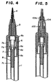
- Figs. 5 and 6 show Embodiment 2 according to the present invention.
- Embodiment 2 is same as Embodiment 1 except that the writing tip 4 is replaced by a writing tip 104 with no tapered portion.
- ribs 103c of a front shell 103 bite or project into the writing tip 104 even during non-knocking operation unlike previous Embodiment 1, the front end portion of the writing tip is cracked. As a consequence, the coating liquid discharged in the front shell during knocking operation is supplied to the front end of the writing tip through the crack even after the knocking operation is canceled. This makes it possible to discharge the coating liquid over a wide range of area in a stable manner.
- ribs may take various configurations and shapes as desired.
- Embodiment 3 is same as Embodiment 1 except that a front shell 203 is provided with ribs 203c each having an acute apex.
- Embodiment 3 when compared with Embodiment 1, since the apex of each rib first contacted by the writing tip during knocking operation is acute, resistance encountered by the ribs when they bite into the writing tip is small and therefore, the writing tip is not unnecessarily deformed. Accordingly, those employing the ribs each having an acute apex exhibit such features that the writing tip is readily restored to the state before the knocking operation is made, during non-knocking operation.
- Fig. 8 shows Embodiment 4, which is same as Embodiment 1 except that a front shell 303 is provided with ribs 303c having a straight portion 303d and a tapered portion 303e.
- Embodiment 4 when compared with Embodiment 1, since the ribs, when the writing tip contacts the advanced ribs at the time of the knocking operation, bite into the writing tip from the tapered portion, resistance encountered by the ribs when they bite into the writing tip is small and therefore, the writing tip is not unnecessarily deformed. Accordingly, it exhibits such features that the writing tip is readily restored to the state before the knocking operation is made, during non-knocking operation.
Landscapes
- Engineering & Computer Science (AREA)
- Mechanical Engineering (AREA)
- Pens And Brushes (AREA)
- Coating Apparatus (AREA)
Applications Claiming Priority (3)
| Application Number | Priority Date | Filing Date | Title |
|---|---|---|---|
| JP34442597 | 1997-11-28 | ||
| JP34442597A JP3312316B2 (ja) | 1997-11-28 | 1997-11-28 | ノック式塗布具 |
| PCT/JP1998/005293 WO1999028046A1 (en) | 1997-11-28 | 1998-11-25 | Push-button type coating instrument |
Publications (2)
| Publication Number | Publication Date |
|---|---|
| EP0955100A1 true EP0955100A1 (de) | 1999-11-10 |
| EP0955100A4 EP0955100A4 (de) | 2005-06-22 |
Family
ID=18369167
Family Applications (1)
| Application Number | Title | Priority Date | Filing Date |
|---|---|---|---|
| EP98955914A Withdrawn EP0955100A4 (de) | 1997-11-28 | 1998-11-25 | Beschichtungsgerät vom typ mit einem druckknopf |
Country Status (7)
| Country | Link |
|---|---|
| US (1) | US6210063B1 (de) |
| EP (1) | EP0955100A4 (de) |
| JP (1) | JP3312316B2 (de) |
| KR (1) | KR100498081B1 (de) |
| CN (1) | CN1099324C (de) |
| TW (1) | TW515382U (de) |
| WO (1) | WO1999028046A1 (de) |
Families Citing this family (15)
| Publication number | Priority date | Publication date | Assignee | Title |
|---|---|---|---|---|
| EP1446457A1 (de) * | 2001-11-19 | 2004-08-18 | Sanford L.P. | Metallicfarbe und fasermarker |
| CA2478627A1 (en) * | 2002-04-01 | 2003-10-16 | Sanford, L.P. | Solvent system and ink made therefrom |
| US7467907B2 (en) | 2003-08-19 | 2008-12-23 | Sanford, L.P. | Valve mechanisms for paint or ink brush with integrated reservoir |
| US7481593B2 (en) | 2003-08-19 | 2009-01-27 | Sanford, L.P. | Combination hydrophobic/hydrophilic filters/reservoirs for controlling fluid flow |
| CN100421596C (zh) * | 2003-12-02 | 2008-10-01 | 株式会社常盘 | 带涂敷工具的容器 |
| US20050202386A1 (en) * | 2004-03-15 | 2005-09-15 | Jehan Clements | Flip-over storytelling book publishing system, method, and kit |
| JP2006068297A (ja) * | 2004-09-02 | 2006-03-16 | Tokiwa Corp | 塗布具 |
| KR101107647B1 (ko) * | 2009-05-08 | 2012-01-20 | 김명자 | 용액도포기 |
| US9163153B2 (en) | 2013-03-15 | 2015-10-20 | Sanford, L.P. | Metallic ink composition and writing instrument containing same |
| USD717995S1 (en) | 2013-11-08 | 2014-11-18 | International Cosmetic Suppliers Ltd. | Eyeliner applicator |
| JP6406970B2 (ja) | 2014-10-16 | 2018-10-17 | 株式会社呉竹 | ペン及びペン用リフィル |
| KR102135043B1 (ko) * | 2018-05-24 | 2020-07-17 | 조지원 | 관로가 형성된 탄성부재를 구비하는 아이라이너 |
| KR102135046B1 (ko) * | 2018-05-24 | 2020-07-17 | 조지원 | 돌출리브가 형성된 노즐을 구비하는 아이라이너 |
| CN113195110A (zh) * | 2018-12-06 | 2021-07-30 | Teibow有限公司 | 中继芯、笔尖单元及液体涂布工具 |
| CN113080599A (zh) * | 2020-01-09 | 2021-07-09 | 上海创元化妆品有限公司 | 化妆笔 |
Family Cites Families (11)
| Publication number | Priority date | Publication date | Assignee | Title |
|---|---|---|---|---|
| JPS58147783U (ja) | 1982-03-31 | 1983-10-04 | ぺんてる株式会社 | サイドノツク弁付筆記具 |
| US4792252A (en) * | 1985-02-27 | 1988-12-20 | Pittway Corporation | Liquid applicator device |
| DE3681317D1 (de) * | 1985-02-27 | 1991-10-17 | Flocon Inc | Geraet zum auftragen von fluessigkeit. |
| US4913175A (en) * | 1985-07-19 | 1990-04-03 | Pilot Ink Co., Ltd. | Liquid-applying tip assembly |
| JPH0621745Y2 (ja) * | 1987-05-08 | 1994-06-08 | 三菱鉛筆株式会社 | 液状体の筆記又は塗布用器具に於けるバルブ装置 |
| JPS6469679A (en) * | 1987-09-09 | 1989-03-15 | Canon Kk | Image recording ink |
| JPH0169679U (de) * | 1987-10-28 | 1989-05-09 | ||
| EP0625378B1 (de) * | 1993-04-27 | 1999-08-25 | Sakura Color Products Corporation | Flüssigkeitsauftragegerät und Herstellung desselben |
| KR100320764B1 (ko) * | 1993-11-30 | 2002-06-20 | 아사베 히로시 | 도포기 |
| JP3679849B2 (ja) * | 1995-12-25 | 2005-08-03 | 三菱鉛筆株式会社 | 液体塗布具 |
| JP3570075B2 (ja) * | 1996-03-29 | 2004-09-29 | ぺんてる株式会社 | 塗布具 |
-
1997
- 1997-11-28 JP JP34442597A patent/JP3312316B2/ja not_active Expired - Fee Related
-
1998
- 1998-11-25 TW TW091203103U patent/TW515382U/zh unknown
- 1998-11-25 WO PCT/JP1998/005293 patent/WO1999028046A1/ja not_active Ceased
- 1998-11-25 CN CN98802129A patent/CN1099324C/zh not_active Expired - Fee Related
- 1998-11-25 EP EP98955914A patent/EP0955100A4/de not_active Withdrawn
- 1998-11-25 US US09/355,410 patent/US6210063B1/en not_active Expired - Fee Related
- 1998-11-25 KR KR10-1999-7006704A patent/KR100498081B1/ko not_active Expired - Fee Related
Also Published As
| Publication number | Publication date |
|---|---|
| EP0955100A4 (de) | 2005-06-22 |
| WO1999028046A1 (en) | 1999-06-10 |
| JP3312316B2 (ja) | 2002-08-05 |
| JPH11157273A (ja) | 1999-06-15 |
| HK1026172A1 (en) | 2000-12-08 |
| US6210063B1 (en) | 2001-04-03 |
| CN1099324C (zh) | 2003-01-22 |
| CN1246081A (zh) | 2000-03-01 |
| KR20000070466A (ko) | 2000-11-25 |
| TW515382U (en) | 2002-12-21 |
| KR100498081B1 (ko) | 2005-07-01 |
Similar Documents
| Publication | Publication Date | Title |
|---|---|---|
| EP0955100A1 (de) | Beschichtungsgerät vom typ mit einem druckknopf | |
| US6056470A (en) | Side-push type of container | |
| US7255507B2 (en) | Capless retractable sealed marking instrument with forward chamber | |
| US5342136A (en) | Writing instrument with exchangeable ink refill | |
| WO2020149203A1 (ja) | 化粧料塗布具 | |
| GB2235658A (en) | Writing implement with magnetic closure | |
| JPH062787Y2 (ja) | 塗布具 | |
| HK1001043A1 (en) | Container for extending a stick-shaped material | |
| EP0300421B1 (de) | Dichtung für eine Dosierspendertube | |
| JP3570075B2 (ja) | 塗布具 | |
| JP3385911B2 (ja) | ノック式塗布具 | |
| JP2004344858A (ja) | 塗布具 | |
| JP3312211B2 (ja) | 塗布具 | |
| HK1026172B (en) | Push-button type coating instrument | |
| JP3733664B2 (ja) | 塗布具 | |
| JPH1023921A (ja) | 汚れ防止機構を備えた液状化粧料容器 | |
| JP2878985B2 (ja) | 塗布具 | |
| JP2604419Y2 (ja) | 塗布具 | |
| JP4362942B2 (ja) | ノック式塗布具 | |
| JP7370853B2 (ja) | 液体吐出具 | |
| JPH09240190A (ja) | 筆記具 | |
| JP3852184B2 (ja) | ノック式塗布具 | |
| JP4132446B2 (ja) | ノック式塗布具 | |
| JPH0744627Y2 (ja) | 液体塗布具用容器 | |
| JPH085835Y2 (ja) | キャップ装着構造 |
Legal Events
| Date | Code | Title | Description |
|---|---|---|---|
| PUAI | Public reference made under article 153(3) epc to a published international application that has entered the european phase |
Free format text: ORIGINAL CODE: 0009012 |
|
| 17P | Request for examination filed |
Effective date: 19990719 |
|
| AK | Designated contracting states |
Kind code of ref document: A1 Designated state(s): DE GB |
|
| A4 | Supplementary search report drawn up and despatched |
Effective date: 20050511 |
|
| RIC1 | Information provided on ipc code assigned before grant |
Ipc: 7A 46B 11/00 B Ipc: 7B 43M 11/08 B Ipc: 7B 43K 24/08 B Ipc: 7A 45D 34/04 B Ipc: 7B 43K 8/02 B Ipc: 7B 05C 17/00 A |
|
| 17Q | First examination report despatched |
Effective date: 20051118 |
|
| STAA | Information on the status of an ep patent application or granted ep patent |
Free format text: STATUS: THE APPLICATION IS DEEMED TO BE WITHDRAWN |
|
| 18D | Application deemed to be withdrawn |
Effective date: 20071026 |