EP0955150A2 - Dispositif d'empilage pour une machine de thermoformage - Google Patents
Dispositif d'empilage pour une machine de thermoformage Download PDFInfo
- Publication number
- EP0955150A2 EP0955150A2 EP99101898A EP99101898A EP0955150A2 EP 0955150 A2 EP0955150 A2 EP 0955150A2 EP 99101898 A EP99101898 A EP 99101898A EP 99101898 A EP99101898 A EP 99101898A EP 0955150 A2 EP0955150 A2 EP 0955150A2
- Authority
- EP
- European Patent Office
- Prior art keywords
- stacking
- stacking device
- thermoforming machine
- swivel arm
- articles
- Prior art date
- Legal status (The legal status is an assumption and is not a legal conclusion. Google has not performed a legal analysis and makes no representation as to the accuracy of the status listed.)
- Granted
Links
Images






Classifications
-
- B—PERFORMING OPERATIONS; TRANSPORTING
- B29—WORKING OF PLASTICS; WORKING OF SUBSTANCES IN A PLASTIC STATE IN GENERAL
- B29C—SHAPING OR JOINING OF PLASTICS; SHAPING OF MATERIAL IN A PLASTIC STATE, NOT OTHERWISE PROVIDED FOR; AFTER-TREATMENT OF THE SHAPED PRODUCTS, e.g. REPAIRING
- B29C51/00—Shaping by thermoforming, i.e. shaping sheets or sheet like preforms after heating, e.g. shaping sheets in matched moulds or by deep-drawing; Apparatus therefor
- B29C51/26—Component parts, details or accessories; Auxiliary operations
- B29C51/44—Removing or ejecting moulded articles
- B29C51/445—Removing or ejecting moulded articles from a support after moulding, e.g. by cutting
-
- B—PERFORMING OPERATIONS; TRANSPORTING
- B65—CONVEYING; PACKING; STORING; HANDLING THIN OR FILAMENTARY MATERIAL
- B65G—TRANSPORT OR STORAGE DEVICES, e.g. CONVEYORS FOR LOADING OR TIPPING, SHOP CONVEYOR SYSTEMS OR PNEUMATIC TUBE CONVEYORS
- B65G57/00—Stacking of articles
- B65G57/02—Stacking of articles by adding to the top of the stack
- B65G57/16—Stacking of articles of particular shape
- B65G57/165—Stacking of articles of particular shape nested
Definitions
- the invention relates to a stacking device for a heater, an intermittent film transport, a rigid upper tool and a lower tool, which can optionally be raised and lowered and swung out, comprehensive thermoforming machine for molding and punching any deep-drawn cup and lid-like articles made of thermoplastic material or similar.
- thermoforming machine has become known from DE-C2 33 46 628.
- plastic items such as margarine bowls, drinking cups, container lids, trays, etc. are made from thermoplastic plastic films and composite films between the tools that are relatively moved towards or away from each other.
- the articles are shaped in the closed position of the upper and lower tools, then punched and transported in the open position out of the tool into a stacking device.
- the upper part or tool of this known thermoforming machine is mounted on a rigid cross bridge, while the lower part or tool is attached to a height-movable and pivotable molding table. To pivot the molding table, it has a journal, the bearings of which are arranged in a vertically guided guide piece.
- the toggle lever is used to drive the cam discs, which are attached to a main shaft with cam rollers.
- a large swivel angle of approximately 45 to 90 °, typically 80 °, is required so that the articles do not come into contact with interfering edges during stacking, for example in the area of film transport.
- the items pushed out must be in one moving stack plate moving towards the lower tool, since there is otherwise the risk that the articles fall too far down due to gravity on the way into the stacking plate and no longer hit the stacking plate openings.
- An alternative possible stacking plate, which is lowered from the beginning, is not very helpful since the articles can change their flight angle on the way to the stacking plate.
- an alternative suction of the articles to the ejector has the disadvantage that the ejector is more complicated and - also due to the vacuum system then required - more complex.
- the invention has for its object to provide a stacking device of a thermoforming machine of the type mentioned, which can be used variably for differently manufactured articles of all geometries such as cups, trays, lids, trays or the like and yet offers a high level of production reliability with simple means.
- an upper stacking plate which is complementary to a lower stacking plate which receives the finished articles ejected from the thermoforming machine is arranged in a movable swivel arm which is mounted on a guide roller with guide rollers supported by a slide which is rotatably mounted in the swivel arm at one end runs around a horizontal axis of a stacking device frame in a lid stack operating and a cup stack operating position adjustable lever-like link rod and is guided by force from the link rod into a vertical position in the case of lids to be stacked and in the horizontal position in the case of cups to be stacked.
- thermoforming machine described in the older German patent application 197 16 655.5, which, in combination with a thermoforming machine arranged in an inclined position, the ejected articles in an inclined position would achieve a universal mode of operation when stacking the articles. Because, depending on their geometric shape, they either have their most stable position horizontally (cups, trays) or vertically (lids, trays), and an adaptation to this requires, according to the production program, only a simple manual adjustment of the link rod into either an associated upper or lower locking position, which is preferably secured with a locking bolt arranged on the link rod leaves.
- thermoforming machine that works vertically from the outset
- the manufactured articles would be transported out of the forming station in a foil grid and one or more transport steps behind the forming station would be taken over vertically by the stacking device and released by the stacking device at the desired angle.
- An embodiment of the invention provides that a pusher is assigned to the swivel arm, which pushes the article rods onto a storage tray or conveyor belt connected downstream of the stacking device.
- the upper stacking plate which can be moved or raised and lowered by motor on the swivel arm, has the advantage that the stroke of the pusher and thus the Can keep the overall length of the stacking device small; Because in cup operation with the swivel arm adjusted to the horizontal position, the stacking plate with the article rods can be moved onto the pusher.
- the motorized movability allows the stacking plate to be moved further down, so that the stacking plate is not in the way of the pusher when the article bars are pushed onto a storage plate.
- An advantageous embodiment of the invention provides that radially resilient lifters are arranged in the upper and lower stacking plates as automatic article retention elements made of an elastic material.
- the lifters of which several are assigned to each stack plate breakthrough in a circumferentially distributed manner, protrude with their ends gradually widening upwards into the cross section of the breakthroughs, but due to their elasticity they are gradually compressed, for example by the upper edge of a cup pushed into the stack plate breakthrough, until the collar-like cup rim lies over the lifters. Then they can expand radially again and reach under the rim of the cup.
- tubular sleeve is preferably provided with longitudinal slots which extend from the enlarged upper end to a cylindrical sleeve collar and define outwardly raised lifting lamellae, a segmental construction of the lifter which favors radial constriction after the diameter narrowing can be achieved, specifically via the lamellae exhibited.
- the cylindrical sleeve collar unchanged in diameter and advantageously vertical jacket sections or webs remaining between the lamellar webs exhibited Pipe sleeves then support their attachment to a stacking rod.
- the stacking device can be connected to a higher-level, programmable logic controller of the thermoforming machine which counts the number of articles to be stacked according to stored preset values and triggers the stacking process.
- a higher-level, programmable logic controller of the thermoforming machine which counts the number of articles to be stacked according to stored preset values and triggers the stacking process.
- a plastic film strip 2 is fed from one side to a thermoforming machine 1 and wound up again on the outlet side according to the arrow on a winding roller (not shown).
- the film strip 2 On its way to the one a fixed upper tool 3 and a swiveling out in the embodiment Machine unit having lower tool 4, the film strip 2 passes through a heating station of the thermoforming machine 1.
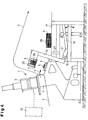
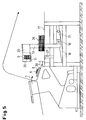
- the articles are closed when the tools are closed 1 to 3, these are cups 5 and, in the embodiment according to FIGS. 4 to 7, cover 6 - molded and punched.
- the lower tool 4 is pivoted in the arrow direction 7 into a stacking position and the articles (cup 5 or lid 6) are placed on a lower stacking plate 8 of a stacking and article counting device 9 connected downstream of the thermoforming machine 1.
- the inclined position of the thermoforming machine 1 with an inclination of approximately 10 ° to the floor allows the finished articles to be stacked almost vertically out of the lower tool 4 into the lower stacking plate 8.
- thermoforming machine 1 is connected to a higher-level programmable controller 10, shown only schematically as a black box, and as soon as the number of items selected via the controller 10 in the lower stacking plate 8 has been reached, a complementary upper stacking plate 11 is lowered and takes over corresponding article rods 12 from nesting Bechem 5; by lifting the upper stacking plate 11, the article rods 12 come free from the lower stacking plate 8, as shown in FIG. 1.
- a higher-level programmable controller 10 shown only schematically as a black box
- the upper stacking plate 11 can be raised and lowered on a swivel arm 13 which is mounted in a stacking device frame 15 which is movable on a base frame 14 and can be pivoted about a horizontal axis of rotation 16 (cf. FIG. 8, in particular FIG. 9).
- the swivel arm 13 is moved from its transfer position shown in FIG. 1 into the push-off position shown in FIG. 2 and at the same time about its axis of rotation or its pivot point 16 into a horizontal position Position swiveled.
- the swivel arm 13 is guided on the link rod 18 with guide rollers 22 carried by a slide 21; the slider 21 is rotatably supported in the swivel arm 13 by means of a pin 23 (cf. FIG. 9).
- the slide 21 can therefore pivot relatively during the movement of the swivel arm 13 in a kinematic relationship to it until it assumes the position shown in the end position according to FIG. 2.
- a movable pusher 24 is used, which pushes the article rods 12 through the cavities or openings in the upper stacking plate 11 onto the downstream storage tray 17.
- the upper stacking plate 11 arranged on the swivel arm 13 via a self-supporting crosshead 25 has been moved from its upper position in FIG. 1 on the swivel arm 13 into a position approximated to the pusher 24.
- the swivel arm 13 moves back after stacking the article rods 12 into the operating position shown in FIG. 1, the movement sequences are reversed accordingly.
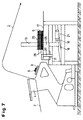
- the crosshead 25 is lowered with the lower stacking plate 11 until the article rods 26 which have been taken over are placed on an intermediate storage area in the form of finger plates 27 arranged in the stroke path, as shown in FIG. 6; 6, the crosshead 25 with the lower stacking plate 11 is then lowered further so that a pusher 28 can press the article rods 26, which are temporarily stored on the storage surface of the finger plates 27, onto the article rods 26 already present on the storage plate 17 from previous stacking processes, as shown in Fig. 7.
- the swivel arm 13 is then moved back into the starting position according to FIG. 4 with the opposite sequence of movements.
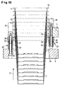
- Both the upper and the lower stacking plates 8 and 11 are provided with lifters 30 assigned to the stacking plate openings or cavities 29 (cf. FIG. 10), as in the left half of FIG. 10 for the lower stacking plate 8 and in the right Half of FIG. 10 shown for the upper stacking plate 11 for taking over cups 5.
- the lifters 30 are designed as automatic article retention elements; they consist of an elastic, resilient material and expand in a funnel-like manner according to FIG. 11 in the stacking direction 31 (cf. FIG. 10).
- a tubular sleeve 32 is provided with longitudinal slots 34 extending from its enlarged upper end to a cylindrical sleeve collar 33, which makes it possible, on the one hand, to provide a plurality of lifting lamellae 35 which are flared outwards and, on the other hand, to distribute a few over the circumference Pipe webs 36 - three webs in the exemplary embodiment (cf. the top view in FIG. 11) - in an unchanged vertical orientation, ie without exposing them to the outside.
- the lifters 30 are placed on stacking rods 37 and 38 of the lower and upper stacking plates 8 and 11 on threaded bolts 39 screwed into them, these being closely enclosed by the cylindrical sleeve collar 33 and the tube webs 36, and by tightening the threaded bolts 39 the respective stacking plates 8, 11 set.
- cups 5 their collars 40 come into contact with the lifting slats 35 facing them when they are introduced in the push-in direction 31, which, due to their elasticity, dodge in the direction of arrow 42 in the direction of arrow 42 shown in the longitudinal section of FIG.
Landscapes
- Engineering & Computer Science (AREA)
- Mechanical Engineering (AREA)
- Stacking Of Articles And Auxiliary Devices (AREA)
- Auxiliary Devices For And Details Of Packaging Control (AREA)
- Pile Receivers (AREA)
Applications Claiming Priority (2)
| Application Number | Priority Date | Filing Date | Title |
|---|---|---|---|
| DE29802318U | 1998-02-11 | ||
| DE29802318U DE29802318U1 (de) | 1998-02-11 | 1998-02-11 | Stapelvorrichtung für eine Thermoformmaschine |
Publications (3)
| Publication Number | Publication Date |
|---|---|
| EP0955150A2 true EP0955150A2 (fr) | 1999-11-10 |
| EP0955150A3 EP0955150A3 (fr) | 2001-10-17 |
| EP0955150B1 EP0955150B1 (fr) | 2003-04-09 |
Family
ID=8052502
Family Applications (1)
| Application Number | Title | Priority Date | Filing Date |
|---|---|---|---|
| EP99101898A Expired - Lifetime EP0955150B1 (fr) | 1998-02-11 | 1999-01-29 | Dispositif d'empilage pour une machine de thermoformage |
Country Status (4)
| Country | Link |
|---|---|
| US (1) | US6241457B1 (fr) |
| EP (1) | EP0955150B1 (fr) |
| AT (1) | ATE236779T1 (fr) |
| DE (2) | DE29802318U1 (fr) |
Cited By (3)
| Publication number | Priority date | Publication date | Assignee | Title |
|---|---|---|---|---|
| EP1122196A1 (fr) * | 2000-02-02 | 2001-08-08 | Gabler Maschinenbau GmbH | Machine de thermoformage |
| EP1201574A1 (fr) * | 2000-10-25 | 2002-05-02 | Adolf Illig Maschinenbau GmbH & Co | Procédé et dispostif pour empiler des pièces en matière thermoplastique |
| US6851920B2 (en) | 2000-10-25 | 2005-02-08 | Adolf Illig Maschinenbau Gmbh & Co. | Method for stacking parts comprising thermoplastic plastic, and apparatus for executing the method |
Families Citing this family (16)
| Publication number | Priority date | Publication date | Assignee | Title |
|---|---|---|---|---|
| DE19848628C2 (de) * | 1998-10-22 | 2002-09-12 | Gabler Gmbh Maschbau | Verfahren zum Betreiben einer Thermoformmaschine |
| DE19848627B4 (de) | 1998-10-22 | 2004-12-23 | Gabler Maschinenbau Gmbh | Stapelvorrichtung für eine Thermoformvorrichtung |
| DE29818791U1 (de) * | 1998-10-22 | 2000-03-02 | Gabler Maschinenbau GmbH, 23568 Lübeck | Thermoformmaschine |
| DE19852359C1 (de) * | 1998-11-13 | 2000-08-31 | Illig Maschinenbau Adolf | Vorrichtung zum Aufnehmen und Stapeln von Behältern aus thermoplastischem Kunststoff |
| DE19933355C1 (de) * | 1999-07-16 | 2001-03-15 | Illig Maschinenbau Adolf | Verfahren zum Stapeln von Behältern aus thermoplastischem Kunststoff und Vorrichtung zur Durchführung des Verfahrens |
| DE19933354C1 (de) * | 1999-07-16 | 2001-03-15 | Illig Maschinenbau Adolf | Verfahren zum Stapeln von Behältern aus thermoplastischem Kunststoff und Vorrichtung zur Durchführung des Verfahrens |
| DE10044228C2 (de) * | 2000-09-07 | 2002-11-28 | Illig Maschinenbau Adolf | Verfahren zum Stapeln von Behältern aus thermoplastischem Kunststoff |
| US6619486B1 (en) | 2002-03-25 | 2003-09-16 | Carlos J. Veloso | Flipper/catcher integrated with guide pin for up-stacking of die-cut thermoformed parts |
| US20040086370A1 (en) * | 2002-10-31 | 2004-05-06 | Randy Golden | System and method for stacking a predeterminded number of nestable objects |
| US6918737B2 (en) * | 2002-10-31 | 2005-07-19 | Solo Cup Company | System and method for stacking a predetermined number of nestable objects |
| US7318306B1 (en) * | 2006-08-14 | 2008-01-15 | Rennco Llc | Packaging method for packaging containers and lids |
| US8002102B2 (en) * | 2007-10-23 | 2011-08-23 | Irwin Jere F | Apparatus for orienting stacks of trimmed molded articles and method |
| EP2860017B1 (fr) | 2013-10-10 | 2017-01-11 | Gabler Thermoform GmbH & Co. KG | Machine de thermoformage |
| DE102018009994A1 (de) * | 2018-12-19 | 2020-06-25 | Illig Maschinenbau Gmbh & Co. Kg | Vorrichtung und Verfahren zum Bewegen von Formteilstapeln aus Formteilen |
| US11884437B2 (en) | 2021-08-10 | 2024-01-30 | Rennco Llc | Packaging machine and apparatus and method for feeding cups for packaging |
| CN115092461B (zh) * | 2022-07-07 | 2025-07-04 | 嘉兴恒匠智能技术有限公司 | 一种承托输送生产线及其承托输送方法 |
Family Cites Families (18)
| Publication number | Priority date | Publication date | Assignee | Title |
|---|---|---|---|---|
| US3499063A (en) * | 1966-12-27 | 1970-03-03 | Owens Illinois Inc | Apparatus and method for collecting molded articles |
| US3802819A (en) * | 1970-11-12 | 1974-04-09 | Myron J Greenfield | Thermoforming machine with articles trimmed in-place |
| US3759303A (en) * | 1971-06-09 | 1973-09-18 | Compact Ind | Cup handling apparatus |
| BE777899A (fr) * | 1972-01-11 | 1972-07-11 | Leenaards Antoine | Magasin de palettiseur ou de depalettiseur. |
| DE2517981A1 (de) * | 1975-04-23 | 1976-11-04 | Illig Maschinenbau Adolf | Verfahren und vorrichtung zur herstellung von artikeln aus thermoplastischer kunststoffolie |
| US4054212A (en) * | 1976-01-28 | 1977-10-18 | Owens-Illinois, Inc. | Cup dispensing apparatus and method |
| DE3346628C2 (de) | 1983-12-23 | 1986-03-27 | Adolf Illig Maschinenbau Gmbh & Co, 7100 Heilbronn | Vorrichtung zum Formen, Stanzen und Stapeln von tiefgezogenen Teilen aus thermoplastischem Kunststoff |
| GB2142272B (en) * | 1983-05-28 | 1986-04-23 | Illig Maschinenbau Adolf | Moulding apparatus |
| US4805758A (en) * | 1987-07-08 | 1989-02-21 | Van Dam Machine Corporation | Crossed turret cup feeder |
| US5273167A (en) * | 1989-03-13 | 1993-12-28 | Franz Haas Waffelmaschinen Industriegesellschaft M.B.H. | Apparatus for stacking individual one piece receptacles |
| US5234313A (en) * | 1990-10-31 | 1993-08-10 | Mobil Oil Corporation | Method for automatically counting and stacking trimmed molded articles |
| US5122029A (en) * | 1990-10-31 | 1992-06-16 | Mobil Oil Corporation | Apparatus and method for automatically counting and stacking trimmed molded articles |
| DK166721B1 (da) * | 1991-04-23 | 1993-07-05 | Bryde Hansen Bent | Maskine til stabling af baegerformede beholdere |
| DE4119534A1 (de) * | 1991-06-13 | 1992-12-17 | Windmoeller & Hoelscher | Vorrichtung zum stapeln von flachen gegenstaenden |
| ES2131292T3 (es) * | 1995-01-20 | 1999-07-16 | Cms Spa | Maquina para la recogida de vasos usados. |
| DE19503039B4 (de) * | 1995-02-01 | 2004-04-29 | Tetra Laval Holdings & Finance S.A. | Vorrichtung zur Herstellung eines Stapels von ineinandergesteckten, becherförmigen Gefäßen |
| DE19509057C2 (de) * | 1995-03-14 | 1997-05-22 | Illig Maschinenbau Adolf | Vorrichtung zum Überführen und Stapeln von aus einer thermoplastischen Kunststoffolie tiefgezogenen und ausgestanzten Behältern |
| US5704194A (en) * | 1996-02-14 | 1998-01-06 | Fleming Printing Company | Process and apparatus for applying wrapped packages to cups |
-
1998
- 1998-02-11 DE DE29802318U patent/DE29802318U1/de not_active Expired - Lifetime
-
1999
- 1999-01-29 DE DE59904916T patent/DE59904916D1/de not_active Expired - Lifetime
- 1999-01-29 AT AT99101898T patent/ATE236779T1/de active
- 1999-01-29 EP EP99101898A patent/EP0955150B1/fr not_active Expired - Lifetime
- 1999-02-09 US US09/248,085 patent/US6241457B1/en not_active Expired - Lifetime
Cited By (3)
| Publication number | Priority date | Publication date | Assignee | Title |
|---|---|---|---|---|
| EP1122196A1 (fr) * | 2000-02-02 | 2001-08-08 | Gabler Maschinenbau GmbH | Machine de thermoformage |
| EP1201574A1 (fr) * | 2000-10-25 | 2002-05-02 | Adolf Illig Maschinenbau GmbH & Co | Procédé et dispostif pour empiler des pièces en matière thermoplastique |
| US6851920B2 (en) | 2000-10-25 | 2005-02-08 | Adolf Illig Maschinenbau Gmbh & Co. | Method for stacking parts comprising thermoplastic plastic, and apparatus for executing the method |
Also Published As
| Publication number | Publication date |
|---|---|
| EP0955150B1 (fr) | 2003-04-09 |
| DE59904916D1 (de) | 2003-05-15 |
| EP0955150A3 (fr) | 2001-10-17 |
| ATE236779T1 (de) | 2003-04-15 |
| DE29802318U1 (de) | 1998-05-07 |
| US6241457B1 (en) | 2001-06-05 |
Similar Documents
| Publication | Publication Date | Title |
|---|---|---|
| EP0955150B1 (fr) | Dispositif d'empilage pour une machine de thermoformage | |
| DE3439660C2 (fr) | ||
| DE4224009A1 (de) | Verfahren und vorrichtung zur warmformung und stapelung von hohlen gegenstaenden mit boden aus einem kunststoffband | |
| DE4030833C2 (fr) | ||
| DE2141672A1 (de) | Vorrichtung für die Entformung und die Handhabung von Hohlkörpern aus Kunststoffmaterial | |
| DE2714352B2 (de) | Vorrichtung zum selbsttätigen Ausziehen von Stapeln von fertigen, aus einer Kunststoffolie warmgeformten Hohlgegenständen aus einer Stapelstation | |
| DE19804876B4 (de) | Verfahren und Einrichtung zur Wärmeformung und Dekorbandanbringung | |
| EP0296302B1 (fr) | Dispositif pour l'application d'étiquettes autocollantes sur la surface extérieure de récipients en matière plastique obtenus par thermoformage | |
| EP0995582B1 (fr) | Machine de thermoformage | |
| DE10303726B3 (de) | Vorrichtung zum Einsetzen von Stielen in Formen zum Herstellung von Stielkonfekt | |
| DE3103149A1 (de) | Automatische maschine zum kontinuierlichen abpacken von produkten | |
| DE2620788C2 (de) | Blasformmaschine | |
| EP3241443B1 (fr) | Machine et procédé de fabrication de saucisses enroulées | |
| CH631527A5 (de) | Verfahren zum herstellen von schraubenfedern und maschine zur durchfuehrung des verfahrens. | |
| DE2166939C3 (de) | Maschinelle Einrichtung zum Herstellen von Weichkäse | |
| DE4134746C2 (de) | Verfahren und Vorrichtung zum Stapeln gefalteter Wäschestücke | |
| EP0995583B1 (fr) | Machine de thermoformage | |
| DE102021112172B4 (de) | Vorrichtung zum Ausbrechen und Stapeln von Formteilen und Verfahren zum Umbau einer Stapelrichtung einer Vorrichtung zum Ausbrechen und Stapeln von Formteilen | |
| DE3226841A1 (de) | Verfahren zum herstellen von behaeltern aus thermoplastischer kunststoffolie und vorrichtung zur durchfuehrung des verfahrens | |
| DE3012289A1 (de) | Vorrichtung zur uebergabe von strangbroten | |
| DE2048505A1 (en) | Dough goods prodn machine - for moulding and baking esp wafers (ice cream cones) at reduced wastage | |
| DE2751953A1 (de) | Verfahren und vorrichtung zum einbringen gestapelter formteile in einen transportbehaelter | |
| CH666792A5 (de) | Verfahren und einrichtung fuer die formgebende bearbeitung von gemuesen. | |
| DE516325C (de) | Verfahren und Vorrichtung bei der Herstellung von Zuendholzschachteln zu ihrer Befoerderung von der Schachtelmaschine nach der Zusammenstossmaschine | |
| WO1998027820A1 (fr) | Machine pour le façonnage de bretzels |
Legal Events
| Date | Code | Title | Description |
|---|---|---|---|
| PUAI | Public reference made under article 153(3) epc to a published international application that has entered the european phase |
Free format text: ORIGINAL CODE: 0009012 |
|
| AK | Designated contracting states |
Kind code of ref document: A2 Designated state(s): AT BE CH CY DE DK ES FI FR GB GR IE IT LI LU MC NL PT SE Kind code of ref document: A2 Designated state(s): AT DE IT NL |
|
| AX | Request for extension of the european patent |
Free format text: AL;LT;LV;MK;RO;SI |
|
| PUAL | Search report despatched |
Free format text: ORIGINAL CODE: 0009013 |
|
| AK | Designated contracting states |
Kind code of ref document: A3 Designated state(s): AT BE CH CY DE DK ES FI FR GB GR IE IT LI LU MC NL PT SE |
|
| AX | Request for extension of the european patent |
Free format text: AL;LT;LV;MK;RO;SI |
|
| 17P | Request for examination filed |
Effective date: 20020413 |
|
| AKX | Designation fees paid |
Free format text: AT DE IT NL |
|
| GRAH | Despatch of communication of intention to grant a patent |
Free format text: ORIGINAL CODE: EPIDOS IGRA |
|
| GRAH | Despatch of communication of intention to grant a patent |
Free format text: ORIGINAL CODE: EPIDOS IGRA |
|
| GRAA | (expected) grant |
Free format text: ORIGINAL CODE: 0009210 |
|
| AK | Designated contracting states |
Designated state(s): AT DE IT NL |
|
| PG25 | Lapsed in a contracting state [announced via postgrant information from national office to epo] |
Ref country code: NL Free format text: LAPSE BECAUSE OF FAILURE TO SUBMIT A TRANSLATION OF THE DESCRIPTION OR TO PAY THE FEE WITHIN THE PRESCRIBED TIME-LIMIT Effective date: 20030409 Ref country code: IT Free format text: LAPSE BECAUSE OF FAILURE TO SUBMIT A TRANSLATION OF THE DESCRIPTION OR TO PAY THE FEE WITHIN THE PRESCRIBED TIME-LIMIT;WARNING: LAPSES OF ITALIAN PATENTS WITH EFFECTIVE DATE BEFORE 2007 MAY HAVE OCCURRED AT ANY TIME BEFORE 2007. THE CORRECT EFFECTIVE DATE MAY BE DIFFERENT FROM THE ONE RECORDED. Effective date: 20030409 |
|
| NLV1 | Nl: lapsed or annulled due to failure to fulfill the requirements of art. 29p and 29m of the patents act | ||
| PLBE | No opposition filed within time limit |
Free format text: ORIGINAL CODE: 0009261 |
|
| STAA | Information on the status of an ep patent application or granted ep patent |
Free format text: STATUS: NO OPPOSITION FILED WITHIN TIME LIMIT |
|
| 26N | No opposition filed |
Effective date: 20040112 |
|
| PGFP | Annual fee paid to national office [announced via postgrant information from national office to epo] |
Ref country code: DE Payment date: 20180122 Year of fee payment: 20 |
|
| PGFP | Annual fee paid to national office [announced via postgrant information from national office to epo] |
Ref country code: AT Payment date: 20180122 Year of fee payment: 20 |
|
| REG | Reference to a national code |
Ref country code: DE Ref legal event code: R071 Ref document number: 59904916 Country of ref document: DE |
|
| REG | Reference to a national code |
Ref country code: AT Ref legal event code: MK07 Ref document number: 236779 Country of ref document: AT Kind code of ref document: T Effective date: 20190129 |