EP0955155A1 - Presse - Google Patents
Presse Download PDFInfo
- Publication number
- EP0955155A1 EP0955155A1 EP98108337A EP98108337A EP0955155A1 EP 0955155 A1 EP0955155 A1 EP 0955155A1 EP 98108337 A EP98108337 A EP 98108337A EP 98108337 A EP98108337 A EP 98108337A EP 0955155 A1 EP0955155 A1 EP 0955155A1
- Authority
- EP
- European Patent Office
- Prior art keywords
- eccentric
- press
- connecting rod
- ram
- press according
- Prior art date
- Legal status (The legal status is an assumption and is not a legal conclusion. Google has not performed a legal analysis and makes no representation as to the accuracy of the status listed.)
- Withdrawn
Links
- 238000005520 cutting process Methods 0.000 claims description 7
- 230000007246 mechanism Effects 0.000 abstract description 2
- 238000010276 construction Methods 0.000 description 11
- 238000000034 method Methods 0.000 description 5
- 230000002349 favourable effect Effects 0.000 description 2
- 230000006978 adaptation Effects 0.000 description 1
- 230000008094 contradictory effect Effects 0.000 description 1
- 230000008878 coupling Effects 0.000 description 1
- 238000010168 coupling process Methods 0.000 description 1
- 238000005859 coupling reaction Methods 0.000 description 1
- 230000000694 effects Effects 0.000 description 1
- 230000014509 gene expression Effects 0.000 description 1
- 238000003754 machining Methods 0.000 description 1
- 238000004519 manufacturing process Methods 0.000 description 1
- 239000000463 material Substances 0.000 description 1
- 238000012544 monitoring process Methods 0.000 description 1
- 238000009740 moulding (composite fabrication) Methods 0.000 description 1
- 238000004080 punching Methods 0.000 description 1
- 238000007493 shaping process Methods 0.000 description 1
- 125000006850 spacer group Chemical group 0.000 description 1
- 239000002699 waste material Substances 0.000 description 1
Images






Classifications
-
- B—PERFORMING OPERATIONS; TRANSPORTING
- B30—PRESSES
- B30B—PRESSES IN GENERAL
- B30B15/00—Details of, or accessories for, presses; Auxiliary measures in connection with pressing
- B30B15/04—Frames; Guides
- B30B15/041—Guides
-
- B—PERFORMING OPERATIONS; TRANSPORTING
- B30—PRESSES
- B30B—PRESSES IN GENERAL
- B30B1/00—Presses, using a press ram, characterised by the features of the drive therefor, pressure being transmitted directly, or through simple thrust or tension members only, to the press ram or platen
- B30B1/26—Presses, using a press ram, characterised by the features of the drive therefor, pressure being transmitted directly, or through simple thrust or tension members only, to the press ram or platen by cams, eccentrics, or cranks
-
- B—PERFORMING OPERATIONS; TRANSPORTING
- B30—PRESSES
- B30B—PRESSES IN GENERAL
- B30B15/00—Details of, or accessories for, presses; Auxiliary measures in connection with pressing
- B30B15/0029—Details of, or accessories for, presses; Auxiliary measures in connection with pressing means for adjusting the space between the press slide and the press table, i.e. the shut height
- B30B15/0035—Details of, or accessories for, presses; Auxiliary measures in connection with pressing means for adjusting the space between the press slide and the press table, i.e. the shut height using an adjustable connection between the press drive means and the press slide
-
- B—PERFORMING OPERATIONS; TRANSPORTING
- B30—PRESSES
- B30B—PRESSES IN GENERAL
- B30B15/00—Details of, or accessories for, presses; Auxiliary measures in connection with pressing
- B30B15/0064—Counterbalancing means for movable press elements
Definitions
- the invention relates to a press, in particular a cutting and forming press according to the features of the preamble of claim 1.
- Such presses have long been known for forming, cutting or punching workpieces.
- a ram which can be moved back and forth in a straight line in the press housing, is used to deform the workpieces.
- the press essentially consists of a press stand and an engine.
- the press is in particular a cutting or forming press.
- the press stand has a work area for receiving the workpiece to be deformed.
- a ram for reshaping the workpiece is slidably mounted in the work area.
- the engine has at least one eccentric shaft rotatable about an eccentric axis with an eccentric and at least one connecting rod.
- the connecting rod has a connecting rod foot which is connected directly or indirectly to the eccentric and a connecting rod head which is connected directly or indirectly to the tappet in an articulated manner.
- the ram can be displaced between a rest position and a working position in the work space of the press in order to deform a workpiece.
- the rest position corresponds to the top dead center of the vertical press axis and the working position corresponds to the bottom dead center of the ram.
- the at least one connecting rod and the eccentric are arranged and connected to the tappet in such a way that the distance between the connecting rod head and the eccentric axis is smaller in the working position (i.e. at the bottom dead center of the connecting rod) than in the rest position (where the connecting rod is at top dead center) ). This ensures that the course of the ram stroke is flatter in the area of the working position than in the area of the rest position. A slower forming of the workpieces with relatively high stroke rates is possible.
- the degree of flattening of the ram stroke is determined by the ratio ( ⁇ ) between the eccentric radius and the connecting rod length. According to the features of the invention, the ratio ⁇ is preferably large, i.e. if possible 0.5 or larger selected.
- the engine ie the eccentric, the connecting rod (s) and any connecting links are above the horizontal plane defined by the rest position of the ram arranged.
- Such an engine arranged above the work area leads to a number of advantages in the operation and design of the press.
- the formed parts or waste can simply be removed from the work area downwards.
- the space requirement of the press below the work table is small, which means smaller footprint and better usability of the press.
- space beneath the work table remains free for adding hydraulic cylinders or other means as a shaping aid and for manipulating the machined or machined workpiece.
- the engine is guided in the press stand in the direction of force application, whereby forces directed transversely to the direction of force application are supported.
- the ram can have one or more, preferably two or four pressure columns for exerting a force on the ram, which are guided laterally with guide means such as sliders in the press stand. Lateral engine forces are thus supported by means of the sliding pieces, which ensures that even with eccentric tappet loading by the tool, the pressure columns only act on the tappet with forces parallel to the direction in which the force is exerted. So there are no engine-related side forces on the ram.
- the direction of force is understood here and below to mean the direction of movement of the ram.
- the direction of movement of the ram is generally vertical.
- the lateral support of the pressure columns which advantageously takes place at the upper end of the pressure columns, means that the force is always transmitted vertically to the ram.
- the engine advantageously has one or more transverse yokes which connect the connecting rod to the pressure columns and / or the eccentric.
- the transverse yokes allow force to be exerted evenly with an eccentric shaft and a connecting rod on two pressure columns arranged side by side.
- the pressure columns can preferably be connected to the plunger by means of height-adjustable threaded spindles and with overload protection.
- the distance between the ram and the table top can be changed with the threaded spindles and adapted to the respective conditions.
- the eccentric shaft is arranged offset by a distance from the axis of symmetry of the engine.
- the setting the downward movement of the ram is slowed down as a whole, but in particular in the area of the bottom dead center. This favors the forming process.
- the upward movement of the ram takes place in a shorter time than with a centrally arranged eccentric shaft, so that the time lost during the working stroke is compensated for during the return stroke. This results in a given degree of deformation higher productivity of the parts to be produced.
- the eccentricity of the eccentric can be adjustable.
- the connecting rod is mounted on the eccentric and is articulated to the pressure columns via one or more transverse yoke (s).
- the cross yoke and the plunger can advantageously be designed such that the cross yoke is supported in the plunger. This measure practically prevents the ram from tipping over when the tool is eccentrically loaded.
- a transverse yoke on the eccentric and to connect it in an articulated manner to the pressure columns and to a connecting bracket connecting the pressure column by means of at least two, preferably four connecting rods.
- the connecting lug and the plunger can advantageously be designed such that the connecting lug is supported in the plunger. This measure also tilts the ram when the load is off-center avoided by the tool.
- the provision of four connecting rods can also be advantageous with a lower drive.
- connecting rods which connect a transverse yoke to the pressure columns, has very special advantages. Because the force is distributed over several connecting rods, preferably four connecting rods, they can be designed with a smaller connecting rod length than the known one and the connecting rods cannot be supported directly on the always relatively large eccentric diameter. This means that for a given ram stroke (which is defined by the eccentricity of the eccentric), a ratio of eccentric radius (lambda) to connecting rod length that is particularly favorable for the forming process can be selected. In particular for small-stroke presses up to around 400mm, despite the small Hunib, it is possible to choose the value Lambda so that a sufficiently flat curve of the ram movement can be achieved at bottom dead center.
- the lambda value for all embodiments of the invention is about 0.4 to 0.6. Arrangements with one or more connecting rods are conceivable for a ram stroke of more than 400 mm.
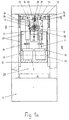
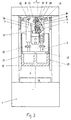
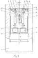
- the cutting and forming press shown in FIG. 1 in the rest position R has a frame for the press stand 1, which is stiffened at the front and rear by insertable transverse walls 27.
- a ram 2 is guided in the press stand 1 by means of guides 17.
- the cutting and forming press has an engine for generating a stroke movement of the ram.
- the engine essentially consists of an eccentric 24 on an eccentric shaft 3, a connecting rod 19 and transverse yoke plates 21.
- the eccentric shaft can be driven by means of known drive means.
- the press also has a working space 28 for receiving a workpiece to be deformed.
- the plunger 2 is slidably mounted in the guides in the working space 28 between a rest position R and a working position A.
- the work space 28 has a table top 18 on which the tool is placed.
- a connecting rod foot 31 of the connecting rod 19 is mounted on the eccentric 24.
- the connecting rod head 32 is seen from the eccentric shaft 3 and is arranged pointing away from the working space 28 of the press.
- the connecting rod head is articulated with a bolt 20 on the two transverse yoke plates 21.
- the transverse yoke plates 21 are articulated with bolts 22 to pressure columns 7.
- the pressure columns 7 are connected to the plunger 2 via threaded spindles 11 in the pressure columns 7 and via load limits 12.
- the plunger 2 defines a horizontal plane H in the rest position R.
- the engine i.e. in particular the eccentric 24, the connecting rod 19, the pressure columns 7 and the yoke plates 21 are arranged above the horizontal plane H.
- the engine is also designed such that, in the rest position R, the distance a between the eccentric axis 33 and the articulation point of the connecting rod head 32 is greater than in the working position (see FIG. 1b).
- the slowing down of the ram movement at bottom dead center is determined by the ratio between the eccentric radius r and the connecting rod length 1.
- the ratio lambda is approximately 0.5.
- the threaded spindles 11 have adjusting spindles 10, by means of which they can be rotated.
- the distance between the plunger 2 and the table top 18 can thus be changed or the be adapted to the respective conditions.
- the two threaded spindles 11 are coupled to one another, that is to say they rotate synchronously, which ensures parallel adjustment of the plunger 2.
- the lateral engine forces are supported by means of support flanges 13 at the upper end of the pressure columns 7 and adjustable sliding pieces 14, which are guided in guides 15.
- the connecting rod pulls to work.
- the support of the lateral engine forces by means of the sliding pieces 14 ensures that, even with eccentric tappet loading by the tool, the pressure columns 7 only act on the tappet 2 with vertical forces, so that no engine-related side forces act on the tappet 2.
- the ram 2 does not slide in the horizontal direction due to the guides, even when the load is off-center, which results in longer tool life.
- the purely mechanical engine enables simple and reliable coupling of the feed and any transfer devices. Tool monitoring and control are also easy.
- a mass balance 23 is arranged below the eccentric and the connecting rod.
- Fig. 1 is particularly suitable for presses with a relatively high ram stroke, in particular more than 400mm. With such high tappet strokes, the ratio of lambda 0.4 to 0.6 can also be achieved with a relatively large connecting rod.
- Fig. 1b the press from Fig. 1a is shown in the working position A.
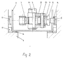
- Fig. 2 shows the embodiment of Fig. 1 in plan view and partially in section along the plane II - II of Fig. 1.
- the pressure columns 7, which exert a force on the plunger 2 are by means of support flanges 13 and sliders 14 in the side Engine guides 15 slidably mounted.
- the pressure columns 7 are connected in an articulated manner to the transverse yoke plates 21 by means of bolts 22.
- the transverse yoke plates 21 are in turn articulated to the connecting rod 19 via a bolt 20.
- the ram 2 is guided in the press stand 1 via ram guides 16, 17.
- the pressure columns 7 have two side parts in the area of the connection to the transverse yoke plates 21, which are held at a distance from one another by a spacer bush 29 arranged around the bolt 22.
- FIG. 3 shows a modified exemplary embodiment of the embodiment from FIG. 1.
- the eccentric shaft 3 is arranged offset by a distance e from the axis of symmetry S of the engine.
- e the distance from the axis of symmetry S of the engine.
- FIG. 4 shows a further exemplary embodiment of the first embodiment shown in FIG. 1.
- 4 is the Transverse yoke plate 25 additionally supported in the plunger 2. So that the cross-yoke plate can be fitted well into the ram, adjustment devices (not shown) are attached to the leg. This measure practically prevents the ram from tipping over when the tool is eccentrically loaded. Otherwise, the exemplary embodiment shown in FIG. 4 is identical to that shown in FIG. 1.
- FIG. 5 shows the embodiment from FIG. 4 in a top view and partly in section according to the plane II-II from FIG. 4.
- FIG. 5 shows how the transverse yoke plate 25 is supported with its end in the plunger 2.
- FIG. 6 shows a further exemplary embodiment of the first embodiment, which has a four-point support of the ram.
- two engines which are essentially identical, are arranged on the eccentric shaft 3 in the longitudinal direction thereof.
- the inclination shown in FIG. 3 and the support of the transverse yoke 25 shown in FIG. 4 in the plunger 2 can be used.
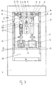
- the press also has a frame-shaped press stand which is stiffened at the front and rear by insertable transverse walls 27.
- a plunger 2 is guided by means of guides 16, 17 (see FIG. 8).
- the engine essentially consists of an eccentric 24 on an eccentric shaft 3, a yoke 4 and connecting rods 5.
- the yoke 4 is mounted on the eccentric 24.
- the connecting rods 5 are seen from the yoke 4, ie from the eccentric shaft 3 seen from the working space 28 of the press.
- the connecting rods are connected by means of a bolt 9 to a connecting bracket 6 and to the pressure columns 7.
- the bolts 9 transfer the workers to the pressure columns 7.
- the pressure columns 7 have threaded spindles 11 which are coupled to the plunger 2 via load limits 12.
- the threaded spindles 11 can be rotated and thus the ram distance 18 can be changed or adapted to the respective conditions.
- the threaded spindles 11 are coupled and therefore rotate synchronously. The parallel adjustment of the plunger 2 is thus ensured.
- the lateral engine forces are guided by means of support flanges 13 at the upper ends of the pressure columns 7 and by means of slide pieces 14 in guides 15 and are thus supported.
- bias cylinders 30 are provided, which prevent the thread play of the threaded spindle 11 in the pressure column 7.
- connection from the yoke 4 to the pressure columns 7 is made by means of four connecting rods, small pin diameters result and the connecting rods 5 can therefore also be made short.
- a value of the ratio ⁇ between the eccentric radius r and the connecting rod length l, which is between 0.4 and 0.6, can thus be achieved even with a relatively small working stroke of the ram 2.
- Fig. 8 shows the embodiment shown in Fig. 7 in plan view and partially in section.
- the connecting rods 5 are connected in an articulated manner via the bolts 9 to the pressure columns 7 and to a connecting bracket 6.
- the connecting strap 6 connects the two pressure columns 7 to one another with the bolts 9.
- FIG. 9 shows a modified exemplary embodiment of the second embodiment shown in FIG. 7, in which the eccentric shaft 3 is arranged offset by a distance e from the axis of symmetry S of the engine.
- the measure mentioned above also gives the advantage of greater productivity already described in FIG. 3.
- Fig. 10 shows a view of a further modified embodiment of the second embodiment in section.
- the connecting strap 6 is additionally supported in the plunger 2.
- the legs of the tab can be provided with adjustment devices, not shown, for adaptation to the plunger. 4, the tilting of the plunger 2 is practically prevented when the tool is eccentrically loaded.
- FIG. 11 shows the exemplary embodiment according to FIG. 10 along the sectional plane I - I.
- the pressure columns 7 and the connecting rods 5 are arranged within the two connecting straps 6, which are supported in the plunger 2 with an extended end.
- FIG. 12 shows a modified embodiment of the second embodiment with a four-point support of the ram.
- FIG. 12 essentially corresponds to FIG. 6. Also in this embodiment, setting (as shown in FIG. 9) and support of the compensation bracket (as shown in FIG. 10) are possible. This results in the ones already mentioned Advantages.
- FIG. 13 shows a view with two counter-rotating eccentric shafts 3.
- the sliding pieces 14 are loaded much less and this only when the ram is eccentrically loaded. If two tappet drives according to FIG. 13 are arranged one behind the other, a four-point drive of the tappet is also obtained, on which, even when the tappet 2 is eccentrically loaded, no horizontal forces caused by the engine also act.
- FIG. 14 shows a top view, partly in section, of the arrangement according to FIG. 13 with counter-rotating eccentric shafts 3.
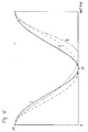
- Fig. 15 the stroke of the ram is shown over a work cycle of three different designs of eccentric presses.
- the solid line I shows the curve of a ram in a press according to the prior art. (The connecting rod presses to form). The speed of the ram (i.e. the slope of the stroke) is relatively high in the area of bottom dead center. Curve I is based on a press with an eccentric / connecting rod ratio of lambda of 0.2.
- Curve II shown in broken lines, shows the stroke course of a press with the features of the invention.
- the forming in the bottom dead center takes place when the connecting rod pulls. Thanks to the forming with a connecting rod under tension and thanks to an eccentric / connecting rod length ratio of lambda 0.5, the stroke curve is flattened in the area of the bottom dead center, which leads to better forming results.
- the dash-dotted curve III shows a press as in curve II with a set.
- the curve before the lower one Dead center is also flattened, whereas the ram quickly moves away from it after bottom dead center.
- the time of the entire cycle remains the same, but the forming speed is also reduced.
Landscapes
- Engineering & Computer Science (AREA)
- Mechanical Engineering (AREA)
- Press Drives And Press Lines (AREA)
Priority Applications (1)
| Application Number | Priority Date | Filing Date | Title |
|---|---|---|---|
| EP98108337A EP0955155A1 (fr) | 1998-05-07 | 1998-05-07 | Presse |
Applications Claiming Priority (1)
| Application Number | Priority Date | Filing Date | Title |
|---|---|---|---|
| EP98108337A EP0955155A1 (fr) | 1998-05-07 | 1998-05-07 | Presse |
Publications (1)
| Publication Number | Publication Date |
|---|---|
| EP0955155A1 true EP0955155A1 (fr) | 1999-11-10 |
Family
ID=8231893
Family Applications (1)
| Application Number | Title | Priority Date | Filing Date |
|---|---|---|---|
| EP98108337A Withdrawn EP0955155A1 (fr) | 1998-05-07 | 1998-05-07 | Presse |
Country Status (1)
| Country | Link |
|---|---|
| EP (1) | EP0955155A1 (fr) |
Cited By (1)
| Publication number | Priority date | Publication date | Assignee | Title |
|---|---|---|---|---|
| US7152523B2 (en) | 2000-06-26 | 2006-12-26 | Aida Engineering Co., Ltd. | Press machine |
Citations (6)
| Publication number | Priority date | Publication date | Assignee | Title |
|---|---|---|---|---|
| GB487089A (en) * | 1937-04-17 | 1938-06-15 | Walter Samuel Wilkins | Improvements in power presses |
| FR1019509A (fr) * | 1950-04-20 | 1953-01-22 | Schuler L Ag | Presse |
| GB754229A (en) * | 1954-02-10 | 1956-08-08 | Us Industries Inc | Improvements in or relating to forging presses |
| FR2401017A1 (fr) * | 1977-08-25 | 1979-03-23 | Inadex Sa | Presse pour travaux d'automatisme ou de matricage |
| EP0551919A1 (fr) * | 1992-01-17 | 1993-07-21 | Werkzeugmaschinen GmbH Zeulenroda | Dispositif d'équilibrage dynamique, réglable, synchronisé pour presse ou poinçonneuse à excentrique avec réglage de la course automatique |
| EP0628403A1 (fr) * | 1993-06-04 | 1994-12-14 | Bruderer Ag | Presse excentrique poinçonneuse à arbre unique et coulisseau avec quatre points de raccordement |
-
1998
- 1998-05-07 EP EP98108337A patent/EP0955155A1/fr not_active Withdrawn
Patent Citations (6)
| Publication number | Priority date | Publication date | Assignee | Title |
|---|---|---|---|---|
| GB487089A (en) * | 1937-04-17 | 1938-06-15 | Walter Samuel Wilkins | Improvements in power presses |
| FR1019509A (fr) * | 1950-04-20 | 1953-01-22 | Schuler L Ag | Presse |
| GB754229A (en) * | 1954-02-10 | 1956-08-08 | Us Industries Inc | Improvements in or relating to forging presses |
| FR2401017A1 (fr) * | 1977-08-25 | 1979-03-23 | Inadex Sa | Presse pour travaux d'automatisme ou de matricage |
| EP0551919A1 (fr) * | 1992-01-17 | 1993-07-21 | Werkzeugmaschinen GmbH Zeulenroda | Dispositif d'équilibrage dynamique, réglable, synchronisé pour presse ou poinçonneuse à excentrique avec réglage de la course automatique |
| EP0628403A1 (fr) * | 1993-06-04 | 1994-12-14 | Bruderer Ag | Presse excentrique poinçonneuse à arbre unique et coulisseau avec quatre points de raccordement |
Cited By (1)
| Publication number | Priority date | Publication date | Assignee | Title |
|---|---|---|---|---|
| US7152523B2 (en) | 2000-06-26 | 2006-12-26 | Aida Engineering Co., Ltd. | Press machine |
Similar Documents
| Publication | Publication Date | Title |
|---|---|---|
| DE19913710B4 (de) | Antriebsvorrichtung für ein Gleitstück einer Kniehebelpresse | |
| DE102007056266B4 (de) | Presse | |
| EP0543772A1 (fr) | Presse | |
| DE1935998A1 (de) | Bandfilterpresse | |
| DE10053690B4 (de) | Presse mit Linearschlitten | |
| EP2127772A2 (fr) | Dispositif de formage | |
| EP3160726B1 (fr) | Presse à châssis en c, améliorée | |
| DE2131013C2 (de) | Ziehpresse | |
| DE2748462A1 (de) | Presse zur herstellung keramischer oder feuerfester fliesen oder kacheln | |
| AT507110B1 (de) | Presse zum umformen von material | |
| EP1648626B1 (fr) | Dispositif de laminage | |
| EP0953438A1 (fr) | Presse à estamper, en particulier presse rapide | |
| DE4425565C2 (de) | Mehrsäulenpresse | |
| DE102009015210A1 (de) | Pressvorrichtung und Verfahren zur Herstellung von Presslingen aus Lignin- und/oder cellulosehaltigen Bestandteilen | |
| DE3002039A1 (de) | Stehende hydraulische gesenkpresse | |
| EP1350582A2 (fr) | Mécanisme d'éjection au côté matrice dans une presse à un ou multiples étages | |
| EP0576964B1 (fr) | Presse à découper et à déformer avec un ou plusieurs vérins d'entraînement et à genouillère | |
| DE3100093A1 (de) | Vorrichtung zur begrenzung des ausbauwiderstandes eines hydraulischen ausbauschildes | |
| DE69014382T2 (de) | Vorrichtung zum Verdichten und Schneiden von Abfällen, insbesondere Schrott. | |
| DE2915966A1 (de) | Messvorrichtung fuer die presskraft einer presse | |
| DE4303017C2 (de) | Kniehebelpresse | |
| DE2424802C3 (de) | Presse zum Herstellen von Formungen aus pulverförmigen oder körnigen Werkstoffen | |
| DE8027473U1 (de) | Brikettpresse | |
| DE4129029A1 (de) | Flachbett-stanzmaschine zum stanzen von flachen gegenstaenden, insbesondere boegen aus papier, pappe oder dergleichen | |
| DE1502200A1 (de) | Presse mit einem feststehenden Pressenholm und einem beweglichen Pressenholm sowie hydraulischem Antrieb |
Legal Events
| Date | Code | Title | Description |
|---|---|---|---|
| PUAI | Public reference made under article 153(3) epc to a published international application that has entered the european phase |
Free format text: ORIGINAL CODE: 0009012 |
|
| AK | Designated contracting states |
Kind code of ref document: A1 Designated state(s): AT BE CH CY DE DK ES FI FR GB GR IE IT LI LU MC NL PT SE |
|
| AX | Request for extension of the european patent |
Free format text: AL;LT;LV;MK;RO;SI |
|
| AKX | Designation fees paid | ||
| REG | Reference to a national code |
Ref country code: DE Ref legal event code: 8566 |
|
| STAA | Information on the status of an ep patent application or granted ep patent |
Free format text: STATUS: THE APPLICATION IS DEEMED TO BE WITHDRAWN |
|
| 18D | Application deemed to be withdrawn |
Effective date: 20000511 |