EP0955187A1 - Unabhängige Radaufhängung, insbesondere für Raupenfahrzeuge - Google Patents
Unabhängige Radaufhängung, insbesondere für Raupenfahrzeuge Download PDFInfo
- Publication number
- EP0955187A1 EP0955187A1 EP98830279A EP98830279A EP0955187A1 EP 0955187 A1 EP0955187 A1 EP 0955187A1 EP 98830279 A EP98830279 A EP 98830279A EP 98830279 A EP98830279 A EP 98830279A EP 0955187 A1 EP0955187 A1 EP 0955187A1
- Authority
- EP
- European Patent Office
- Prior art keywords
- suspension system
- independent suspension
- elastic element
- comprised
- axle
- Prior art date
- Legal status (The legal status is an assumption and is not a legal conclusion. Google has not performed a legal analysis and makes no representation as to the accuracy of the status listed.)
- Withdrawn
Links
Images

Classifications
-
- B—PERFORMING OPERATIONS; TRANSPORTING
- B60—VEHICLES IN GENERAL
- B60G—VEHICLE SUSPENSION ARRANGEMENTS
- B60G5/00—Resilient suspensions for a set of tandem wheels or axles having interrelated movements
- B60G5/04—Resilient suspensions for a set of tandem wheels or axles having interrelated movements with two or more pivoted arms, the movements of which are resiliently interrelated, e.g. the arms being rigid
Definitions
- the present invention relates to independent suspensions, particularly for tracked vehicles.
- the invention concerns a device of the above kind suitable to realise a suspension system allowing to obtain an optimum suspension action, particularly in case of particularly steep and disarranged grounds.
- Main object of the present invention is that of making the suspension of the "rocking arm” kind that are often employed on tracked vehicles and like.
- this kind of suspensions is realised in such a way to allow to a pair of wheels to rotate only about an horizontal axis, but without allowing the deformation of the whole rocking arm, so that a suitable absorption of the shocks due to the ground upward projecting bumps.
- Another object of the present invention is that of realising a suspension system allowing to use a rigid frame, without the need of using an articulated frame.
- Still another object of the present invention is that of realising a suspension system allowing to obtain a large bump position or relevant movement of one wheel with respect to the other.
- the solution proposed according to the present invention allows to distribute the load between the two wheels.
- suspension system according to the present invention when employed on not-tracked vehicles, also allows to vary the height.
- an independent suspension system particularly for tracked vehicles, for a pair of wheel axles, comprising two swinging arms, one for each axle, fixedly connected at one end with at least one rotation axis passing through the vehicle frame, and at the other end coupled with said axle, support elements, fixedly coupled with said at least one rotation axis and on which an elastic element is coupled, said elastic element acting on both the swinging arms.
- two distinct rotation axles are provided, said axles passing through the frame.
- the coupling between the swinging arm and the axle is realised by hubs provided with bearings.
- upper and/or lower end of the stroke element scan be provided to limit the oscillation of the swinging axis, interfering with end of the stroke stoppers fixedly connected with said swinging arms.
- said elastic element can be comprised of a hydraulic cylinder, eventually provided with a hydropneumatic accumulator.
- a throttling element can be provided in parallel with said hydraulic cylinder.
- said elastic element can be comprised of a pneumatic cylinder, eventually provided with a hydropneumatic accumulator.
- said elastic element can be comprised of a cylinder within which elastic means with adjustable hardness are provided.
- said elastic element can be comprised of a spring.
- two pairs of support elements can be provided.
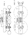
- the suspension according to the invention provides two crank arms 1, fixedly coupled on one end to rotation axes 2, and on the other side supporting the driving wheels 3 by hubs provided with bearings, which are not part of the invention.
- Supports 4 are fixedly coupled to the axis 2 on which a hydraulic cylinder 5 is constrained by pins 6.
- Said rotation axes 2 can oscillate on spherical supports 7 which constrained to the frame 8 by a support bushing 9.
- a hydropneumatic accumulator 10 connected to the piston 5 in such a way that the piston 5 is no more longitudinally rigid but instead can be axially deformed under the action of outer forces.
- an hydraulic throttling element provided in parallel, can allow to the piston to behave as viscoelastic element and not only as elastic element.
- Axes 2 are constrained to the frame with a rotoidal realised by a pair of coaxial spherical articulated joints.
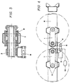
- each arm 1 has two supports 4 for the elastic elements and not only one, and consequently two are the elastic elements 5, indicated in an illustrative but not limitative way as hydraulic pistons, which will work one under traction and the other one under compression.
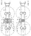
- solution of figure 6 will provide a distance between the two rotation axis 2 substantially null, so that the two rotation axis substantially coincide. It generally involves the lengthening of the two arms 1 and a different design of the two supports 4, but for any other respect the operation of the suspension is unchanged.
- hydraulic cylinder 5 is replaced by any other kind of elastic element having a sufficient rigidity, such as a steel spring or a pneumatic cylinder having suitable dimensions.
Landscapes
- Engineering & Computer Science (AREA)
- Mechanical Engineering (AREA)
- Vehicle Body Suspensions (AREA)
Priority Applications (1)
| Application Number | Priority Date | Filing Date | Title |
|---|---|---|---|
| EP98830279A EP0955187A1 (de) | 1998-05-08 | 1998-05-08 | Unabhängige Radaufhängung, insbesondere für Raupenfahrzeuge |
Applications Claiming Priority (1)
| Application Number | Priority Date | Filing Date | Title |
|---|---|---|---|
| EP98830279A EP0955187A1 (de) | 1998-05-08 | 1998-05-08 | Unabhängige Radaufhängung, insbesondere für Raupenfahrzeuge |
Publications (1)
| Publication Number | Publication Date |
|---|---|
| EP0955187A1 true EP0955187A1 (de) | 1999-11-10 |
Family
ID=8236645
Family Applications (1)
| Application Number | Title | Priority Date | Filing Date |
|---|---|---|---|
| EP98830279A Withdrawn EP0955187A1 (de) | 1998-05-08 | 1998-05-08 | Unabhängige Radaufhängung, insbesondere für Raupenfahrzeuge |
Country Status (1)
| Country | Link |
|---|---|
| EP (1) | EP0955187A1 (de) |
Cited By (5)
| Publication number | Priority date | Publication date | Assignee | Title |
|---|---|---|---|---|
| US6986519B2 (en) | 1997-01-31 | 2006-01-17 | Aloha, Llc | Low profile chassis and suspension |
| US7108271B2 (en) | 1997-01-31 | 2006-09-19 | Earl Dallas Smith | Axleless vehicle suspension system |
| US7425005B2 (en) | 2003-10-24 | 2008-09-16 | Aloha, Llc | Suspensions for low floor vehicles |
| US7559400B2 (en) | 1997-01-31 | 2009-07-14 | Aloha, Llc | Low profile chassis and suspension |
| CN104875570A (zh) * | 2015-06-10 | 2015-09-02 | 河北览众专用汽车制造有限公司 | 一种汽车及挂车底盘用机械复合式独立悬架 |
Citations (4)
| Publication number | Priority date | Publication date | Assignee | Title |
|---|---|---|---|---|
| DE467309C (de) * | 1928-10-23 | Fried Krupp Akt Ges | Radgestell fuer Fahrzeuge | |
| US3752498A (en) * | 1971-10-07 | 1973-08-14 | Gen Motors Corp | Oleo-pneumatic suspension assembly |
| US4030738A (en) * | 1976-07-19 | 1977-06-21 | Willetts Elwood H | Tandem axle vehicle suspension system |
| EP0149262A2 (de) * | 1984-01-16 | 1985-07-24 | Roberto Perlini | Fahrzeugaufhängung mit Elementen verschiedener Elastizität |
-
1998
- 1998-05-08 EP EP98830279A patent/EP0955187A1/de not_active Withdrawn
Patent Citations (4)
| Publication number | Priority date | Publication date | Assignee | Title |
|---|---|---|---|---|
| DE467309C (de) * | 1928-10-23 | Fried Krupp Akt Ges | Radgestell fuer Fahrzeuge | |
| US3752498A (en) * | 1971-10-07 | 1973-08-14 | Gen Motors Corp | Oleo-pneumatic suspension assembly |
| US4030738A (en) * | 1976-07-19 | 1977-06-21 | Willetts Elwood H | Tandem axle vehicle suspension system |
| EP0149262A2 (de) * | 1984-01-16 | 1985-07-24 | Roberto Perlini | Fahrzeugaufhängung mit Elementen verschiedener Elastizität |
Cited By (7)
| Publication number | Priority date | Publication date | Assignee | Title |
|---|---|---|---|---|
| US6986519B2 (en) | 1997-01-31 | 2006-01-17 | Aloha, Llc | Low profile chassis and suspension |
| US7108271B2 (en) | 1997-01-31 | 2006-09-19 | Earl Dallas Smith | Axleless vehicle suspension system |
| US7559400B2 (en) | 1997-01-31 | 2009-07-14 | Aloha, Llc | Low profile chassis and suspension |
| US7425005B2 (en) | 2003-10-24 | 2008-09-16 | Aloha, Llc | Suspensions for low floor vehicles |
| US7703781B2 (en) | 2003-10-24 | 2010-04-27 | Aloha, Llc | Suspensions for low floor vehicle |
| CN104875570A (zh) * | 2015-06-10 | 2015-09-02 | 河北览众专用汽车制造有限公司 | 一种汽车及挂车底盘用机械复合式独立悬架 |
| CN104875570B (zh) * | 2015-06-10 | 2017-03-22 | 河北览众专用汽车制造有限公司 | 一种汽车底盘用机械复合式独立悬架 |
Similar Documents
| Publication | Publication Date | Title |
|---|---|---|
| US5879016A (en) | Pivoting spring-mounted axle suspension | |
| EP2727803B1 (de) | Raupenaufhängung | |
| US4778198A (en) | Apparatus for compensating transverse forces in automotive struts | |
| US6523844B2 (en) | Suspended axle of the articulated-connection type for industrial vehicles | |
| US6866277B2 (en) | Front suspension | |
| US6502840B1 (en) | Suspended axle with side and oscillation control linkage | |
| US5873587A (en) | Front suspension system for automotive vehicle | |
| US5851016A (en) | Rear wheel suspension | |
| US6533299B2 (en) | Drive axle air suspension | |
| JPH0930458A (ja) | カタピラ車両用の走行機構 | |
| US10350953B2 (en) | Vehicle with axle suspension | |
| EP0955187A1 (de) | Unabhängige Radaufhängung, insbesondere für Raupenfahrzeuge | |
| JPH10278526A (ja) | 車両用懸架装置 | |
| EP0884201A1 (de) | Vorderradaufhängung eines Kraftfahrzeuges | |
| WO1995023725A1 (en) | Arrangement for suspension of a sprung vehicle cab on a vehicle frame | |
| US8678477B2 (en) | Utility vehicle cab suspension | |
| KR100312556B1 (ko) | 상용차의후륜현가장치 | |
| US20110148066A1 (en) | Vehicle suspension, steering, damping and anti-roll system with linear wheel travel | |
| EP0460423B1 (de) | Fahrzeugradaufhängung mit miteinanderverbundenen Lenkern | |
| US5445402A (en) | Vehicle wheel suspension having displaced damper-link correction | |
| US4447072A (en) | Suspension for pivotally mounting a rigid axle assembly | |
| JPH0550817A (ja) | サスペンシヨン装置 | |
| US11607921B2 (en) | Bushing | |
| JP3105073B2 (ja) | 車両のサスペンション装置 | |
| JPS5844358Y2 (ja) | 振動試験装置におけるピストンロツドと支持部材との結合装置 |
Legal Events
| Date | Code | Title | Description |
|---|---|---|---|
| PUAI | Public reference made under article 153(3) epc to a published international application that has entered the european phase |
Free format text: ORIGINAL CODE: 0009012 |
|
| AK | Designated contracting states |
Kind code of ref document: A1 Designated state(s): AT CH DE ES FI FR LI SE |
|
| AX | Request for extension of the european patent |
Free format text: AL;LT;LV;MK;RO;SI |
|
| 17P | Request for examination filed |
Effective date: 20000310 |
|
| AKX | Designation fees paid |
Free format text: AT CH DE ES FI FR LI SE |
|
| 17Q | First examination report despatched |
Effective date: 20020201 |
|
| STAA | Information on the status of an ep patent application or granted ep patent |
Free format text: STATUS: THE APPLICATION IS DEEMED TO BE WITHDRAWN |
|
| 18D | Application deemed to be withdrawn |
Effective date: 20020612 |