EP0955225A2 - Colonne de direction à absorption d'énergie pour véhicule à moteur - Google Patents
Colonne de direction à absorption d'énergie pour véhicule à moteur Download PDFInfo
- Publication number
- EP0955225A2 EP0955225A2 EP99201384A EP99201384A EP0955225A2 EP 0955225 A2 EP0955225 A2 EP 0955225A2 EP 99201384 A EP99201384 A EP 99201384A EP 99201384 A EP99201384 A EP 99201384A EP 0955225 A2 EP0955225 A2 EP 0955225A2
- Authority
- EP
- European Patent Office
- Prior art keywords
- motor vehicle
- capsule
- mounting bracket
- mast jacket
- steering column
- Prior art date
- Legal status (The legal status is an assumption and is not a legal conclusion. Google has not performed a legal analysis and makes no representation as to the accuracy of the status listed.)
- Withdrawn
Links
- 239000002775 capsule Substances 0.000 claims abstract description 39
- 239000002184 metal Substances 0.000 claims abstract description 27
- 239000006096 absorbing agent Substances 0.000 claims abstract description 15
- 239000004033 plastic Substances 0.000 description 4
- 230000000694 effects Effects 0.000 description 2
- 238000006243 chemical reaction Methods 0.000 description 1
- 239000000463 material Substances 0.000 description 1
- 239000002991 molded plastic Substances 0.000 description 1
- 238000000926 separation method Methods 0.000 description 1
Images
Classifications
-
- A—HUMAN NECESSITIES
- A63—SPORTS; GAMES; AMUSEMENTS
- A63B—APPARATUS FOR PHYSICAL TRAINING, GYMNASTICS, SWIMMING, CLIMBING, OR FENCING; BALL GAMES; TRAINING EQUIPMENT
- A63B57/00—Golfing accessories
- A63B57/10—Golf tees
- A63B57/15—Golf tees height-adjustable
-
- A—HUMAN NECESSITIES
- A63—SPORTS; GAMES; AMUSEMENTS
- A63B—APPARATUS FOR PHYSICAL TRAINING, GYMNASTICS, SWIMMING, CLIMBING, OR FENCING; BALL GAMES; TRAINING EQUIPMENT
- A63B57/00—Golfing accessories
- A63B57/10—Golf tees
-
- B—PERFORMING OPERATIONS; TRANSPORTING
- B62—LAND VEHICLES FOR TRAVELLING OTHERWISE THAN ON RAILS
- B62D—MOTOR VEHICLES; TRAILERS
- B62D1/00—Steering controls, i.e. means for initiating a change of direction of the vehicle
- B62D1/02—Steering controls, i.e. means for initiating a change of direction of the vehicle vehicle-mounted
- B62D1/16—Steering columns
- B62D1/18—Steering columns yieldable or adjustable, e.g. tiltable
- B62D1/19—Steering columns yieldable or adjustable, e.g. tiltable incorporating energy-absorbing arrangements, e.g. by being yieldable or collapsible
- B62D1/195—Yieldable supports for the steering column
-
- F—MECHANICAL ENGINEERING; LIGHTING; HEATING; WEAPONS; BLASTING
- F16—ENGINEERING ELEMENTS AND UNITS; GENERAL MEASURES FOR PRODUCING AND MAINTAINING EFFECTIVE FUNCTIONING OF MACHINES OR INSTALLATIONS; THERMAL INSULATION IN GENERAL
- F16F—SPRINGS; SHOCK-ABSORBERS; MEANS FOR DAMPING VIBRATION
- F16F7/00—Vibration-dampers; Shock-absorbers
- F16F7/12—Vibration-dampers; Shock-absorbers using plastic deformation of members
- F16F7/123—Deformation involving a bending action, e.g. strap moving through multiple rollers, folding of members
-
- A—HUMAN NECESSITIES
- A63—SPORTS; GAMES; AMUSEMENTS
- A63B—APPARATUS FOR PHYSICAL TRAINING, GYMNASTICS, SWIMMING, CLIMBING, OR FENCING; BALL GAMES; TRAINING EQUIPMENT
- A63B69/00—Training appliances or apparatus for special sports
- A63B69/36—Training appliances or apparatus for special sports for golf
- A63B69/3661—Mats for golf practice, e.g. mats having a simulated turf, a practice tee or a green area
Definitions
- This invention relates to energy absorbing steering columns for motor vehicles.
- an energy absorber converts into work a fraction of the kinetic energy of an impact on the steering column concurrent with linear collapse of a main housing or mast jacket of the steering column through a collapse stroke.
- a concave web of a stationary flat metal strap attached to a body of the motor vehicle is guided over a convex anvil on the mast jacket during the collapse stroke of the mast jacket.
- the convex anvil forces the concave web along the length of the metal strap in wave-like fashion to effect plastic deformation of the metal strap and corresponding conversion into work of a fraction of the kinetic energy of the impact.
- An energy absorbing steering column according to this invention is a novel alternative to prior energy absorbing steering columns having energy absorbers in which a flat metal strap is plastically deformed during a collapse stroke of a mast jacket of the steering column.
- This invention is a new and improved energy absorbing steering column for a motor vehicle including a mast jacket having a collapse stoke in response to an impact on a steering hand wheel on the steering column and an energy absorber for converting into work a fraction of the kinetic energy of the impact.
- the energy absorber includes a mounting bracket on the mast jacket, a slot in the mounting bracket, and a capsule clamped to a body of the motor vehicle and coupled to the mounting bracket in the slot therein.
- the capsule supports the mast jacket vertically on the vehicle body and separates from the mounting bracket at the onset of the collapse stroke of the mast jacket.
- a pair of J-shaped flat metal straps of the energy absorber are seated in guide slots in the capsule with a concave web of each strap bearing against a convex anvil on the capsule.
- One end of each strap is welded to the mounting bracket so that the J-shaped flat metal straps are plastically deformed by being pulled over the convex anvil during the collapse stroke of the mast jacket to convert into work a fraction of the kinetic energy of the impact on the steering hand wheel.
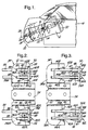
- An energy absorbing steering column 10 is disposed in a passenger compartment 12 of a body 14 of a motor vehicle.
- the steering column 10 includes a tubular mast jacket assembly 16 consisting of a lower mast 18 and an upper mast jacket 20 telescopically overlapping the lower mast jacket.
- the lower mast jacket is connected to a vertical panel 22 of the body 14 at the front of the passenger compartment through a lower bracket 24.
- a steering shaft 26 is supported on the mast jacket assembly 16 for rotation about a longitudinal centerline 28 of the steering column and connected to a steering gear, not shown, of the motor vehicle in front of the vertical panel 22.
- a steering hand wheel 30 is attached to the steering shaft at the top of the steering column.
- the upper mast jacket 20 and the steering shaft 26 are collapsible in the direction of the longitudinal centerline 28 of the steering column through a collapse stroke "S", Figure 1, in response to an impact on the steering hand wheel represented by a schematic force vector "F".
- An energy absorber 32 of the steering column 10 includes a mounting bracket 34 having a U-shaped body 36 rigidly attached to the upper mast jacket 20 and a pair of planar flanges 38A,38B on opposite sides of the upper mast jacket.
- the planar flanges are interrupted by respective ones of a pair of slots 40A,40B, Figure 3, open through respective ones of a pair of lateral edges 42A,42B of the planar flanges facing the steering hand wheel.
- Each of the slots 40A,40B has a pair of converging side edges 44A,44B intersecting corresponding ones of the lateral edges 42A,42B.
- the energy absorber 32 further includes a pair of capsules 46A,46B made of die cast metal or molded plastic.
- Each of the capsules has a top side 48, a bottom side 50, a pair of longitudinal sides 52A,52B converging at about the angle of convergence between the side edges 44A,44B of the slots 40A,40B, and a pair of lateral sides 54A,54B.
- the longitudinal sides 52A,52B of the capsules are interrupted by respective ones of a pair of channels 56A,56B between the lateral sides 54A,54B.
- the channels 56A,56B cooperate with the side edges 44A,44B in guiding the capsules 46A,46B into and out of the slots 40A,40B in the mounting bracket while restricting relative movement therebetween perpendicular to the planar flanges.
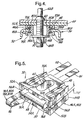
- a depth dimension "D", Figure 5 of the linear channels 56A,56B corresponds generally to the thickness of the planar flanges to minimize lash between the capsules and the mounting bracket perpendicular to the planar flanges.
- a plurality of molded-in-place plastic pins 58 retain the capsules in the slots 40A,40B.
- Each of the capsules 46A,46B is perforated between the top and the bottom sides 48,50 thereof by an elongated slot 60.
- a pair of generally vertical hanger bolts 62A,62B are rigidly attached to the body 14 of the motor vehicle perpendicular to a platform 64, Figure 4, on the body.
- the hanger bolts extend vertically through respective ones of the slots 60 in the capsules.
- a pair of fasteners 66A,66B on respective ones of the hanger bolts below the capsules cooperate with the hanger bolts in clamping the capsules against the platform 64.
- the capsules 46A,46B are thus rigidly attached to the body 14 of the motor vehicle and support the upper mast jacket 20 vertically for normal steering of the motor vehicle.
- each of the capsules 46A,46B has a convex anvil 68 on the lateral side 54A thereof perpendicular to the direction of the collapse stroke of the upper mast jacket 20.
- the top side 48 of each of the capsules in interrupted by a pair of upper guide slots 70A,70B on opposite sides of the elongated slot 60 parallel to the direction of the collapse stroke of the upper mast jacket.
- the upper guide slots 70A,70B intersect the lateral side 54A of the capsule tangent to the convex anvil 68 through respective ones of a pair of windows 72A,72B in the lateral side.
- each of the capsules is interrupted by a pair of lower guide slots 74A,74B, Figure 4, on opposite sides of the elongated slot 60 parallel to the direction of the collapse stroke of the upper mast jacket.
- the lower guide slots 74A,74B intersect the lateral side 54A of the capsule tangent to the convex anvil 68 through corresponding ones of a second pair of windows 76A,76B in the lateral side.
- the energy absorber 32 further includes two pairs of J-shaped flat metal straps 78A,78B and 80A,80B.
- Each of the flat metal straps 78A,78B and 80A,80B has a short side 82, a long side 84, and a concave web 86 between the short and the long sides.
- the flat metal straps 78A,78B are mounted on the capsule 46A with their webs 86 seated against the convex anvil 68, their short sides 82 seated in the upper guide slots 70A,70B through the windows 72A,72B and overlapping the closed end of the slot 40A in the mounting bracket, and their long sides 84 seated in the lower guide slots 74A,74B through the windows 76A,76B.
- Each of the flat metal straps 80A,80B is similarly seated on the capsule 46B.
- the short legs 82 of the metal straps 78A,78B and 80A,80B are attached by a plurality of welds 88 to the planar flanges 38A,38B of the mounting bracket.
- the impact on the steering hand wheel 30 represented by the schematic force vector "F" is transferred to the upper mast jacket 20 and is resisted by the plastic pins 58 until the material strength of the pins is exceeded.
- the collapse stroke "S" of the upper mast jacket commences and effects linear separation between the slots 40A,40B in the planar flanges of the mounting bracket and the capsules 46A,46B rigidly clamped to the vehicle body by the hanger bolts 62A,62B and the fasteners 66A,66B.
- the short sides 82 of the J-shaped flat metal straps 78A,78B and 80A,80B are tensioned between the welds 88 and the webs 86.
- the J-shaped flat metal straps are then pulled across the anvils and plastically deformed to convert into work a fraction of the kinetic energy of the impact "F" on the steering hand wheel.
- the windows 72A,72B guide the short sides 82 of the flat metal straps during energy absorbing plastic deformation.
- the windows 76A,76B maintain the webs 86 of the flat metal straps against the anvils 68 by preventing the long sides 84 of the J-shaped flat metal straps from flexing outward as the metal straps traverse the anvils.
Landscapes
- Engineering & Computer Science (AREA)
- Mechanical Engineering (AREA)
- General Engineering & Computer Science (AREA)
- Health & Medical Sciences (AREA)
- General Health & Medical Sciences (AREA)
- Physical Education & Sports Medicine (AREA)
- Chemical & Material Sciences (AREA)
- Combustion & Propulsion (AREA)
- Transportation (AREA)
- Steering Controls (AREA)
- Road Paving Structures (AREA)
Applications Claiming Priority (2)
| Application Number | Priority Date | Filing Date | Title |
|---|---|---|---|
| US7223498A | 1998-05-04 | 1998-05-04 | |
| US72234 | 1998-05-04 |
Publications (2)
| Publication Number | Publication Date |
|---|---|
| EP0955225A2 true EP0955225A2 (fr) | 1999-11-10 |
| EP0955225A3 EP0955225A3 (fr) | 2001-10-04 |
Family
ID=22106373
Family Applications (1)
| Application Number | Title | Priority Date | Filing Date |
|---|---|---|---|
| EP99201384A Withdrawn EP0955225A3 (fr) | 1998-05-04 | 1999-05-04 | Colonne de direction à absorption d'énergie pour véhicule à moteur |
Country Status (2)
| Country | Link |
|---|---|
| US (1) | US6086486A (fr) |
| EP (1) | EP0955225A3 (fr) |
Cited By (3)
| Publication number | Priority date | Publication date | Assignee | Title |
|---|---|---|---|---|
| EP1854701A2 (fr) | 2003-05-14 | 2007-11-14 | Toyota Jidosha Kabushiki Kaisha | Appareil de direction amortisseur |
| CN103313905A (zh) * | 2011-12-02 | 2013-09-18 | 日本精工株式会社 | 转向装置 |
| CN104602985A (zh) * | 2012-09-05 | 2015-05-06 | 萱场工业株式会社 | 转向装置 |
Families Citing this family (24)
| Publication number | Priority date | Publication date | Assignee | Title |
|---|---|---|---|---|
| US6328663B1 (en) * | 1999-08-13 | 2001-12-11 | Elliot A. Lipstock | Adjustable golf ball tee |
| US20030153395A1 (en) * | 2002-02-14 | 2003-08-14 | Lobeck David P. | Golf practice device |
| US20050181893A1 (en) * | 2003-08-20 | 2005-08-18 | Slaven James D. | One piece adjustable golf ball tee |
| CA2537815A1 (fr) * | 2003-09-05 | 2005-03-17 | E T Lim | Te de golf |
| GB2408944A (en) * | 2003-12-12 | 2005-06-15 | Thomas James Joseph Parker | Pivoting golf tee |
| US7086972B2 (en) * | 2004-03-26 | 2006-08-08 | Bainbridge Robert G | Height adjustable golf tee support apparatus |
| US7052416B2 (en) * | 2004-08-10 | 2006-05-30 | Rea Tower Chang | Golf range tee |
| US20060058120A1 (en) * | 2004-09-10 | 2006-03-16 | Terrence Anton | Articulated tee |
| SE0402837D0 (sv) * | 2004-11-19 | 2004-11-19 | Morgan Dandelius | Golf tee |
| US20070066422A1 (en) * | 2005-09-22 | 2007-03-22 | Michael Cirone | Force relieving golf tee |
| US7717811B1 (en) | 2006-10-25 | 2010-05-18 | Michael Joseph Merullo | Adjustable golf tee with associated measuring device |
| US20090325726A1 (en) * | 2008-06-27 | 2009-12-31 | Humphrey Robert J | Adjustable height practice golf tee |
| US7780553B2 (en) * | 2008-11-25 | 2010-08-24 | Palmer Andrew D | Golf practice apparatus |
| USD705877S1 (en) | 2009-06-28 | 2014-05-27 | Robert J. Humphrey | Two-part golf tee |
| USD705878S1 (en) | 2009-06-28 | 2014-05-27 | Robert J. Humphrey | Three-part golf tee |
| USD623248S1 (en) | 2009-07-17 | 2010-09-07 | Mike Radtke | Adjustable golf tee |
| EP2702153B1 (fr) | 2011-04-28 | 2018-12-12 | Novozymes, Inc. | Polypeptides à activité endoglucanase et polynucléotides codant pour les polypeptides |
| USD713899S1 (en) * | 2011-07-04 | 2014-09-23 | Kenneth Asbert | Combined golf tee and holder therefor |
| WO2015064345A1 (fr) * | 2013-10-31 | 2015-05-07 | 日本精工株式会社 | Dispositif de direction |
| US9737773B2 (en) | 2015-12-16 | 2017-08-22 | Creative Golf Innovations LLC | Adjustable golf tee |
| KR102007531B1 (ko) * | 2017-08-08 | 2019-08-06 | 이동기 | 골프 연습장용 매트의 홀 보호대 |
| USD971353S1 (en) * | 2020-11-19 | 2022-11-29 | David D. Kellogg | Adjustable golf tee assembly |
| US11701560B2 (en) | 2021-03-08 | 2023-07-18 | Practice Perfect Gold Solutions, LLC | Height-adjustable golf tee system |
| US20220362641A1 (en) | 2021-05-13 | 2022-11-17 | Anthony Joseph Baratta | Golf tee for a swing practice training mat |
Family Cites Families (12)
| Publication number | Priority date | Publication date | Assignee | Title |
|---|---|---|---|---|
| US1803907A (en) * | 1929-10-22 | 1931-05-05 | Maurice M Kruse | Adjustable golf tee and anchor therefor |
| US2457670A (en) * | 1946-04-19 | 1948-12-28 | Leaman S Harvey | Golf ball tee |
| DE1913054A1 (de) * | 1966-09-28 | 1970-02-19 | Gen Motors Corp | Sicherheitslenksaeule fuer Kraftfahrzeuge |
| US3516664A (en) * | 1967-04-26 | 1970-06-23 | Monsanto Co | Golf tee holder |
| GB1584984A (en) * | 1977-05-18 | 1981-02-18 | Accles & Pollock Ltd | Energy-absorbing steering columns |
| US4630716A (en) * | 1985-06-03 | 1986-12-23 | General Motors Corporation | Strip roll forming energy absorbing device |
| JPH0728048Y2 (ja) * | 1989-06-19 | 1995-06-28 | 日本精工株式会社 | 衝撃吸収式ステアリングコラム装置 |
| US5156403A (en) * | 1992-03-09 | 1992-10-20 | Martino Louis D | Golf tee for driving range |
| FR2714649B1 (fr) * | 1994-01-06 | 1996-03-15 | Nacam | Organe d'absorption d'énergie notamment pour colonne de direction de véhicule automobile. |
| US5706704A (en) * | 1996-03-25 | 1998-01-13 | General Motors Corporation | Energy absorbing steering column for motor vehicle |
| US5743819A (en) * | 1996-10-31 | 1998-04-28 | Chun; Won Ho | Golf tee setter |
| US5766100A (en) * | 1997-08-28 | 1998-06-16 | Dilmore; Clayton D. | Golf tee apparatus |
-
1999
- 1999-01-21 US US09/235,072 patent/US6086486A/en not_active Expired - Fee Related
- 1999-05-04 EP EP99201384A patent/EP0955225A3/fr not_active Withdrawn
Non-Patent Citations (1)
| Title |
|---|
| None |
Cited By (6)
| Publication number | Priority date | Publication date | Assignee | Title |
|---|---|---|---|---|
| EP1854701A2 (fr) | 2003-05-14 | 2007-11-14 | Toyota Jidosha Kabushiki Kaisha | Appareil de direction amortisseur |
| EP1854701A3 (fr) * | 2003-05-14 | 2007-11-28 | Toyota Jidosha Kabushiki Kaisha | Appareil de direction amortisseur |
| US7455320B2 (en) | 2003-05-14 | 2008-11-25 | Toyota Jidosha Kabushiki Kaisha | Shock absorbing steering apparatus |
| CN103313905A (zh) * | 2011-12-02 | 2013-09-18 | 日本精工株式会社 | 转向装置 |
| CN103313905B (zh) * | 2011-12-02 | 2016-01-13 | 日本精工株式会社 | 转向装置 |
| CN104602985A (zh) * | 2012-09-05 | 2015-05-06 | 萱场工业株式会社 | 转向装置 |
Also Published As
| Publication number | Publication date |
|---|---|
| US6086486A (en) | 2000-07-11 |
| EP0955225A3 (fr) | 2001-10-04 |
Similar Documents
| Publication | Publication Date | Title |
|---|---|---|
| EP0955225A2 (fr) | Colonne de direction à absorption d'énergie pour véhicule à moteur | |
| EP0769445B1 (fr) | Colonne de direction à absorption d'énergie pour véhicule à moteur | |
| US5706704A (en) | Energy absorbing steering column for motor vehicle | |
| EP1438224B1 (fr) | Ensemble direction de vehicule | |
| US5720496A (en) | Energy absorber for motor vehicle steering column | |
| CN109789889B (zh) | 转向柱组件以及在转向柱组件内吸收能量的方法 | |
| US6450532B1 (en) | Energy absorber for motor vehicle steering column | |
| US5468053A (en) | Energy absorbing beam construction for use with vehicle seat belt restraining systems | |
| EP1553004A2 (fr) | Direction absorbant les chocs | |
| EP3789238B1 (fr) | Structure de montage d'absorption d'énergie | |
| US6523893B2 (en) | Vehicle seat frame | |
| US5378021A (en) | Collapsible steering column apparatus | |
| US6669284B2 (en) | Device for guiding a seat of a vehicle | |
| US5209135A (en) | Impact absorbing type steering column device | |
| EP4082827B1 (fr) | Système de rail de siège pour un véhicule et véhicule comprenant un système de rail de siège | |
| US11052848B2 (en) | Energy absorbing device | |
| EP0415555B1 (fr) | Ensemble de colonne de direction télescopable | |
| CN216580686U (zh) | 一种带溃缩功能的转向管柱 | |
| CN114074624B (zh) | 车辆碰撞缓冲吸能系统及其制造方法 | |
| WO2006068567A1 (fr) | Moyens de fixation de siege a limitation de force | |
| JP2005088879A (ja) | エネルギー吸収ブラケット | |
| EP2049382B1 (fr) | Dispositif de connexion pour colonne de direction et traverse | |
| US20040234332A1 (en) | Safety device for removing a bolt, especially a pedal bolt, in a motor vehicle | |
| JP3645924B2 (ja) | 衝撃吸収構造体 | |
| US20220055692A1 (en) | Multilayer uniform deceleration unit |
Legal Events
| Date | Code | Title | Description |
|---|---|---|---|
| PUAI | Public reference made under article 153(3) epc to a published international application that has entered the european phase |
Free format text: ORIGINAL CODE: 0009012 |
|
| AK | Designated contracting states |
Kind code of ref document: A2 Designated state(s): AT BE CH CY DE DK ES FI FR GB GR IE IT LI LU MC NL PT SE Kind code of ref document: A2 Designated state(s): DE FR GB |
|
| AX | Request for extension of the european patent |
Free format text: AL;LT;LV;MK;RO;SI |
|
| PUAL | Search report despatched |
Free format text: ORIGINAL CODE: 0009013 |
|
| AK | Designated contracting states |
Kind code of ref document: A3 Designated state(s): AT BE CH CY DE DK ES FI FR GB GR IE IT LI LU MC NL PT SE |
|
| AX | Request for extension of the european patent |
Free format text: AL;LT;LV;MK;RO;SI |
|
| 17P | Request for examination filed |
Effective date: 20020404 |
|
| AKX | Designation fees paid |
Free format text: DE FR GB |
|
| 17Q | First examination report despatched |
Effective date: 20030603 |
|
| STAA | Information on the status of an ep patent application or granted ep patent |
Free format text: STATUS: THE APPLICATION IS DEEMED TO BE WITHDRAWN |
|
| 18D | Application deemed to be withdrawn |
Effective date: 20031014 |