EP0955255A1 - Dispositif extracteur à vis sans fin, pourvu de moyens d'entraînement en rotation améliorée - Google Patents
Dispositif extracteur à vis sans fin, pourvu de moyens d'entraînement en rotation améliorée Download PDFInfo
- Publication number
- EP0955255A1 EP0955255A1 EP99401103A EP99401103A EP0955255A1 EP 0955255 A1 EP0955255 A1 EP 0955255A1 EP 99401103 A EP99401103 A EP 99401103A EP 99401103 A EP99401103 A EP 99401103A EP 0955255 A1 EP0955255 A1 EP 0955255A1
- Authority
- EP
- European Patent Office
- Prior art keywords
- casing
- branch
- frame
- screw
- silo
- Prior art date
- Legal status (The legal status is an assumption and is not a legal conclusion. Google has not performed a legal analysis and makes no representation as to the accuracy of the status listed.)
- Granted
Links
- 239000000463 material Substances 0.000 claims abstract description 14
- 230000007246 mechanism Effects 0.000 claims description 4
- 239000008187 granular material Substances 0.000 claims description 2
- 239000007787 solid Substances 0.000 claims description 2
- 230000001681 protective effect Effects 0.000 description 4
- 238000000605 extraction Methods 0.000 description 3
- 239000003638 chemical reducing agent Substances 0.000 description 2
- 239000002184 metal Substances 0.000 description 2
- 239000011343 solid material Substances 0.000 description 2
- 238000013016 damping Methods 0.000 description 1
- 238000009434 installation Methods 0.000 description 1
- 238000012423 maintenance Methods 0.000 description 1
- 238000000034 method Methods 0.000 description 1
- 238000013021 overheating Methods 0.000 description 1
Images


Classifications
-
- B—PERFORMING OPERATIONS; TRANSPORTING
- B65—CONVEYING; PACKING; STORING; HANDLING THIN OR FILAMENTARY MATERIAL
- B65G—TRANSPORT OR STORAGE DEVICES, e.g. CONVEYORS FOR LOADING OR TIPPING, SHOP CONVEYOR SYSTEMS OR PNEUMATIC TUBE CONVEYORS
- B65G65/00—Loading or unloading
- B65G65/30—Methods or devices for filling or emptying bunkers, hoppers, tanks, or like containers, of interest apart from their use in particular chemical or physical processes or their application in particular machines, e.g. not covered by a single other subclass
- B65G65/34—Emptying devices
- B65G65/40—Devices for emptying otherwise than from the top
- B65G65/46—Devices for emptying otherwise than from the top using screw conveyors
- B65G65/466—Devices for emptying otherwise than from the top using screw conveyors arranged to be movable
Definitions
- the present invention relates to a device for extracting solid materials (pulverulent or in grains) stored on an area (or in a silo), of the type comprising at least one worm screw intended to evacuate the material towards a central evacuation orifice.
- a frame in the general shape of an inverted U of 90 °, and between the branches of which is disposed a casing associated with first means for driving the screw in rotation about its axis, and on which the screw is fixed, the casing and the screw being driven in rotation about a vertical axis by second drive means, so that the screw scans the area (or the bottom of the silo).
- the frictional forces can be such as to cause the casing to block.
- the screws are then no longer rotated about the vertical axis of the silo, but rotate only on themselves, which causes the material to be discharged towards the orifice, only in line with each screw.
- this empty prism compared to the rest of the silo filled with material, creates differential stresses in the silo, which tend to ovalize it. These constraints are harmful and dangerous.
- the difficulty is all the greater since the operator is not often able to detect such a blockage of the casing, because the material continues to be evacuated, at least for a time, according to the process explained above. .
- the present invention aims to remedy this drawback and proposes, according to a first aspect, a device which makes it possible to ensure the drive of the casing in all situations, by reducing friction as much as possible.
- the means for driving the housing in rotation are relatively bulky and fragile, being made up of different mechanisms cooperating with each other. Also due to the deformation of the frame, the drive of the casing may no longer be optimally ensured.
- the invention aims to propose means for driving the casing in rotation about its own axis, which are reliable and avoid blockages.
- the casing is held in its upper part, relative to the upper branch of the U, by guide means, allowing a slight differential movement of the casing relative to said branch, in a substantially axial vertical direction.
- the casing protrudes relative to the plane formed by the upper branch of the inverted U through which passes an opening whose edges are provided with said guides.
- the second drive means comprise a motor and a drive mechanism associated with the crown.
- the crown is serrated and cooperates with a gear itself associated with said motor.
- a silo referenced 1 having a cylindrical wall 2.
- the extractor assembly referenced 3 In the center of the silo is located the extractor assembly referenced 3 according to the invention, and comprising a frame 4 surmounted by a protective cone 5.
- Two collinear endless screws, referenced 6 and 7, are arranged substantially along a diameter of the silo, and near and parallel to the bottom of the silo.
- the two screws 6 and 7 are rotated, on the one hand around their own axis, in opposite directions to one another, and on the other hand around the vertical central axis of the silo , according to a rotational movement explained below.
- An evacuation orifice (not shown, as being located just below the frame 4 and the protective cone 5) is provided in the center of the silo.
- the solid materials or materials capable of being stored in the silo and conveyed by the extractor assembly of the invention, to the discharge orifice are of the pulverulent or granular type, or all types of similar materials, capable of '' be stored in a silo, or in an outdoor area, and capable of being transported and moved by worm.
- the collinear screws 6 and 7 are arranged along a straight line slightly offset from the central axis of the silo. As a result, during their rotational movement substantially around the central axis of the silo, the screws leave a "dead" area which is not swept by the screws. This zone is occupied by a radial element 9, in relief with respect to the bottom 8 of the silo, of length equivalent to the space available between the distal end 4a of the frame 4 and the cylindrical wall 2 of the silo, the width of the element in relief being substantially equivalent to the width of the frame in the circumferential direction, at the end face 4a of said frame.
- the relief element 9 is made for example of concrete or welded metal panels, and preferably has an inclined upper face or has two inclined faces, to avoid stagnation of the material on said relief element 9.
- FIG. 2 shows a side view of the extractor assembly according to the invention, seen along the axis II-II of FIG. 1.
- This figure shows the frame 4, the protective cone 5, the screws 6 and 7 (shown partially).
- the protective cone 5 is extended downwards by a skirt 10.
- a skirt 10 On the bottom of the silo 8 is provided an opening 11 opening into a discharge hopper or hood 12, connected to discharge pipes to the outside (known in themselves and not shown), in order to convey the material extracted from the silo to means of transport or treatment.
- Figure 3 a schematic sectional view along a vertical plane, of the frame.
- a casing 13 rotatably mounted inside the two horizontal branches of the U, and driven in rotation by first drive means described later in detail, and including the block 14 motor with gear motor.
- second drive means On the housing 13 are fixed the screws 6 and 7 (perpendicular to Figure 3).
- the screws are rotated about their axis by means of second drive means, described later in detail, and in particular including a motor 15, a reduction unit 16 and a pulley 17 connected to the common shaft 18 of the two screws 6 and 7 collinear.
- the frame 4 is preferably formed from welded metal panels.
- the casing 13 has a cross section, in vertical section, generally rectangular, elongated in the vertical direction with the exception of a bulged part 19 along one of the vertical sides.
- This bulged part 19 houses the shaft 18 common to the collinear screws 6 and 7 (not shown), and is associated with the cooperating pulley 17, for example by means of a chain 20, with a pulley 21 provided in the block geared motor 16.
- the latter is fixed to the lateral inner wall 22 (opposite the bulge 19), by means of a fixing means 23 known in itself.
- the motor 15 drives the pulley 21, inside the geared motor unit 16, by means of a shaft 24 and of a damping drive joint 25 known in itself.
- the casing 13 rests by its lower face, that is to say its base, on the lower branch 26 of the inverted U forming the frame 4, by means of a crown 27.
- the crown 27 is serrated on its inner periphery and is centered on the axis X-X.
- the crown 27 is associated with bearings 27A with balls or needles which transmit the forces, resulting in particular from the weight of the casing, on the upper face 26A of the lower branch 26 of the U-shaped frame 4.
- second drive means consisting of a reducer motor unit 14, including the motor 28 and the motor reducer unit 29, capable of transmitting, via a pinion 30, engaged on the crown 27, the rotational movement of the motor 28 (of horizontal axis) to the crown 27.
- the crown 27 and the associated ball or needle bearings 27A have the advantage of allowing the housing to be supported on the frame 4, and more particularly on the upper face 26A of the lower branch 26, under optimal conditions of solidity while allowing the rotational movement of the casing 13 around the axis XX, relative to the fixed frame 4.
- the drive in rotation of the casing is facilitated by the second drive means including a pinion 30 and the gear motor 29.
- the second drive means are thus simple in design and maintenance. In addition, they carry out a direct drive of the casing, which avoids vibrations and other harmful phenomena.
- the casing 13 is connected to the frame 4 at its upper part, as described in detail below, with reference to FIGS. 5 and 6.
- the casing 13 is linked to the frame 4 in its upper part, by means allowing a relative movement, of small amplitude, between the casing and the upper branch 31 of the inverted U formed by the frame 4.
- the upper face 32 (FIG. 5) of the casing has a cylindrical shoulder 33 extended by a cylindrical part 34 (centered on the axis XX), itself partially closed in its upper part by a crown 35, leaving a passage 36 free central open, for the drive shaft 24 of the motor 15.
- the motor 15 is fixed and linked to the frame (by means not shown), while the casing 13 is rotated as explained above.
- the relative movement between the rotating casing 13 and the stationary motor 15 is made possible by connecting means 37 (FIG. 6) and allowing the motor 15 to rest on the casing, while allowing said relative movement of the casing / motor.
- the casing 13 is linked to the lower face 38 of the upper branch 31 of the inverted U forming the frame 4, by means of guide means bearing the general reference 39 (FIG. 6).
- the guide means allow an axial movement (axis XX) between the casing, and more precisely the extended cylindrical part 34 of the latter, and the lower face 38 of the upper branch 31 of said U.
- the guide means 39 consist for example of a crown 40, fixed by known means on the horizontal underside 38 of the frame.
- the guide ring 40 has a substantially vertical cylindrical surface against which is likely to slide, with low friction, the cylindrical extension 34 forming a body with the casing 13.
- the travel is generally a few mm, resulting from the deformations to which the frame 4 and in particular the upper branch 31, which tends to collapse downwards.
Landscapes
- Engineering & Computer Science (AREA)
- Mechanical Engineering (AREA)
- Filling Or Emptying Of Bunkers, Hoppers, And Tanks (AREA)
- Valve Device For Special Equipments (AREA)
- Refuse Collection And Transfer (AREA)
- Extrusion Moulding Of Plastics Or The Like (AREA)
- Screw Conveyors (AREA)
- Extraction Or Liquid Replacement (AREA)
- Centrifugal Separators (AREA)
Abstract
Description
- La présente invention concerne un dispositif extracteur de matières solides (pulvérulentes ou en grains) stockées sur une aire (ou dans un silo), du type comprenant au moins une vis sans fin destinée à évacuer la matière vers un orifice d'évacuation central au-dessus duquel est disposé un bâti, en forme générale de U renversé de 90°, et entre les branches duquel est disposé un carter associé à des premiers moyens d'entraînement de la vis en rotation autour de son axe, et sur lequel la vis est fixée, le carter et la vis étant entraînés en rotation autour d'un axe vertical par des seconds moyens d'entraînement, de façon que la vis balaye l'aire (ou le fond du silo).
- La famille des dispositifs d'extraction à laquelle appartient la présente invention est décrite dans la demande de brevet numéro 76 05688.
- Ce type d'extracteur connu donne satisfaction, mais il est susceptible d'être amélioré.
- En effet, la grande quantité de matières stockées crée sur le bâti en forme de U, des forces et contraintes très élevées, qui tendent à déformer le bâti, notamment en déformant vers le bas la branche supérieure horizontale du U renversé.
- Or, le carter selon l'art antérieur, décrit dans le brevet ci-dessus, est fixé sur les branches du U par l'intermédiaire de pivots associés à des paliers.
- La déformation du bâti mentionnée précédemment entraîne, on le comprend, des efforts très importants sur les pivots et le palier, qui créent des forces de frottement élevées. Ces dernières obligent à augmenter la puissance des moteurs, et en outre créent des risques d'échauffement et de bris, ce qui fragilise le mécanisme d'entraînement.
- Les forces de frottement peuvent être telles qu'elles provoquent le blocage du carter. Les vis ne sont alors plus entraînées en rotation autour de l'axe vertical du silo, mais tournent uniquement sur elles-mêmes, ce qui entraîne l'évacuation de la matière vers l'orifice, uniquement au droit de chaque vis. Il se forme ainsi un prisme triangulaire centré sur la vis, dans le tas de matière stockée. Dans le cas d'un silo, ce prisme vide, par rapport au reste du silo rempli de matière, crée des contraintes différentielles dans le silo, qui tendent à ovaliser celui-ci. Ces contraintes sont néfastes et dangereuses. La difficulté est d'autant plus grande que l'opérateur n'est pas souvent en mesure de détecter un tel blocage du carter, du fait que la matière continue à être évacuée, au moins pendant un temps, selon le processus expliqué ci-dessus.
- La présente invention vise à remédier à cet inconvénient et propose, selon un premier aspect, un dispositif qui permette d'assurer l'entraînement du carter dans toutes les situations, en réduisant les frottements au maximum.
- Par ailleurs, les moyens d'entraînement en rotation du carter, selon l'art antérieur défini par le brevet ci-dessus, sont relativement encombrants et fragiles, étant constitués de différents mécanismes coopérant les uns avec les autres. Egalement du fait de la déformation du bâti, l'entraînement du carter risque de ne plus être assuré de manière optimale.
- Dans ce contexte, selon son second aspect, l'invention vise à proposer des moyens d'entraînement du carter en rotation autour de son propre axe, qui soient fiables et évitent les blocages.
- A cette fin, selon l'invention, l'ensemble extracteur pour matières solides, pulvérulentes ou en grains, stockées sur une aire ou dans un silo, du type comprenant au moins une vis sans fin destinée à évacuer la matière vers un orifice d'évacuation central au-dessus duquel est disposé un bâti en forme générale de U renversé à 90° et entre les branches horizontales duquel est disposé un carter associé à des moyens d'entraînement de la vis en rotation autour de son axe, et sur lequel la vis est fixée, le carter et la vis étant entraînés en rotation autour d'un axe vertical par des seconds moyens d'entraînement, est caractérisé en ce que ledit carter repose par sa base sur la branche horizontale inférieure du U renversé, par l'intermédiaire d'une couronne reliée à ladite branche par des moyens autorisant le mouvement de rotation de l'ensemble plateau/carter.
- Avantageusement, le carter est maintenu en sa partie supérieure, par rapport à la branche supérieure du U, par des moyens de guidage, autorisant un léger débattement différentiel du carter par rapport à ladite branche, selon une direction sensiblement axiale verticale.
- De préférence, le carter dépasse par rapport au plan formé par la branche supérieure du U renversé que traverse une ouverture dont les bords sont pourvus desdits guides.
- Dans une forme préférée, les seconds moyens d'entraînement comportent un moteur et un mécanisme d'entraînement associés à la couronne.
- De préférence, la couronne est dentelée et coopère avec un engrenage lui-même associé audit moteur.
- L'invention sera bien comprise à la lumière de la description qui suit se rapportant à un exemple illustratif et non limitatif, en référence aux dessins annexés dans lesquels :
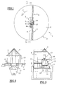
- La figure 1 est une vue de dessus schématique de l'ensemble d'extraction disposé dans un silo;
- La figure 2 est une vue de côté partielle selon l'axe II-II de la figure 1;
- La figure 3 est une vue en coupe schématique du bâti selon un plan vertical;
- La figure 4 est une vue à plus grande échelle et plus détaillée de la figure 3;
- La figure 5 est une vue agrandie en coupe verticale du carter et des premiers et seconds moyens d'entraînement; et
- La figure 6 est une vue à échelle agrandie des moyens de guidage du carter en partie supérieure.
- L'invention sera décrite ci-après en référence à un ensemble extracteur disposé dans un silo, étant entendu que l'invention peut être également appliquée à une aire de stockage, disposée à l'air libre.
- En référence à la figure 1, on a représenté en coupe selon un plan horizontal, un silo référencé 1, comportant une paroi cylindrique 2. Au centre du silo est disposé l'ensemble extracteur référencé 3 selon l'invention, et comportant un bâti 4 surmonté d'un cône de protection 5. Deux vis sans fin colinéaires, référencées 6 et 7, sont disposées sensiblement selon un diamètre du silo, et à proximité et parallèlement au fond du silo.
- Les deux vis 6 et 7 sont animées d'un mouvement de rotation, d'une part autour de leur propre axe, en sens inverse l'une de l'autre, et d'autre part autour de l'axe central vertical du silo, selon un mouvement de rotation explicité ci-après.
- Un orifice d'évacuation (non représenté, car étant situé juste en dessous du bâti 4 et du cône de protection 5) est prévu au centre du silo.
- Les mouvements conjugués de rotation des vis, d'une part sur elles-mêmes, et d'autre part autour de l'axe vertical du silo, entraînent l'acheminement de la matière stockée dans le silo, vers l'orifice d'évacuation.
- Les matières ou matériaux solides susceptibles d'être stockés dans le silo et acheminés par l'ensemble extracteur de l'invention, vers l'orifice d'évacuation, sont du type pulvérulentes ou en grains, ou tous types de matériaux similaires, susceptibles d'être stockés en silo, ou sur une aire à l'extérieur, et susceptibles d'être acheminés et déplacés par vis sans fin.
- Les vis 6 et 7 colinéaires sont disposées selon une droite décalée légèrement par rapport à l'axe central du silo. Il en résulte que pendant leur mouvement de rotation sensiblement autour de l'axe central du silo, les vis laissent une zone « morte » qui n'est pas balayée par les vis. Cette zone est occupée par un élément radial 9, en relief par rapport au fond 8 du silo, de longueur équivalent à l'espace disponible entre l'extrémité distale 4a du bâti 4 et la paroi 2 cylindrique du silo, la largeur de l'élément en relief étant sensiblement équivalente à la largeur du bâti dans le sens circonférentiel, au niveau de la face 4a d'extrémité dudit bâti.
- L'élément en relief 9 est réalisé par exemple en béton ou en panneaux métalliques soudés, et présente de préférence, une face supérieure inclinée ou présente deux faces inclinées, pour éviter la stagnation de la matière sur ledit élément en relief 9.
- D'autres éléments techniques de fonctionnement et d'installation (connus en eux-mêmes) sont prévus, non représentés et non décrits, et l'homme de l'art pourra trouver dans le brevet numéro 76 05688 des informations concernant ces éléments connus.
- On a représenté sur la figure 2 une vue de côté de l'ensemble extracteur selon l'invention, vu selon l'axe II-II de la figure 1.
- On retrouve sur cette figure le bâti 4, le cône de protection 5, les vis 6 et 7 (montrées partiellement).
- Le cône de protection 5 est prolongé vers le bas par une jupe 10. Sur le fond du silo 8 est prévue une ouverture 11 débouchant dans une trémie ou hotte 12 d'évacuation, reliée à des conduits d'évacuation vers l'extérieur (connus en eux-mêmes et non représentés), afin d'acheminer la matière extraite du silo vers des moyens de transport ou de traitement.
- On a représenté sur la figure 3 une vue en coupe schématique selon un plan vertical, du bâti.
- Celui-ci présente la forme générale d'un U, renversé à 90°. Pour les besoins de la compréhension, les parois extérieures délimitant le U formant le bâti 4 sont représentées en traits gras.
- A l'intérieur du bâti en U renversé, est disposé un carter 13 monté à rotation à l'intérieur des deux branches horizontales du U, et entraîné en rotation par des premiers moyens d'entraînement décrits ultérieurement en détail, et incluant le bloc 14 moteur à motoréducteur.
- Sur le carter 13 sont fixées les vis 6 et 7 (perpendiculaires à la figure 3). Les vis sont entraînées en rotation autour de leur axe par l'intermédiaire de seconds moyens d'entraînement, décrits ultérieurement en détail, et incluant notamment un moteur 15, un bloc réducteur 16 et une poulie 17 reliée à l'arbre commun 18 des deux vis 6 et 7 colinéaires.
- Le bâti 4 est formé de préférence de panneaux métalliques soudés.
- En référence à la figure 4, on a représenté à une échelle agrandie et avec plus de détails, l'ensemble extracteur montré sur la figure 3. On retrouve les éléments communs aux deux figures qui portent les mêmes références.
- Le carter 13 présente une section droite, en coupe verticale, générale rectangulaire, allongée dans le sens vertical à l'exception d'une partie renflée 19 selon l'un des côtés verticaux. Cette partie renflée 19 abrite l'arbre 18 commun aux vis colinéaires 6 et 7 (non représentées), et est associée à la poulie 17 coopérant, par l'intermédiaire par exemple d'une chaîne 20, avec une poulie 21 prévue dans le bloc motoréducteur 16. Ce dernier est fixé sur la paroi intérieure latérale 22(opposée au renflement 19), par l'intermédiaire d'un moyen de fixation 23 connu en lui-même.
- Le moteur 15 entraîne la poulie 21, à l'intérieur du bloc motoréducteur 16, par l'intermédiaire d'un arbre 24 et d'un joint d'entraînement amortisseur 25 connu en lui-même.
- Il est fait référence, à ce stade, aux figures 4 et 5.
- Le carter 13 repose par sa face inférieure, c'est-à-dire sa base, sur la branche inférieure 26 du U renversé formant le bâti 4, par l'intermédiaire d'une couronne 27.
- La couronne 27 est dentelée sur sa périphérie intérieure et est centrée sur l'axe X-X.
- La couronne 27 est associée à des roulements 27A à billes ou à aiguilles qui permettent de transmettre les efforts, résultant notamment du poids du carter, sur la face supérieure 26A de la branche inférieure 26 du bâti 4 en U.
- Le carter 13 doit être entraîné en rotation, pour permettre l'entraînement en rotation des vis autour de l'axe X-X. A cette fin, il est prévu des seconds moyens d'entraînement constitués d'un bloc moteur à réducteur 14, incluant le moteur 28 et le bloc motoréducteur 29, aptes à transmettre, par l'intermédiaire d'un pignon 30, engréné sur la couronne 27, le mouvement de rotation du moteur 28 (d'axe horizontal) à la couronne 27.
- La couronne 27 et les roulements à billes ou à aiguilles 27A associés présentent l'avantage de permettre le support du carter sur le bâti 4, et plus particulièrement sur la face supérieure 26A de la branche inférieure 26, dans des conditions optimales de solidité tout en permettant le mouvement de rotation du carter 13 autour de l'axe X-X, par rapport au bâti 4 fixe.
- De plus, l'entraînement en rotation du carter est facilité par les seconds moyens d'entraînement incluant un pignon 30 et le motoréducteur 29. Les seconds moyens d'entraînement sont ainsi simples de conception et d'entretien. De plus, ils réalisent un entraînement direct du carter, ce qui évite les vibrations et autres phénomènes néfastes.
- Le carter 13 est relié au bâti 4 en sa partie supérieure, de la manière décrite en détail ci-après, en référence aux figures 5 et 6.
- A cette fin, le carter 13 est lié au bâti 4 en sa partie supérieure, par des moyens permettant un débattement relatif, de faible amplitude, entre le carter et la branche supérieure 31 du U renversé formé par le bâti 4.
- Plus particulièrement, la face supérieure 32 (figure 5) du carter, présente un épaulement cylindrique 33 prolongé par une partie cylindrique 34 (centrée sur l'axe X-X), elle-même obturée partiellement en sa partie supérieure par une couronne 35, laissant un passage 36 libre ouvert central, pour l'arbre d'entraînement 24 du moteur 15.
- Le moteur 15 est fixe et lié au bâti (par des moyens non représentés), alors que le carter 13 est entraîné en rotation comme explicité ci-dessus.
- Le mouvement relatif entre le carter 13 tournant et le moteur fixe 15 est rendu possible par des moyens de liaison 37 (figure 6) et permettant au moteur 15 de reposer sur le carter, tout en autorisant ledit mouvement relatif carter/moteur.
- Le carter 13 est lié à la face inférieure 38 de la branche supérieure 31 du U renversé formant le bâti 4, par l'intermédiaire de moyens de guidage portant la référence générale 39 (figure 6).
- Les moyens de guidage autorisent un débattement axial (axe X-X) entre le carter, et plus précisément la partie prolongée cylindrique 34 de celui-ci, et la face inférieure 38 de la branche supérieure 31 dudit U.
- Les moyens de guidage 39 sont constitués par exemple d'une couronne 40, fixée par des moyens connus sur la face inférieure horizontale 38 du bâti. La couronne de guidage 40 présente une surface cylindrique sensiblement verticale contre laquelle est susceptible de glisser, avec un faible frottement, le prolongement 34 cylindrique faisant corps avec le carter 13. Le débattement est en général de quelques mm, résultant des déformations auxquelles est soumis le bâti 4 et notamment la branche supérieure 31, qui tend à s'affaisser vers le bas.
Claims (5)
- Ensemble extracteur pour matières solides, pulvérulentes ou en grains, stockées sur une aire ou dans un silo, du type comprenant au moins une vis sans fin, destinée à évacuer la matière vers un orifice d'évacuation central au-dessus duquel est disposé un bâti en forme générale de U renversé à 90° et entre les branches horizontales duquel est disposé un carter associé à des moyens d'entraînement de la vis en rotation autour de son axe, et sur lequel la vis est fixée, le carter et la vis étant entraînés en rotation autour d'un axe vertical par des seconds moyens d'entraînement, caractérisé en ce que ledit carter repose par sa base sur la branche horizontale inférieure du U renversé, par l'intermédiaire d'une couronne reliée à ladite branche par des moyens autorisant le mouvement de rotation de l'ensemble plateau/carter.
- Ensemble selon la revendication 1, caractérisé en ce que le carter est maintenu en sa partie supérieure, par rapport à la branche supérieure du U, par des moyens de guidage, autorisant un léger débattement différentiel du carter par rapport à ladite branche, selon une direction sensiblement axiale verticale.
- Ensemble selon la revendication 2, caractérisé en ce que le carter dépasse par rapport au plan formé par la branche supérieure du U renversé que traverse une ouverture dont les bords sont pourvus desdits guides.
- Ensemble selon l'une des revendications 1 à 3, caractérisé en ce que les seconds moyens d'entraînement comportent un moteur et un mécanisme d'entraînement associés à la couronne.
- Ensemble selon la revendication 4, caractérisé en ce que la couronne est dentelée et coopère avec un engrenage lui-même associé audit moteur.
Applications Claiming Priority (2)
| Application Number | Priority Date | Filing Date | Title |
|---|---|---|---|
| FR9805787A FR2778395B1 (fr) | 1998-05-07 | 1998-05-07 | Dispositif extracteur a vis sans fin, pourvu de moyens d'entrainement en rotation amelioree |
| FR9805787 | 1998-05-07 |
Publications (2)
| Publication Number | Publication Date |
|---|---|
| EP0955255A1 true EP0955255A1 (fr) | 1999-11-10 |
| EP0955255B1 EP0955255B1 (fr) | 2002-12-11 |
Family
ID=9526128
Family Applications (1)
| Application Number | Title | Priority Date | Filing Date |
|---|---|---|---|
| EP99401103A Expired - Lifetime EP0955255B1 (fr) | 1998-05-07 | 1999-05-05 | Dispositif extracteur à vis sans fin, pourvu de moyens d'entraínement en rotation améliorée |
Country Status (4)
| Country | Link |
|---|---|
| EP (1) | EP0955255B1 (fr) |
| AT (1) | ATE229468T1 (fr) |
| DE (1) | DE69904389D1 (fr) |
| FR (1) | FR2778395B1 (fr) |
Cited By (2)
| Publication number | Priority date | Publication date | Assignee | Title |
|---|---|---|---|---|
| GB2518896A (en) * | 2013-10-07 | 2015-04-08 | Guttridge Ltd | A sweep auger |
| US11008186B2 (en) | 2010-02-19 | 2021-05-18 | Sudenga Industries, Inc. | Bin sweep collector ring assembly |
Citations (2)
| Publication number | Priority date | Publication date | Assignee | Title |
|---|---|---|---|---|
| FR2341506A1 (fr) * | 1976-02-23 | 1977-09-16 | Cantenot Paul | Dispositif pour extraction de materiaux solides |
| FR2626262A1 (fr) * | 1988-01-25 | 1989-07-28 | Starvrac | Extracteur pour silo de stockage |
-
1998
- 1998-05-07 FR FR9805787A patent/FR2778395B1/fr not_active Expired - Fee Related
-
1999
- 1999-05-05 DE DE69904389T patent/DE69904389D1/de not_active Expired - Lifetime
- 1999-05-05 AT AT99401103T patent/ATE229468T1/de not_active IP Right Cessation
- 1999-05-05 EP EP99401103A patent/EP0955255B1/fr not_active Expired - Lifetime
Patent Citations (2)
| Publication number | Priority date | Publication date | Assignee | Title |
|---|---|---|---|---|
| FR2341506A1 (fr) * | 1976-02-23 | 1977-09-16 | Cantenot Paul | Dispositif pour extraction de materiaux solides |
| FR2626262A1 (fr) * | 1988-01-25 | 1989-07-28 | Starvrac | Extracteur pour silo de stockage |
Cited By (2)
| Publication number | Priority date | Publication date | Assignee | Title |
|---|---|---|---|---|
| US11008186B2 (en) | 2010-02-19 | 2021-05-18 | Sudenga Industries, Inc. | Bin sweep collector ring assembly |
| GB2518896A (en) * | 2013-10-07 | 2015-04-08 | Guttridge Ltd | A sweep auger |
Also Published As
| Publication number | Publication date |
|---|---|
| EP0955255B1 (fr) | 2002-12-11 |
| FR2778395A1 (fr) | 1999-11-12 |
| DE69904389D1 (de) | 2003-01-23 |
| ATE229468T1 (de) | 2002-12-15 |
| FR2778395B1 (fr) | 2000-06-16 |
Similar Documents
| Publication | Publication Date | Title |
|---|---|---|
| EP0143057B1 (fr) | Dispositif d'extraction notamment pour silos à base circulaire | |
| EP0060782B1 (fr) | Perfectionnement aux dispositifs d'extraction de matières solides en vrac à l'état finement divisé depuis le fond d'un silo | |
| EP0513529B1 (fr) | Installation de chargement d'un four à cuve | |
| EP0955255B1 (fr) | Dispositif extracteur à vis sans fin, pourvu de moyens d'entraínement en rotation améliorée | |
| WO1998023528A1 (fr) | Bloc de translation a ecrou debrayable pour ensembles de levage a vis | |
| EP1516836B1 (fr) | Dispositif de vidange d'un silo à fond sensiblement plat | |
| FR2463085A1 (fr) | Perfectionnements aux extracteurs a au moins une vis d'archimede a axe horizontal tournant autour d'un axe vertical au fond d'un silo | |
| FR2664508A1 (fr) | Centrifugeuse a fonctionnement continu. | |
| FR2686076A1 (fr) | Dispositif pour l'evacuation de matieres granuleuses ou pulverulentes depuis un silo circulaire de stockage. | |
| BE898210A (fr) | Extrémité de tubulure pour tubulure d'aspiration d'un élévateur pneumatique. | |
| FR2626262A1 (fr) | Extracteur pour silo de stockage | |
| EP0955256B1 (fr) | Ensemble extracteur de matières solides à vis sans fin pourvu de moyens d'accès améliorés | |
| FR2767634A1 (fr) | Godet desileur | |
| FR2778396A1 (fr) | Perfectionnements aux extracteurs a vis sur silos | |
| FR2563821A2 (fr) | Extracteur de produits denses pour cellules cylindriques de stockage | |
| EP3647041B1 (fr) | Dispositif de compactage de déchets | |
| FR2664346A1 (fr) | Carter d'engrenages, en particulier pour engrenages a roues a denture droite/vis sans fin ou engrenages a vis sans fin. | |
| FR2890284A1 (fr) | Ensileuse pour silo-boudin | |
| FR2686075A1 (fr) | Dispositif pour l'evacuation de matieres granuleuses, pulverulentes en vrac depuis un silo circulaire de stockage. | |
| EP1806305A1 (fr) | Dispositif de nettoyage de la paroi de fond d'un silo | |
| FR2686328A1 (fr) | Dispositif d'extraction de matieres pulverulentes ou granuleuses, notamment depuis un silo circulaire. | |
| EP0410916B1 (fr) | Dispositif d'extraction longitudinale pour trémies en longueur ou en file, en particulier pour trémies de cokeries | |
| EP0150632B1 (fr) | Dispositif pour l'évacuation de produits pulvérulents contenus dans un silo | |
| FR2595332A1 (fr) | Silo, muni de moyens de decharge, en particulier adapte aux materiaux occasionnant un pont | |
| FR2778585A1 (fr) | Montage de rotor pour broyeur a axe vertical |
Legal Events
| Date | Code | Title | Description |
|---|---|---|---|
| PUAI | Public reference made under article 153(3) epc to a published international application that has entered the european phase |
Free format text: ORIGINAL CODE: 0009012 |
|
| AK | Designated contracting states |
Kind code of ref document: A1 Designated state(s): AT BE DE DK ES FI FR GB GR IE IT MC NL PT SE |
|
| AX | Request for extension of the european patent |
Free format text: AL;LT;LV;MK;RO;SI |
|
| 17P | Request for examination filed |
Effective date: 20000509 |
|
| AKX | Designation fees paid |
Free format text: AT BE DE DK ES FI FR GB GR IE IT MC NL PT SE |
|
| 17Q | First examination report despatched |
Effective date: 20010214 |
|
| GRAG | Despatch of communication of intention to grant |
Free format text: ORIGINAL CODE: EPIDOS AGRA |
|
| GRAG | Despatch of communication of intention to grant |
Free format text: ORIGINAL CODE: EPIDOS AGRA |
|
| GRAH | Despatch of communication of intention to grant a patent |
Free format text: ORIGINAL CODE: EPIDOS IGRA |
|
| GRAH | Despatch of communication of intention to grant a patent |
Free format text: ORIGINAL CODE: EPIDOS IGRA |
|
| GRAA | (expected) grant |
Free format text: ORIGINAL CODE: 0009210 |
|
| AK | Designated contracting states |
Kind code of ref document: B1 Designated state(s): AT BE DE DK ES FI FR GB GR IE IT MC NL PT SE |
|
| PG25 | Lapsed in a contracting state [announced via postgrant information from national office to epo] |
Ref country code: NL Free format text: LAPSE BECAUSE OF FAILURE TO SUBMIT A TRANSLATION OF THE DESCRIPTION OR TO PAY THE FEE WITHIN THE PRESCRIBED TIME-LIMIT Effective date: 20021211 Ref country code: IT Free format text: LAPSE BECAUSE OF FAILURE TO SUBMIT A TRANSLATION OF THE DESCRIPTION OR TO PAY THE FEE WITHIN THE PRESCRIBED TIME-LIMIT;WARNING: LAPSES OF ITALIAN PATENTS WITH EFFECTIVE DATE BEFORE 2007 MAY HAVE OCCURRED AT ANY TIME BEFORE 2007. THE CORRECT EFFECTIVE DATE MAY BE DIFFERENT FROM THE ONE RECORDED. Effective date: 20021211 Ref country code: IE Free format text: LAPSE BECAUSE OF FAILURE TO SUBMIT A TRANSLATION OF THE DESCRIPTION OR TO PAY THE FEE WITHIN THE PRESCRIBED TIME-LIMIT Effective date: 20021211 Ref country code: GR Free format text: LAPSE BECAUSE OF FAILURE TO SUBMIT A TRANSLATION OF THE DESCRIPTION OR TO PAY THE FEE WITHIN THE PRESCRIBED TIME-LIMIT Effective date: 20021211 Ref country code: GB Free format text: LAPSE BECAUSE OF FAILURE TO SUBMIT A TRANSLATION OF THE DESCRIPTION OR TO PAY THE FEE WITHIN THE PRESCRIBED TIME-LIMIT Effective date: 20021211 Ref country code: FI Free format text: LAPSE BECAUSE OF FAILURE TO SUBMIT A TRANSLATION OF THE DESCRIPTION OR TO PAY THE FEE WITHIN THE PRESCRIBED TIME-LIMIT Effective date: 20021211 Ref country code: AT Free format text: LAPSE BECAUSE OF FAILURE TO SUBMIT A TRANSLATION OF THE DESCRIPTION OR TO PAY THE FEE WITHIN THE PRESCRIBED TIME-LIMIT Effective date: 20021211 |
|
| REF | Corresponds to: |
Ref document number: 229468 Country of ref document: AT Date of ref document: 20021215 Kind code of ref document: T |
|
| REG | Reference to a national code |
Ref country code: GB Ref legal event code: FG4D Free format text: NOT ENGLISH |
|
| REG | Reference to a national code |
Ref country code: IE Ref legal event code: FG4D Free format text: FRENCH |
|
| REF | Corresponds to: |
Ref document number: 69904389 Country of ref document: DE Date of ref document: 20030123 |
|
| PG25 | Lapsed in a contracting state [announced via postgrant information from national office to epo] |
Ref country code: SE Free format text: LAPSE BECAUSE OF FAILURE TO SUBMIT A TRANSLATION OF THE DESCRIPTION OR TO PAY THE FEE WITHIN THE PRESCRIBED TIME-LIMIT Effective date: 20030311 Ref country code: PT Free format text: LAPSE BECAUSE OF FAILURE TO SUBMIT A TRANSLATION OF THE DESCRIPTION OR TO PAY THE FEE WITHIN THE PRESCRIBED TIME-LIMIT Effective date: 20030311 Ref country code: DK Free format text: LAPSE BECAUSE OF FAILURE TO SUBMIT A TRANSLATION OF THE DESCRIPTION OR TO PAY THE FEE WITHIN THE PRESCRIBED TIME-LIMIT Effective date: 20030311 |
|
| PG25 | Lapsed in a contracting state [announced via postgrant information from national office to epo] |
Ref country code: DE Free format text: LAPSE BECAUSE OF FAILURE TO SUBMIT A TRANSLATION OF THE DESCRIPTION OR TO PAY THE FEE WITHIN THE PRESCRIBED TIME-LIMIT Effective date: 20030312 |
|
| NLV1 | Nl: lapsed or annulled due to failure to fulfill the requirements of art. 29p and 29m of the patents act | ||
| PG25 | Lapsed in a contracting state [announced via postgrant information from national office to epo] |
Ref country code: MC Free format text: LAPSE BECAUSE OF NON-PAYMENT OF DUE FEES Effective date: 20030531 Ref country code: BE Free format text: LAPSE BECAUSE OF NON-PAYMENT OF DUE FEES Effective date: 20030531 |
|
| GBV | Gb: ep patent (uk) treated as always having been void in accordance with gb section 77(7)/1977 [no translation filed] |
Effective date: 20021211 |
|
| PG25 | Lapsed in a contracting state [announced via postgrant information from national office to epo] |
Ref country code: ES Free format text: LAPSE BECAUSE OF FAILURE TO SUBMIT A TRANSLATION OF THE DESCRIPTION OR TO PAY THE FEE WITHIN THE PRESCRIBED TIME-LIMIT Effective date: 20030627 |
|
| REG | Reference to a national code |
Ref country code: IE Ref legal event code: FD4D Ref document number: 0955255E Country of ref document: IE |
|
| PLBE | No opposition filed within time limit |
Free format text: ORIGINAL CODE: 0009261 |
|
| STAA | Information on the status of an ep patent application or granted ep patent |
Free format text: STATUS: NO OPPOSITION FILED WITHIN TIME LIMIT |
|
| BERE | Be: lapsed |
Owner name: S.A. *STARVRAC Effective date: 20030531 |
|
| 26N | No opposition filed |
Effective date: 20030912 |
|
| PGFP | Annual fee paid to national office [announced via postgrant information from national office to epo] |
Ref country code: FR Payment date: 20070530 Year of fee payment: 9 |
|
| REG | Reference to a national code |
Ref country code: FR Ref legal event code: ST Effective date: 20090119 |
|
| PG25 | Lapsed in a contracting state [announced via postgrant information from national office to epo] |
Ref country code: FR Free format text: LAPSE BECAUSE OF NON-PAYMENT OF DUE FEES Effective date: 20080602 |