EP0955256A1 - Schneckenaustragsvorrichtung für schüttgut mit verbesserten zugangsmitteln - Google Patents
Schneckenaustragsvorrichtung für schüttgut mit verbesserten zugangsmitteln Download PDFInfo
- Publication number
- EP0955256A1 EP0955256A1 EP99401104A EP99401104A EP0955256A1 EP 0955256 A1 EP0955256 A1 EP 0955256A1 EP 99401104 A EP99401104 A EP 99401104A EP 99401104 A EP99401104 A EP 99401104A EP 0955256 A1 EP0955256 A1 EP 0955256A1
- Authority
- EP
- European Patent Office
- Prior art keywords
- frame
- silo
- assembly according
- casing
- screws
- Prior art date
- Legal status (The legal status is an assumption and is not a legal conclusion. Google has not performed a legal analysis and makes no representation as to the accuracy of the status listed.)
- Granted
Links
- 239000013590 bulk material Substances 0.000 title 1
- 238000007599 discharging Methods 0.000 title 1
- 239000000463 material Substances 0.000 claims abstract description 8
- 238000006073 displacement reaction Methods 0.000 claims description 7
- 239000011343 solid material Substances 0.000 claims description 4
- 238000012423 maintenance Methods 0.000 abstract description 6
- 230000008439 repair process Effects 0.000 description 6
- 230000007246 mechanism Effects 0.000 description 5
- 230000000712 assembly Effects 0.000 description 4
- 238000000429 assembly Methods 0.000 description 4
- 230000001681 protective effect Effects 0.000 description 3
- 238000001816 cooling Methods 0.000 description 2
- 239000002184 metal Substances 0.000 description 2
- 238000005273 aeration Methods 0.000 description 1
- 239000000470 constituent Substances 0.000 description 1
- 238000010276 construction Methods 0.000 description 1
- 239000000428 dust Substances 0.000 description 1
- 238000000605 extraction Methods 0.000 description 1
- 230000005484 gravity Effects 0.000 description 1
- 238000011065 in-situ storage Methods 0.000 description 1
- 238000009434 installation Methods 0.000 description 1
- 238000000034 method Methods 0.000 description 1
- 239000007787 solid Substances 0.000 description 1
- 238000003860 storage Methods 0.000 description 1
- 238000009423 ventilation Methods 0.000 description 1
Images


Classifications
-
- B—PERFORMING OPERATIONS; TRANSPORTING
- B65—CONVEYING; PACKING; STORING; HANDLING THIN OR FILAMENTARY MATERIAL
- B65G—TRANSPORT OR STORAGE DEVICES, e.g. CONVEYORS FOR LOADING OR TIPPING, SHOP CONVEYOR SYSTEMS OR PNEUMATIC TUBE CONVEYORS
- B65G65/00—Loading or unloading
- B65G65/30—Methods or devices for filling or emptying bunkers, hoppers, tanks, or like containers, of interest apart from their use in particular chemical or physical processes or their application in particular machines, e.g. not covered by a single other subclass
- B65G65/34—Emptying devices
- B65G65/40—Devices for emptying otherwise than from the top
- B65G65/46—Devices for emptying otherwise than from the top using screw conveyors
- B65G65/466—Devices for emptying otherwise than from the top using screw conveyors arranged to be movable
Definitions
- the present invention relates to an extractor assembly for powdery or granular solids (stored in an area or in a silo).
- Such assemblies include two collinear endless screws, arranged substantially along a diameter and intended to evacuate the material towards a central evacuation orifice, provided on the area (or at the bottom of the silo) and above which a frame is fixed.
- a central evacuation orifice provided on the area (or at the bottom of the silo) and above which a frame is fixed.
- the present invention applies more particularly to devices belonging to the family described by French patent 76 05688.
- Extractor assemblies of known type are generally satisfactory, but they nevertheless have drawbacks and are therefore capable of improvement.
- the object of the present invention is to remedy these drawbacks by proposing an extractor assembly which has means allowing easy and safe access to the drive means, the worms and the mechanisms arranged in the frame.
- the underside of the lower branch of the U has a first opening, on the side of the vertical part of the inverted U.
- the underside of the lower leg has a second opening.
- the assembly further comprises means for handling and moving all or part of the first and second drive means, respectively.
- the handling and displacement means comprise at least one rail, a carriage and a system of hoists.
- the lower face of the upper branch has an opening, allowing access to the space delimited by the two horizontal U branches.
- the casing advantageously comprises a side access hatch.
- the distal end of the upper branch of the U is extended along a vertical plane, by a skirt partially closing off the space delimited by the two horizontal branches of said U.
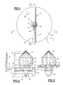
- a silo referenced 1 having a cylindrical wall 2.
- the extractor assembly referenced 3 At the center of the silo is located the extractor assembly referenced 3 according to the invention, and comprising a frame 4 surmounted by a protective cone 5.
- Two collinear endless screws referenced 6 and 7, are arranged substantially along a diameter of the silo, and near and parallel to the bottom of the silo.
- the two screws are rotated, on the one hand around their own axis, in opposite direction, and on the other hand around the vertical central axis of the silo, according to a rotational movement explained below .
- An evacuation orifice (not shown as being located just below the frame 4 and the protective cone 5) is provided in the center of the silo.
- the solid materials or materials capable of being stored in the silo and conveyed by the extractor assembly of the invention, to the discharge orifice are of the pulverulent or granular type, or all types of similar materials, capable of '' be stored in a silo, or in an outdoor area, and capable of being transported and moved by worm.
- the collinear screws 6 and 7 are arranged along a straight line slightly offset from the central axis of the silo. It follows that during their rotational movement around the central axis of the silo substantially, the screws leave a "dead" area which is not swept by the screws. This zone is occupied by a radial element 9, in relief with respect to the bottom 8 of the silo, of length equivalent to the space available between the end 4a of the frame and the cylindrical wall 2 of the silo, the width of the element in relief being substantially equivalent to the width of the frame in the circumferential direction, at the end face 4a of said frame.
- the relief element 9 is made for example of concrete or welded metal panels, and preferably has, for reasons of simplification of construction, a prismatic section whose upper face is inclined or has two inclined faces to avoid stagnation of the material on said element in relief 9.
- FIG 2 there is shown a partial sectional side view of the extractor assembly of the invention seen according to segment II-II of Figure 1, the screws having rotated 90 degrees in the direction of arrow f relative to the representation of Figure 1.
- a casing 11 Inside the frame 4 is disposed a casing 11 on which the screws 6 and 7 are fixed (which are not visible in the figure because being perpendicular to the plane thereof), only the axis 12 common to the two screws is represented.
- the evacuation orifice provided on the bottom 8 of the silo bears the reference 13 and at the base of the frame 4 is provided an evacuation hood 14 opening into an evacuation and access chamber B provided vertically of the opening 13.
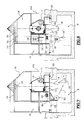
- FIG. 4 showing a sectional view along a vertical plane, on an enlarged scale, of the extractor assembly (corresponding substantially to the view in FIG. 2).
- the frame 4 has a general shape of U inverted at 90 °. For reasons of convenience and to improve understanding of the drawing, the outer wall of the frame has been shown in bold lines.
- the frame 4 is hollow and made of assembled or welded metal panels.
- the U forming the frame 4 thus comprises two horizontal branches, namely a lower branch 15 and an upper branch 16.
- the skirt 10 (FIGS. 2 and 3) is advantageously extended (FIG. 4) downwards by a vertical extension 10A, at the level of the upper branch 16, so as to partially close off the space between said branches 15 and 16.
- the casing 11 In the space delimited by and located between the two branches 15 and 16, is disposed the casing 11 able to be driven in rotation about the vertical axis XX, by drive means, comprising a motor 18 and a geared motor unit 19, arranged substantially inside the hollow lower branch 15, and near the upper face 20 of the latter.
- the geared motor unit 19 is connected by means of gears and pinions, with a crown fixed on the base of the casing, the crown being serrated on its inner periphery.
- the crown rests on the upper face 20 of the lower branch 15 of the frame 4, by means of needle or ball bearings.
- the casing 11 is held in its upper part by guide means allowing its rotation relative to the frame 4, around the axis X-X.
- a motor 21 Inside the casing 11 are provided means for driving the screws (in rotation about their own axis) by means of a motor 21, fixed relative to the frame 4.
- the motor 21 is more particularly arranged at inside the upper branch 16 of the frame 4.
- the motor shaft transmits the rotational movement to the screws around their own axis, by means of a geared motor 22 and a pulley 23 fixed to the shaft 12 common to both screws.
- the gearmotor 22 and the pulley 23 are disposed inside the casing 11 and fixed to the latter by means 24 known in themselves.
- connection between the fixed motor 21 and the rotating casing 11 is not described further and is the subject of a patent application filed on the same day in the name of the applicant.
- Air circulation means 25 are also provided, for dust evacuation and cooling, and arranged near and under the lower face 26 of the lower branch 15 of the U-shaped frame. These means are the subject of a request. patent filed the same day, in the name of the applicant.
- the frame 4 rests, by means of known fixing means, on studs 27 and 28, projecting relative to the vertical inner wall of the chamber B for evacuation and access.
- Repair or maintenance operations are likely to be carried out by one or more parties who access the frame 4 through the chamber B, which is itself connected to a passage leading to the outside of the silo (not shown).
- the extractor assembly of the invention has the following features which facilitate access to the parts to be repaired or maintained, and their disassembly and routing in the frame 4 and their evacuation.
- the lower face 26 of the lower branch 15 has a first distal opening 29 provided on the side from the base of the inverted U, that is to say on the side opposite the distal ends of the branches 15 and 16 of said U.
- a second proximal opening 30 is provided on said lower face 26, offset towards the axis X-X relative to the first distal opening 29.
- the operator is then able, after having passed through the distal opening 29, to access the interior of the space 31, then by a ladder 32 fixed to a vertical internal wall 33 of the frame, access inside the hollow upper branch 16. It can then carry out the necessary operations, for example on the motor 21.
- Figures 5 to 8 are the equivalent of Figure 4 on a smaller scale, in terms of the structure of the frame 4 and the means and mechanisms that it contains.
- FIG. 5 the displacement and the routing of the motor 21 are shown, intended for driving the screws in rotation about their own axis.
- the horizontal upper face 34 of the upper branch 16 of the frame 4 has inside the frame, a horizontal rail 35, the ends of which abut against the end walls, respectively 36 of the upper branch 16 and 4a of the frame 4 .
- the rail 35 is associated with a carriage 37 movable on said rail by means of wheels or rollers, in a known manner, said carriage being associated with hooks and a system of hoists allowing, using chains or the like, the lifting , after disassembly, of the motor 21 in the vertical upward direction.
- the position shown in FIG. 5 is obtained in solid lines, for the motor 21, the carriage 37 and the hoist system 38.
- FIG. 6 shows a later phase intended for the routing and the displacement of the geared motor unit 22 arranged inside the casing 11.
- the original position of the gearmotor 22 is shown in solid lines. After disassembly thereof, it being understood that the motor 21 has been disassembled and removed, the procedure is similar in that the hooking means are arranged on the gearmotor 22, associated with the hoist 38.
- the hoists are started to go up towards the upper wall 34 of the frame 4, the gearmotor 22.
- the carriage 37 is then moved in translation (arrow "g" and position 22 'of the gearmotor ). Once the carriage 37 has reached the end of its travel, that is to say in the vertical space 31, the carriage 37 is immobilized; the hoists are then set in motion to lower the geared motor unit 22 "into said space 31, and to pass the latter through the distal opening 29.
- the geared motor 22 is then routed, via chamber B, to the outside of the silo.
- access to the interior of the casing 11 can be achieved by the following means.
- An opening 40 is provided on the lower face 41 of the upper branch 16 of the frame 4, and opening onto the interior space delimited by the two lower 15 and upper 16 branches respectively.
- the operator enters the vertical space 31, then into the interior space of the hollow upper branch 16, passes through the opening 40 to access the space defined between the two said branches 15 and 16, to access finally to the casing.
- the casing 11 comprises a front hatch 42 in its substantially axial vertical part, and in particular the bulged part 43 containing the pulley 23 and the axis 12 common to the two screws.
- the operator is able, following the path described above and represented by the arrows "i” and “j", to penetrate inside the casing to carry out the necessary operations of disassembly, maintenance or repair or other.
- the arrow “k” symbolizes the exit of the speaker.
- the hatch 42 consists of a panel articulated on the corresponding face of the casing 11.
- FIG. 7 shows the disassembly and the routing of the air circulation means 25 after their disassembly, directly from inside the chamber B and moved (arrow “l”) towards the outside of the silo, the means being shown dotted in a disassembled position 25 'and in transit.
- the means 25 for ventilation and aeration are arranged in line with the proximal opening 30 provided on the lower face 26, and therefore make it possible to evacuate by this same opening the second drive means (motor 18 and geared motor 19), after dismantling and routing, as described below with reference to Figure 8.
- hooking means are used by means of the hoists 38, associated with the carriage 37, to lift the motor and gearmotor assembly, to position 18 ' / 19 'shown in Figure 8 in dotted lines. Then, the rail 37 is left fixed, then one acts on the hoist so as to lower the motor and geared motor assembly 18/19 through the opening 30, to thus access the evacuation chamber B, in a position 18 "/ 19" also shown in dotted lines, for evacuation to the outside or repair in situ.
- extension 10A (FIGS. 4 to 8) of the skirt 10 downwards makes it possible to protect the space situated between the branches 15 and 16, from the stored material and facilitates, or even makes possible, the interventions described above. , in particular to access the casing 11 via the hatch 42.
Landscapes
- Engineering & Computer Science (AREA)
- Mechanical Engineering (AREA)
- Filling Or Emptying Of Bunkers, Hoppers, And Tanks (AREA)
- Screw Conveyors (AREA)
- Disintegrating Or Milling (AREA)
- Refuse Collection And Transfer (AREA)
Applications Claiming Priority (2)
| Application Number | Priority Date | Filing Date | Title |
|---|---|---|---|
| FR9805786A FR2778392B1 (fr) | 1998-05-07 | 1998-05-07 | Ensemble extracteur de matieres solides a vis sans fin pourvu de moyens d'acces ameliores |
| FR9805786 | 1998-05-07 |
Publications (2)
| Publication Number | Publication Date |
|---|---|
| EP0955256A1 true EP0955256A1 (de) | 1999-11-10 |
| EP0955256B1 EP0955256B1 (de) | 2002-08-14 |
Family
ID=9526127
Family Applications (1)
| Application Number | Title | Priority Date | Filing Date |
|---|---|---|---|
| EP99401104A Expired - Lifetime EP0955256B1 (de) | 1998-05-07 | 1999-05-05 | Schneckenaustragsvorrichtung für Schüttgut mit verbesserten Zugangsmitteln |
Country Status (4)
| Country | Link |
|---|---|
| EP (1) | EP0955256B1 (de) |
| AT (1) | ATE222208T1 (de) |
| DE (1) | DE69902499D1 (de) |
| FR (1) | FR2778392B1 (de) |
Citations (2)
| Publication number | Priority date | Publication date | Assignee | Title |
|---|---|---|---|---|
| FR2669012A1 (fr) * | 1990-11-13 | 1992-05-15 | Defi Holding | Systeme d'extraction des matieres granuleuses ou pulverulentes contenues dans un silo. |
| FR2686328A1 (fr) * | 1992-01-17 | 1993-07-23 | Starvrac Sa | Dispositif d'extraction de matieres pulverulentes ou granuleuses, notamment depuis un silo circulaire. |
-
1998
- 1998-05-07 FR FR9805786A patent/FR2778392B1/fr not_active Expired - Fee Related
-
1999
- 1999-05-05 AT AT99401104T patent/ATE222208T1/de not_active IP Right Cessation
- 1999-05-05 DE DE69902499T patent/DE69902499D1/de not_active Expired - Lifetime
- 1999-05-05 EP EP99401104A patent/EP0955256B1/de not_active Expired - Lifetime
Patent Citations (2)
| Publication number | Priority date | Publication date | Assignee | Title |
|---|---|---|---|---|
| FR2669012A1 (fr) * | 1990-11-13 | 1992-05-15 | Defi Holding | Systeme d'extraction des matieres granuleuses ou pulverulentes contenues dans un silo. |
| FR2686328A1 (fr) * | 1992-01-17 | 1993-07-23 | Starvrac Sa | Dispositif d'extraction de matieres pulverulentes ou granuleuses, notamment depuis un silo circulaire. |
Also Published As
| Publication number | Publication date |
|---|---|
| FR2778392A1 (fr) | 1999-11-12 |
| ATE222208T1 (de) | 2002-08-15 |
| FR2778392B1 (fr) | 2000-06-16 |
| DE69902499D1 (de) | 2002-09-19 |
| EP0955256B1 (de) | 2002-08-14 |
Similar Documents
| Publication | Publication Date | Title |
|---|---|---|
| CA2510673C (fr) | Avion multimoteur a puits de descente | |
| FR2634544A1 (fr) | Dispositif de manutention d'une goulotte de distribution d'un four a cuve et mecanisme d'entrainement adapte a ce dispositif | |
| FR2638825A1 (fr) | Installation de chargement d'un four a cuve | |
| EP1427655A1 (de) | Übergabevorrichtung für einen linearförderer | |
| EP1019312A1 (de) | Linearschlitten mit entkuppelbarer mutter für hebevorrichtungen mit spindelantrieb | |
| EP0955256B1 (de) | Schneckenaustragsvorrichtung für Schüttgut mit verbesserten Zugangsmitteln | |
| FR2511660A1 (fr) | Chargeur a translation adaptable sur tous types de materiel roulant ou en poste d'attente existant ou a construire | |
| FR2461664A1 (fr) | Conteneur a dechets avec moyens de supportage et de manutention | |
| EP3755627A1 (de) | Antriebseinheit für ein flugzeug mit hebestellen und fahrgestelle zur unterstützung einer solchen einheit | |
| FR2911858A1 (fr) | Dispositif elevateur-basculeur pour conteneur,notamment de pieces en vrac | |
| EP0955255B1 (de) | Schneckenaustragsvorrichtung mit verbessertem Drehantrieb | |
| FR2769874A1 (fr) | Toit decouvrable pour receptacle de transport a chargement par le haut notamment pour benne ou semi-benne | |
| EP0838385B1 (de) | Transportfahrzeug mit seitlich montierter Planenabdeckung | |
| FR3029187A1 (fr) | Dispositif de chargement en dechets d'une benne de dechetterie depuis une plateforme | |
| FR2799894A1 (fr) | Borne de distribution retractable | |
| EP3138104B1 (de) | Vorrichtung zum öffnen und schliessen einer öffnung am boden eines beckens zum eindämmen von bestrahltem brennstoff | |
| FR2664508A1 (fr) | Centrifugeuse a fonctionnement continu. | |
| FR2778394A1 (fr) | Ensemble extracteur a vis pour matieres solides | |
| BE1024960B1 (fr) | Conteneur a fond mouvant pour le transport d'enrobes routiers | |
| FR2788755A1 (fr) | Nacelle d'ouverture des portes d'un camion en phase de dechargement | |
| EP0090981A2 (de) | Transport- und Speichereinrichtung für Schüttgüter | |
| EP0225268B1 (de) | Ladevorrichtung für Müllsammelbehälter auf Müllfahrzeugen | |
| FR2685277A1 (fr) | Vehicule de transport bache. | |
| FR2611670A2 (fr) | Dispositif de stockage et de distribution d'objets | |
| FR2492791A1 (fr) | Dispositif de manutention de materiaux en vrac, notamment pour le dechargement de navires |
Legal Events
| Date | Code | Title | Description |
|---|---|---|---|
| PUAI | Public reference made under article 153(3) epc to a published international application that has entered the european phase |
Free format text: ORIGINAL CODE: 0009012 |
|
| AK | Designated contracting states |
Kind code of ref document: A1 Designated state(s): AT BE DE DK ES FI FR GB GR IE IT MC NL PT SE |
|
| AX | Request for extension of the european patent |
Free format text: AL;LT;LV;MK;RO;SI |
|
| 17P | Request for examination filed |
Effective date: 20000509 |
|
| AKX | Designation fees paid |
Free format text: AT BE DE DK ES FI FR GB GR IE IT MC NL PT SE |
|
| 17Q | First examination report despatched |
Effective date: 20010209 |
|
| GRAG | Despatch of communication of intention to grant |
Free format text: ORIGINAL CODE: EPIDOS AGRA |
|
| GRAG | Despatch of communication of intention to grant |
Free format text: ORIGINAL CODE: EPIDOS AGRA |
|
| GRAH | Despatch of communication of intention to grant a patent |
Free format text: ORIGINAL CODE: EPIDOS IGRA |
|
| GRAH | Despatch of communication of intention to grant a patent |
Free format text: ORIGINAL CODE: EPIDOS IGRA |
|
| GRAA | (expected) grant |
Free format text: ORIGINAL CODE: 0009210 |
|
| AK | Designated contracting states |
Kind code of ref document: B1 Designated state(s): AT BE DE DK ES FI FR GB GR IE IT MC NL PT SE |
|
| PG25 | Lapsed in a contracting state [announced via postgrant information from national office to epo] |
Ref country code: NL Free format text: LAPSE BECAUSE OF FAILURE TO SUBMIT A TRANSLATION OF THE DESCRIPTION OR TO PAY THE FEE WITHIN THE PRESCRIBED TIME-LIMIT Effective date: 20020814 Ref country code: IT Free format text: LAPSE BECAUSE OF FAILURE TO SUBMIT A TRANSLATION OF THE DESCRIPTION OR TO PAY THE FEE WITHIN THE PRESCRIBED TIME-LIMIT;WARNING: LAPSES OF ITALIAN PATENTS WITH EFFECTIVE DATE BEFORE 2007 MAY HAVE OCCURRED AT ANY TIME BEFORE 2007. THE CORRECT EFFECTIVE DATE MAY BE DIFFERENT FROM THE ONE RECORDED. Effective date: 20020814 Ref country code: IE Free format text: LAPSE BECAUSE OF FAILURE TO SUBMIT A TRANSLATION OF THE DESCRIPTION OR TO PAY THE FEE WITHIN THE PRESCRIBED TIME-LIMIT Effective date: 20020814 Ref country code: GR Free format text: LAPSE BECAUSE OF FAILURE TO SUBMIT A TRANSLATION OF THE DESCRIPTION OR TO PAY THE FEE WITHIN THE PRESCRIBED TIME-LIMIT Effective date: 20020814 Ref country code: GB Free format text: LAPSE BECAUSE OF FAILURE TO SUBMIT A TRANSLATION OF THE DESCRIPTION OR TO PAY THE FEE WITHIN THE PRESCRIBED TIME-LIMIT Effective date: 20020814 Ref country code: FI Free format text: LAPSE BECAUSE OF FAILURE TO SUBMIT A TRANSLATION OF THE DESCRIPTION OR TO PAY THE FEE WITHIN THE PRESCRIBED TIME-LIMIT Effective date: 20020814 Ref country code: AT Free format text: LAPSE BECAUSE OF FAILURE TO SUBMIT A TRANSLATION OF THE DESCRIPTION OR TO PAY THE FEE WITHIN THE PRESCRIBED TIME-LIMIT Effective date: 20020814 |
|
| REF | Corresponds to: |
Ref document number: 222208 Country of ref document: AT Date of ref document: 20020815 Kind code of ref document: T |
|
| REG | Reference to a national code |
Ref country code: GB Ref legal event code: FG4D Free format text: NOT ENGLISH |
|
| REG | Reference to a national code |
Ref country code: IE Ref legal event code: FG4D Free format text: FRENCH |
|
| REF | Corresponds to: |
Ref document number: 69902499 Country of ref document: DE Date of ref document: 20020919 |
|
| PG25 | Lapsed in a contracting state [announced via postgrant information from national office to epo] |
Ref country code: SE Free format text: LAPSE BECAUSE OF FAILURE TO SUBMIT A TRANSLATION OF THE DESCRIPTION OR TO PAY THE FEE WITHIN THE PRESCRIBED TIME-LIMIT Effective date: 20021114 Ref country code: DK Free format text: LAPSE BECAUSE OF FAILURE TO SUBMIT A TRANSLATION OF THE DESCRIPTION OR TO PAY THE FEE WITHIN THE PRESCRIBED TIME-LIMIT Effective date: 20021114 |
|
| PG25 | Lapsed in a contracting state [announced via postgrant information from national office to epo] |
Ref country code: DE Free format text: LAPSE BECAUSE OF FAILURE TO SUBMIT A TRANSLATION OF THE DESCRIPTION OR TO PAY THE FEE WITHIN THE PRESCRIBED TIME-LIMIT Effective date: 20021115 |
|
| PG25 | Lapsed in a contracting state [announced via postgrant information from national office to epo] |
Ref country code: PT Free format text: LAPSE BECAUSE OF FAILURE TO SUBMIT A TRANSLATION OF THE DESCRIPTION OR TO PAY THE FEE WITHIN THE PRESCRIBED TIME-LIMIT Effective date: 20021129 |
|
| NLV1 | Nl: lapsed or annulled due to failure to fulfill the requirements of art. 29p and 29m of the patents act | ||
| GBV | Gb: ep patent (uk) treated as always having been void in accordance with gb section 77(7)/1977 [no translation filed] |
Effective date: 20020814 |
|
| PG25 | Lapsed in a contracting state [announced via postgrant information from national office to epo] |
Ref country code: ES Free format text: LAPSE BECAUSE OF FAILURE TO SUBMIT A TRANSLATION OF THE DESCRIPTION OR TO PAY THE FEE WITHIN THE PRESCRIBED TIME-LIMIT Effective date: 20030228 |
|
| PG25 | Lapsed in a contracting state [announced via postgrant information from national office to epo] |
Ref country code: MC Free format text: LAPSE BECAUSE OF NON-PAYMENT OF DUE FEES Effective date: 20030531 |
|
| PLBE | No opposition filed within time limit |
Free format text: ORIGINAL CODE: 0009261 |
|
| STAA | Information on the status of an ep patent application or granted ep patent |
Free format text: STATUS: NO OPPOSITION FILED WITHIN TIME LIMIT |
|
| REG | Reference to a national code |
Ref country code: IE Ref legal event code: FD4D Ref document number: 0955256E Country of ref document: IE |
|
| 26N | No opposition filed |
Effective date: 20030515 |
|
| PGFP | Annual fee paid to national office [announced via postgrant information from national office to epo] |
Ref country code: BE Payment date: 20070613 Year of fee payment: 9 |
|
| PGFP | Annual fee paid to national office [announced via postgrant information from national office to epo] |
Ref country code: FR Payment date: 20070530 Year of fee payment: 9 |
|
| BERE | Be: lapsed |
Owner name: S.A. *STARVRAC Effective date: 20080531 |
|
| REG | Reference to a national code |
Ref country code: FR Ref legal event code: ST Effective date: 20090119 |
|
| PG25 | Lapsed in a contracting state [announced via postgrant information from national office to epo] |
Ref country code: BE Free format text: LAPSE BECAUSE OF NON-PAYMENT OF DUE FEES Effective date: 20080531 |
|
| PG25 | Lapsed in a contracting state [announced via postgrant information from national office to epo] |
Ref country code: FR Free format text: LAPSE BECAUSE OF NON-PAYMENT OF DUE FEES Effective date: 20080602 |