EP0955429B1 - Ferrure pour porte, fenetre ou analogue - Google Patents
Ferrure pour porte, fenetre ou analogue Download PDFInfo
- Publication number
- EP0955429B1 EP0955429B1 EP19980440083 EP98440083A EP0955429B1 EP 0955429 B1 EP0955429 B1 EP 0955429B1 EP 19980440083 EP19980440083 EP 19980440083 EP 98440083 A EP98440083 A EP 98440083A EP 0955429 B1 EP0955429 B1 EP 0955429B1
- Authority
- EP
- European Patent Office
- Prior art keywords
- fitting
- screw
- hole
- door
- window
- Prior art date
- Legal status (The legal status is an assumption and is not a legal conclusion. Google has not performed a legal analysis and makes no representation as to the accuracy of the status listed.)
- Expired - Lifetime
Links
- 239000002184 metal Substances 0.000 claims abstract description 4
- 229910001220 stainless steel Inorganic materials 0.000 claims abstract description 3
- 239000010935 stainless steel Substances 0.000 claims abstract description 3
- 239000000463 material Substances 0.000 claims description 4
- 239000007769 metal material Substances 0.000 claims description 3
- 238000006073 displacement reaction Methods 0.000 claims description 2
- 230000037431 insertion Effects 0.000 claims 1
- 238000003780 insertion Methods 0.000 claims 1
- 210000000056 organ Anatomy 0.000 claims 1
- 238000010079 rubber tapping Methods 0.000 description 9
- 238000004519 manufacturing process Methods 0.000 description 8
- 241001080024 Telles Species 0.000 description 1
- 230000000977 initiatory effect Effects 0.000 description 1
- 238000000034 method Methods 0.000 description 1
- 238000000465 moulding Methods 0.000 description 1
- 229920002994 synthetic fiber Polymers 0.000 description 1
Images
Classifications
-
- F—MECHANICAL ENGINEERING; LIGHTING; HEATING; WEAPONS; BLASTING
- F16—ENGINEERING ELEMENTS AND UNITS; GENERAL MEASURES FOR PRODUCING AND MAINTAINING EFFECTIVE FUNCTIONING OF MACHINES OR INSTALLATIONS; THERMAL INSULATION IN GENERAL
- F16B—DEVICES FOR FASTENING OR SECURING CONSTRUCTIONAL ELEMENTS OR MACHINE PARTS TOGETHER, e.g. NAILS, BOLTS, CIRCLIPS, CLAMPS, CLIPS OR WEDGES; JOINTS OR JOINTING
- F16B37/00—Nuts or like thread-engaging members
- F16B37/005—Nuts or like thread-engaging members into which threads are cut during screwing
-
- E—FIXED CONSTRUCTIONS
- E05—LOCKS; KEYS; WINDOW OR DOOR FITTINGS; SAFES
- E05B—LOCKS; ACCESSORIES THEREFOR; HANDCUFFS
- E05B15/00—Other details of locks; Parts for engagement by bolts of fastening devices
- E05B15/02—Striking-plates; Keepers; Bolt staples; Escutcheons
- E05B15/0205—Striking-plates, keepers, staples
- E05B15/024—Striking-plates, keepers, staples adjustable
- E05B15/0245—Movable elements held by friction, cooperating teeth, or the like
-
- E—FIXED CONSTRUCTIONS
- E05—LOCKS; KEYS; WINDOW OR DOOR FITTINGS; SAFES
- E05D—HINGES OR SUSPENSION DEVICES FOR DOORS, WINDOWS OR WINGS
- E05D5/00—Construction of single parts, e.g. the parts for attachment
- E05D5/02—Parts for attachment, e.g. flaps
- E05D5/0215—Parts for attachment, e.g. flaps for attachment to profile members or the like
- E05D5/0223—Parts for attachment, e.g. flaps for attachment to profile members or the like with parts, e.g. screws, extending through the profile wall or engaging profile grooves
- E05D5/0238—Parts for attachment, e.g. flaps for attachment to profile members or the like with parts, e.g. screws, extending through the profile wall or engaging profile grooves with parts engaging profile grooves
-
- E—FIXED CONSTRUCTIONS
- E05—LOCKS; KEYS; WINDOW OR DOOR FITTINGS; SAFES
- E05C—BOLTS OR FASTENING DEVICES FOR WINGS, SPECIALLY FOR DOORS OR WINDOWS
- E05C9/00—Arrangements of simultaneously actuated bolts or other securing devices at well-separated positions on the same wing
- E05C9/18—Details of fastening means or of fixed retaining means for the ends of bars
- E05C9/1808—Keepers
-
- E—FIXED CONSTRUCTIONS
- E05—LOCKS; KEYS; WINDOW OR DOOR FITTINGS; SAFES
- E05Y—INDEXING SCHEME ASSOCIATED WITH SUBCLASSES E05D AND E05F, RELATING TO CONSTRUCTION ELEMENTS, ELECTRIC CONTROL, POWER SUPPLY, POWER SIGNAL OR TRANSMISSION, USER INTERFACES, MOUNTING OR COUPLING, DETAILS, ACCESSORIES, AUXILIARY OPERATIONS NOT OTHERWISE PROVIDED FOR, APPLICATION THEREOF
- E05Y2900/00—Application of doors, windows, wings or fittings thereof
- E05Y2900/10—Application of doors, windows, wings or fittings thereof for buildings or parts thereof
- E05Y2900/13—Type of wing
- E05Y2900/132—Doors
-
- E—FIXED CONSTRUCTIONS
- E05—LOCKS; KEYS; WINDOW OR DOOR FITTINGS; SAFES
- E05Y—INDEXING SCHEME ASSOCIATED WITH SUBCLASSES E05D AND E05F, RELATING TO CONSTRUCTION ELEMENTS, ELECTRIC CONTROL, POWER SUPPLY, POWER SIGNAL OR TRANSMISSION, USER INTERFACES, MOUNTING OR COUPLING, DETAILS, ACCESSORIES, AUXILIARY OPERATIONS NOT OTHERWISE PROVIDED FOR, APPLICATION THEREOF
- E05Y2900/00—Application of doors, windows, wings or fittings thereof
- E05Y2900/10—Application of doors, windows, wings or fittings thereof for buildings or parts thereof
- E05Y2900/13—Type of wing
- E05Y2900/148—Windows
-
- F—MECHANICAL ENGINEERING; LIGHTING; HEATING; WEAPONS; BLASTING
- F16—ENGINEERING ELEMENTS AND UNITS; GENERAL MEASURES FOR PRODUCING AND MAINTAINING EFFECTIVE FUNCTIONING OF MACHINES OR INSTALLATIONS; THERMAL INSULATION IN GENERAL
- F16B—DEVICES FOR FASTENING OR SECURING CONSTRUCTIONAL ELEMENTS OR MACHINE PARTS TOGETHER, e.g. NAILS, BOLTS, CIRCLIPS, CLAMPS, CLIPS OR WEDGES; JOINTS OR JOINTING
- F16B37/00—Nuts or like thread-engaging members
- F16B37/04—Devices for fastening nuts to surfaces, e.g. sheets, plates
- F16B37/045—Devices for fastening nuts to surfaces, e.g. sheets, plates specially adapted for fastening in channels, e.g. sliding bolts, channel nuts
Definitions
- the invention relates to a fitting for a door, window or similar, of the locking fitting type, such as a strike, articulation or other fitting, provided capable of being immobilized inside a groove formed, in particular, in the rebate of the opening frame and / or the sleeping frame of said door, window or the like, using fasteners in the form of screws needle capable of cooperating with a thread formed in a orifice passing through said fitting and decomposing, in the axial direction, into at least two servings.
- the locking fitting type such as a strike, articulation or other fitting
- the present invention relates to the field of hardware of building and, more particularly, that of manufacturing of fittings.
- the present invention is intended to respond to aforementioned drawbacks through a new fitting of particularly clever design with a hole designed to receive a standard needle screw.
- the invention relates to a fitting for a door, window or the like, of the locking fitting type, such as as a keeper, articulation fitting or other, according to claim 1.
- the present invention relates to the building hardware and more particularly that of the manufacture of fittings, of the type locking fittings, such as a strike, fittings of articulation or others.
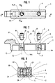
- Such a fitting 1 is intended to equip a door 2, window or the like comprising a groove 4 formed, in particular, in rebate 3 of its opening frame and / or of its sleeping frame.
- fasteners 5 which are in the form of at minus a needle screw 6 mounted in a through hole 8 said fitting 1.
- said orifice 8 decomposes, in the direction axial, in at least two portions 9, 9A of which the first 9 opens at the upper face 10 of said fitting 1, at the same place where said needle screw 6 is introduced in the latter.
- This first portion 9, in the direction of introduction of said screw 6, is frustoconical in shape while widening towards the mouth 12 of the orifice 8 for guiding this screw 6 towards the second portion 9A.
- This second portion 9A of the orifice 8 is located in the extension of the first portion 9, in the screwing direction of the needle screw 6. It has an inscribed diameter d less than the nominal diameter D of the screw 6 and opens at level of the lower face 11 of said fitting 1.
- this second portion 9A has a number of reservations 14A oriented axially along the axis 15 of the orifice 8. From such axial reservations 14A are, in fact, defined suitable for allow, by displacement of material inside these last, making a tapping 7 by said screw needle 6.
- the portion 9 has a section identical to that of the portion 9A facilitating the initiation 18 of the thread 7 by said screw needle 6, during the introduction and screwing of this last.
- the two portions 9 and 9A of the orifice 8 have a polygonal section, in particular hexagonal or octagonal, each side of the polygon of the second portion 9A is located in the extension of one side of the polygon of the first frustoconical portion 9.
- reservations 14A absorbs excess material repelled during realization of the internal thread 7 by a standard screw which is advantageously made of a metallic material, optionally stainless steel or hardened hard metal.
- such a needle screw 6 is preferably has the form of a grub screw 19, in particular with a hexagon socket or a slotted head, so as to facilitate its introduction into the orifice 8.
- FIG. 3 shows a fitting 1, according to the invention, immobilized inside a groove 4 in rebate 3 of a door 2, window or the like.
- the mounting such a fitting 1 consists, firstly, placing the latter inside said groove 4, then to intervene on the needle screw 6 so that the lower end 20 of the latter emerges out of the fitting 1 and comes into contact with the bottom 21 of the groove 4.
- said screw needle 6 pushes the fitting 1 towards the returns 22, 23 bordering the opening 24 of said groove 4 here “T” shaped. It is, more precisely, against these returns 22, 23 which then comes to bear on the upper face 10 of said fitting 1 for its immobilization.
- said needle screw 6 it can either be introduced into the orifice 8 after the fitting of the fitting 1 in the groove 4, either to be pre-assembled inside this orifice 8, for example during the manufacture of said fitting 1 or, at least, before the introduction of the latter inside the groove 4.
- a fitting 1 according to the invention can be made of a metallic material, in particular by molding, or a synthetic material, more especially PVC or the like.
- the present invention allows, on the one hand, to simplify the manufacture of such a fitting and, on the other hand, to resort to the use of a standard metal screw for its immobilization. This results in significant time savings as well as a substantial reduction in the cost price of a such hardware.
- the present invention therefore brings progress notable in the technical field considered.
Landscapes
- Engineering & Computer Science (AREA)
- General Engineering & Computer Science (AREA)
- Mechanical Engineering (AREA)
- Securing Of Glass Panes Or The Like (AREA)
- Connection Of Plates (AREA)
Description
- la figure 1 correspond à une vue schématisée et de dessus d'une ferrure selon l'invention ;
- la figure 2 est une vue schématisée, éclatée, en élévation et en coupe selon II - II de la ferrure représentée figure 1 ;
- la figure 3 correspond à une vue schématisée et en coupe selon III - III d'une telle ferrure immobilisée à l'intérieur d'une rainure en « T » ménagée en feuillure d'une porte, fenêtre ou analogue.
Claims (4)
- Ferrure pour porte (2), fenêtre ou analogue, du type ferrure de verrouillage, telle qu'une gâche, ferrure d'articulation ou autre, prévue apte à être immobilisée à l'intérieur d'une rainure (4) ménagée, notamment, en feuillure (3) du châssis ouvrant et/ou du cadre dormant de ladite porte (2), fenêtre ou analogue, à l'aide d'organes de fixation (5) sous forme de vis pointeau (6) aptes à coopérer avec un taraudage (7) ménagé dans un orifice (8) traversant ladite ferrure (1) et se décomposant, dans le sens axial, en au moins deux portions (9, 9A),
caractérisé par le fait que :la première portion (9) de l'orifice (8), dans le sens d'introduction de la vis (6), est de forme tronconique en allant en s'évasant vers l'embouchure (12) de l'orifice (8) pour assurer le guidage de cette vis (6) en direction de la seconde portion (9A) ;cette seconde portion (9A) de l'orifice (8) présente une section de forme polygonale et comporte, d'une part, un diamètre inscrit (d) inférieur au diamètre nominal (D) de la vis (6) et, d'autre part, des réservations axiales (14A) définies aptes à permettre, par déplacement de matière à l'intérieur de ces dernières, la réalisation dudit taraudage (7) par ladite vis pointeau (6), l'amorce (18) dudit taraudage (7) étant facilitée par une section de forme polygonale de la première portion (9) de l'orifice (8) ;les sections polygonales de la première (9) et de la seconde portion (9A) de l'orifice (8) sont identiques, chaque coté du polygone de la seconde portion (9A) se situant dans le prolongement d'un coté du polygone de la première portion tronconique (9). - Ferrure (1) selon la revendication 1, caractérisée par le fait que la section polygonale de la première (9) et de la seconde portion (9A) de l'orifice (8) est de forme hexagonale ou octogonale.
- Ferrure (1) selon l'une quelconque des revendications précédentes, caractérisée par le fait que ladite vis pointeau (6) est définie par une vis standard réalisée en un matériau métallique, éventuellement en inox ou dans un métal dur trempé.
- Ferrure (1) selon l'une quelconque des revendications précédentes, caractérisée par le fait que ladite vis pointeau (6) est une vis sans tête (19), notamment à six pas creux ou à tête fendue.
Priority Applications (3)
| Application Number | Priority Date | Filing Date | Title |
|---|---|---|---|
| DE69800142T DE69800142T2 (de) | 1998-05-06 | 1998-05-06 | Beschlag für Tür, Fenster o. dgl |
| ES98440083T ES2149042T3 (es) | 1998-05-06 | 1998-05-06 | Herraje para puerta, ventana o similar. |
| EP19980440083 EP0955429B1 (fr) | 1998-05-06 | 1998-05-06 | Ferrure pour porte, fenetre ou analogue |
Applications Claiming Priority (1)
| Application Number | Priority Date | Filing Date | Title |
|---|---|---|---|
| EP19980440083 EP0955429B1 (fr) | 1998-05-06 | 1998-05-06 | Ferrure pour porte, fenetre ou analogue |
Publications (2)
| Publication Number | Publication Date |
|---|---|
| EP0955429A1 EP0955429A1 (fr) | 1999-11-10 |
| EP0955429B1 true EP0955429B1 (fr) | 2000-05-10 |
Family
ID=8235675
Family Applications (1)
| Application Number | Title | Priority Date | Filing Date |
|---|---|---|---|
| EP19980440083 Expired - Lifetime EP0955429B1 (fr) | 1998-05-06 | 1998-05-06 | Ferrure pour porte, fenetre ou analogue |
Country Status (3)
| Country | Link |
|---|---|
| EP (1) | EP0955429B1 (fr) |
| DE (1) | DE69800142T2 (fr) |
| ES (1) | ES2149042T3 (fr) |
Families Citing this family (1)
| Publication number | Priority date | Publication date | Assignee | Title |
|---|---|---|---|---|
| CY2554B1 (fr) * | 2006-03-24 | 2008-07-02 | A C Technometal Ltd |
Family Cites Families (4)
| Publication number | Priority date | Publication date | Assignee | Title |
|---|---|---|---|---|
| GB815049A (en) * | 1956-12-13 | 1959-06-17 | Gen Motors Corp | Improvements in or relating to self-threading fastener devices, particularly threadable sockets of such devices |
| US4666055A (en) * | 1985-12-13 | 1987-05-19 | Harvey Hubbell Incorporated | Electrical outlet box with polygonal mounting bore |
| DE9110175U1 (de) * | 1991-08-16 | 1991-10-02 | Ferco International, Sarrebourg | Beschlagteil zur Klemmbefestigung in einer mindestens einseitig hinterschnittenen Profilnut |
| DE4431278A1 (de) * | 1994-09-02 | 1996-03-07 | Roto Frank Ag | Beschlagelementesatz für Fenster, Türen o. dgl. |
-
1998
- 1998-05-06 DE DE69800142T patent/DE69800142T2/de not_active Expired - Fee Related
- 1998-05-06 ES ES98440083T patent/ES2149042T3/es not_active Expired - Lifetime
- 1998-05-06 EP EP19980440083 patent/EP0955429B1/fr not_active Expired - Lifetime
Also Published As
| Publication number | Publication date |
|---|---|
| DE69800142D1 (de) | 2000-06-15 |
| EP0955429A1 (fr) | 1999-11-10 |
| ES2149042T3 (es) | 2000-10-16 |
| DE69800142T2 (de) | 2001-01-11 |
Similar Documents
| Publication | Publication Date | Title |
|---|---|---|
| EP0860615B1 (fr) | Pièce en matière plastique à fixation glissante intégrée | |
| FR2543629A1 (fr) | Boulon d'ancrage a expansion | |
| EP0952284A1 (fr) | Dispositif de verrouillage pour ouvrant coulissant | |
| EP0955429B1 (fr) | Ferrure pour porte, fenetre ou analogue | |
| EP0869244B1 (fr) | Ferrure à pêne réglable pour ouvrant coulissant | |
| FR3011572A3 (fr) | Ensemble de porte | |
| FR2476197A1 (fr) | Charniere de porte reglable | |
| FR2583837A1 (fr) | Douille d'espacement pour la fixation d'une ferrure sur un profil creux comportant une partie avancante | |
| EP0273841B1 (fr) | Gâche pour ouvrant coulissant de fenêtres, portes ou analogues | |
| FR2669383A1 (fr) | Ensemble de fixation a cheville encastrable. | |
| FR2868136A1 (fr) | Vis pour accrocher un profile creux en matiere plastique renforce par un profile metallique a une infrastructure | |
| CH623638A5 (en) | Self-tapping screw for fastening facia or cladding elements | |
| CA2237792C (fr) | Outillage pour le faconnage par emboutissage d'un orifice a embouchure tronconique | |
| EP1052357A1 (fr) | Elément de ferrure de type gâche | |
| FR2697279A1 (fr) | Dispositif de pivot central réglable à emboîtement et appareil pour monter une porte au moyen de ce dispositif. | |
| EP0654717A1 (fr) | Pièce d'horlogerie comportant un dispositif de fixation d'une pièce rapportée sur un bâti et procédé d'assemblage de cette pièce sur ledit bâti | |
| FR2502675A3 (fr) | Element de charniere | |
| FR2743388A1 (fr) | Fermeture encastrable a dispositif de verrouillage pour ouvrant de baie | |
| FR2465864A1 (fr) | Panneau pivotant a position reglable du pivot, notamment pour l'equipement d'une cabine de douche | |
| FR2793534A1 (fr) | Vis de fixation | |
| FR2816654A1 (fr) | Porte coulissante a serrure | |
| FR2735175A1 (fr) | Gond de reception d'une penture de volet, du type a axe rapporte | |
| FR2896020A1 (fr) | Dispositif de fixation et de reglage d'une piece sur un support | |
| FR2468711A1 (fr) | Protege-gond | |
| EP0377372B1 (fr) | Gache reglable destinée à êtré posée en applique, et serrure equipée d'une telle gache |
Legal Events
| Date | Code | Title | Description |
|---|---|---|---|
| GRAG | Despatch of communication of intention to grant |
Free format text: ORIGINAL CODE: EPIDOS AGRA |
|
| GRAG | Despatch of communication of intention to grant |
Free format text: ORIGINAL CODE: EPIDOS AGRA |
|
| GRAH | Despatch of communication of intention to grant a patent |
Free format text: ORIGINAL CODE: EPIDOS IGRA |
|
| PUAI | Public reference made under article 153(3) epc to a published international application that has entered the european phase |
Free format text: ORIGINAL CODE: 0009012 |
|
| 17P | Request for examination filed |
Effective date: 19981019 |
|
| AK | Designated contracting states |
Kind code of ref document: A1 Designated state(s): AT BE CH CY DE DK ES FI FR GB GR IE IT LI LU MC NL PT SE |
|
| AX | Request for extension of the european patent |
Free format text: AL;LT;LV;MK;RO;SI |
|
| GRAH | Despatch of communication of intention to grant a patent |
Free format text: ORIGINAL CODE: EPIDOS IGRA |
|
| GRAA | (expected) grant |
Free format text: ORIGINAL CODE: 0009210 |
|
| AK | Designated contracting states |
Kind code of ref document: B1 Designated state(s): DE ES FR GB IT |
|
| REG | Reference to a national code |
Ref country code: IE Ref legal event code: FG4D Free format text: FRENCH |
|
| REF | Corresponds to: |
Ref document number: 69800142 Country of ref document: DE Date of ref document: 20000615 |
|
| AKX | Designation fees paid |
Free format text: DE ES FR GB IT |
|
| ITF | It: translation for a ep patent filed | ||
| GBT | Gb: translation of ep patent filed (gb section 77(6)(a)/1977) |
Effective date: 20000803 |
|
| REG | Reference to a national code |
Ref country code: ES Ref legal event code: FG2A Ref document number: 2149042 Country of ref document: ES Kind code of ref document: T3 |
|
| REG | Reference to a national code |
Ref country code: IE Ref legal event code: FD4D |
|
| PLBE | No opposition filed within time limit |
Free format text: ORIGINAL CODE: 0009261 |
|
| STAA | Information on the status of an ep patent application or granted ep patent |
Free format text: STATUS: NO OPPOSITION FILED WITHIN TIME LIMIT |
|
| 26N | No opposition filed | ||
| REG | Reference to a national code |
Ref country code: GB Ref legal event code: IF02 |
|
| PGFP | Annual fee paid to national office [announced via postgrant information from national office to epo] |
Ref country code: GB Payment date: 20030507 Year of fee payment: 6 |
|
| PG25 | Lapsed in a contracting state [announced via postgrant information from national office to epo] |
Ref country code: GB Free format text: LAPSE BECAUSE OF NON-PAYMENT OF DUE FEES Effective date: 20040506 |
|
| GBPC | Gb: european patent ceased through non-payment of renewal fee |
Effective date: 20040506 |
|
| PGFP | Annual fee paid to national office [announced via postgrant information from national office to epo] |
Ref country code: FR Payment date: 20050503 Year of fee payment: 8 |
|
| PGFP | Annual fee paid to national office [announced via postgrant information from national office to epo] |
Ref country code: ES Payment date: 20050624 Year of fee payment: 8 |
|
| PGFP | Annual fee paid to national office [announced via postgrant information from national office to epo] |
Ref country code: DE Payment date: 20050720 Year of fee payment: 8 |
|
| PG25 | Lapsed in a contracting state [announced via postgrant information from national office to epo] |
Ref country code: ES Free format text: LAPSE BECAUSE OF NON-PAYMENT OF DUE FEES Effective date: 20060508 |
|
| PGFP | Annual fee paid to national office [announced via postgrant information from national office to epo] |
Ref country code: IT Payment date: 20060531 Year of fee payment: 9 |
|
| PG25 | Lapsed in a contracting state [announced via postgrant information from national office to epo] |
Ref country code: DE Free format text: LAPSE BECAUSE OF NON-PAYMENT OF DUE FEES Effective date: 20061201 |
|
| REG | Reference to a national code |
Ref country code: FR Ref legal event code: ST Effective date: 20070131 |
|
| REG | Reference to a national code |
Ref country code: ES Ref legal event code: FD2A Effective date: 20060508 |
|
| PG25 | Lapsed in a contracting state [announced via postgrant information from national office to epo] |
Ref country code: FR Free format text: LAPSE BECAUSE OF NON-PAYMENT OF DUE FEES Effective date: 20060531 |
|
| PG25 | Lapsed in a contracting state [announced via postgrant information from national office to epo] |
Ref country code: IT Free format text: LAPSE BECAUSE OF NON-PAYMENT OF DUE FEES Effective date: 20070506 |