EP0955439A2 - Cadre en bois - Google Patents
Cadre en bois Download PDFInfo
- Publication number
- EP0955439A2 EP0955439A2 EP99810375A EP99810375A EP0955439A2 EP 0955439 A2 EP0955439 A2 EP 0955439A2 EP 99810375 A EP99810375 A EP 99810375A EP 99810375 A EP99810375 A EP 99810375A EP 0955439 A2 EP0955439 A2 EP 0955439A2
- Authority
- EP
- European Patent Office
- Prior art keywords
- frame
- slot
- wooden
- slot space
- spaces
- Prior art date
- Legal status (The legal status is an assumption and is not a legal conclusion. Google has not performed a legal analysis and makes no representation as to the accuracy of the status listed.)
- Withdrawn
Links
- 239000002023 wood Substances 0.000 title claims description 7
- 239000000853 adhesive Substances 0.000 claims description 2
- 230000001070 adhesive effect Effects 0.000 claims description 2
- 239000007769 metal material Substances 0.000 claims 1
- 230000000149 penetrating effect Effects 0.000 claims 1
- 210000001503 joint Anatomy 0.000 description 4
- 238000004519 manufacturing process Methods 0.000 description 4
- 239000003292 glue Substances 0.000 description 3
- 230000035515 penetration Effects 0.000 description 3
- 238000004026 adhesive bonding Methods 0.000 description 2
- 230000004888 barrier function Effects 0.000 description 2
- 238000009500 colour coating Methods 0.000 description 2
- 238000009792 diffusion process Methods 0.000 description 2
- 238000007789 sealing Methods 0.000 description 2
- 239000007787 solid Substances 0.000 description 2
- 230000008961 swelling Effects 0.000 description 2
- 229910000831 Steel Inorganic materials 0.000 description 1
- 229920002522 Wood fibre Polymers 0.000 description 1
- 230000001788 irregular Effects 0.000 description 1
- 239000000463 material Substances 0.000 description 1
- 239000011120 plywood Substances 0.000 description 1
- 238000004080 punching Methods 0.000 description 1
- 239000010959 steel Substances 0.000 description 1
- 239000002025 wood fiber Substances 0.000 description 1
Images

Classifications
-
- E—FIXED CONSTRUCTIONS
- E06—DOORS, WINDOWS, SHUTTERS, OR ROLLER BLINDS IN GENERAL; LADDERS
- E06B—FIXED OR MOVABLE CLOSURES FOR OPENINGS IN BUILDINGS, VEHICLES, FENCES OR LIKE ENCLOSURES IN GENERAL, e.g. DOORS, WINDOWS, BLINDS, GATES
- E06B3/00—Window sashes, door leaves, or like elements for closing wall or like openings; Layout of fixed or moving closures, e.g. windows in wall or like openings; Features of rigidly-mounted outer frames relating to the mounting of wing frames
- E06B3/96—Corner joints or edge joints for windows, doors, or the like frames or wings
- E06B3/984—Corner joints or edge joints for windows, doors, or the like frames or wings specially adapted for frame members of wood or other material worked in a similar way
- E06B3/9845—Mitre joints
Definitions
- the invention relates to a wooden frame with the features of the preamble of claim 1.
- the invention has for its object to find a wooden frame of the type mentioned, which can be produced with relatively little effort and thus particularly economically and the frame parts are particularly resistant and permanently connected. This object is achieved according to the invention on the basis of the features of the characterizing part of patent claim 1.
- connection elements Due to these features, there is maximum engagement of large-area, flat connecting elements in the frame parts, with a correspondingly large gluing area, so that particularly high forces can be absorbed without additional metallic connecting means and opening of the miter joint by shrinkage or swelling forces of the wood is reliably prevented.
- a high durability of the connection also results from the fact that the connection elements form an internal diffusion barrier against the ingress of moisture beyond the immediate area of the butt joint, together with their adhesive surfaces on both sides.
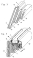
- the frame part 1 shown in the drawings of a e.g. Window frames milled from solid wood have an irregular shape of their cross-section formed by several appropriate gradations in order to create stop faces 2, 3 for the sealing contact with an outer frame anchored in masonry and to provide a recess 4 for the edge of insulating glazing 5.
- the other two slot spaces 10, 11, which are parallel to the former, are open to the inside of the wooden frame and are therefore only delimited by a narrow edge area 14, 15.
- the flat connecting elements 6 to 8 filling the slot spaces 9 to 11 thus also extend over almost the entire length of the oblique miter joint 16, so that penetration of the wooden frame along its butt joints 16 is prevented by moisture.
- This also illustrates the cross-sectional view parallel to the connecting element 6, corresponding to the representation in Figure 2.
- This illustration also shows, using the slot space 9 as an example, that the long, straight narrow side 17 of the slot spaces, which faces the adjacent outer surface 18 of the wooden frame, runs approximately parallel and with a slight inclination to the latter. A slight inclination according to the illustration in FIG.
- the slot space 9 is brought almost up to the frame corner and can thus be made particularly narrow, so that the flat connecting element 6 extends the butt joint along the butting surface 16 over almost its entire width closes and that a sufficiently thick or solid wall is nevertheless maintained to prevent the slot space 9 from being broken open by the pressure of the connecting element 6.
- the bottom surface 19 of the slot spaces 9 to 11 also runs essentially straight, but transversely to the frame part 1. In this way, the slot spaces 9 to 11 in the frame parts 1 have a large depth of penetration, so that in addition to a large-area diffusion barrier in the area of the miter joint 16 a large-area and thus high-strength gluing of the connecting elements 6 to 8 in the slot spaces 9 to 11 results.
- the deep slot spaces 9 to 11 are produced e.g. by a known caulking apparatus with a caulking tool attached to a rocker arm.
- the chiselling out of the bottom surface 19 of the slot spaces 9 to 11 must be carried out transversely to the direction of the wood fibers in a novel application of the caulking apparatus.
- the flat connecting elements 6 to 8 are preferably made of wood or plywood or of a material that is easy to glue to the wood of the frame 1. Their roughly square or angular contour can be easily produced by punching out.
- the gap 22 between the insulating glazing 5 and the frame part 1 is covered by a profile strip 23 which are held on the frame part 1 by strip holders 24. Sealing strips 25, 26 are also provided on both sides of the window pane 5.
- the invention has been described using an exemplary embodiment in which the abutting surfaces 16 extend at an angle of 45 ° to the longitudinal direction of the frame parts 1, so that one of the narrow sides 17 of the slot space 9 is considerably longer than the other narrow side 20.
- the abutting surfaces between two frame parts can, however, also run at a different angle or at right angles to the frame part 1.
- the slot spaces would have narrow sides 17, 20 of equal length, and the connecting element would extend as an elongate plate in a straight direction from one slot space to the other.
Landscapes
- Engineering & Computer Science (AREA)
- Civil Engineering (AREA)
- Structural Engineering (AREA)
- Joining Of Corner Units Of Frames Or Wings (AREA)
Applications Claiming Priority (2)
| Application Number | Priority Date | Filing Date | Title |
|---|---|---|---|
| DE19820125A DE19820125A1 (de) | 1998-05-06 | 1998-05-06 | Holzrahmen |
| DE19820125 | 1998-05-06 |
Publications (2)
| Publication Number | Publication Date |
|---|---|
| EP0955439A2 true EP0955439A2 (fr) | 1999-11-10 |
| EP0955439A3 EP0955439A3 (fr) | 2001-03-28 |
Family
ID=7866788
Family Applications (1)
| Application Number | Title | Priority Date | Filing Date |
|---|---|---|---|
| EP99810375A Withdrawn EP0955439A3 (fr) | 1998-05-06 | 1999-05-04 | Cadre en bois |
Country Status (2)
| Country | Link |
|---|---|
| EP (1) | EP0955439A3 (fr) |
| DE (1) | DE19820125A1 (fr) |
Citations (2)
| Publication number | Priority date | Publication date | Assignee | Title |
|---|---|---|---|---|
| DE1082726B (de) | 1958-04-12 | 1960-06-02 | Max Mayer | Stemmapparat zur Herstellung von schlitzfoermigen Aussparungen in Holzkoerpern |
| EP0271892A2 (fr) | 1986-12-17 | 1988-06-22 | Detlef Pandel | Joint d'angle à onglet de châssis de fenêtre en bois et dispositif pour la fabrication de celui-ci |
Family Cites Families (10)
| Publication number | Priority date | Publication date | Assignee | Title |
|---|---|---|---|---|
| DE642933C (de) * | 1937-03-19 | Karl Moertl | Eckverbindung fuer Holzrahmen, insbesondere Holzfensterrahmen | |
| DE810080C (de) * | 1949-10-14 | 1951-08-06 | Adolf Von Minden | Eckverbindung fuer Holzbauteile, beispielsweise fuer Fenster |
| DE815250C (de) * | 1949-12-18 | 1951-10-01 | Adolf Von Minden | Eckverbindung fuer Holzbauteile, beispielsweise fuer Fenster |
| DE862049C (de) * | 1951-04-03 | 1953-01-08 | Emil Stragies | Winkelduebel |
| CH340025A (de) * | 1958-07-15 | 1959-07-31 | Meyer Josef | Feder zum Verbinden von genuteten Gehrungsflächen an Holzgegenständen |
| US3502359A (en) * | 1967-11-24 | 1970-03-24 | Donald E Lucci | Jointing methods and means |
| GB2026125A (en) * | 1978-07-11 | 1980-01-30 | Hewitt M | Joint forming |
| IT1139843B (it) * | 1981-11-25 | 1986-09-24 | S I G E Srl | Serramento esterno per finestre e porte finestre in legno con qualisiasi movimento di apertura |
| BE903745A (fr) * | 1985-11-29 | 1986-03-14 | Turpin Daniel | Procede rapide et economique d'assemblage de profils. |
| DE9306791U1 (de) * | 1993-05-05 | 1993-09-30 | GEWE SELECTA Fenster- und Rolladenfabrik Heinrich Weihe GmbH & Co. KG, 32425 Minden | Rahmen, insbesondere Blend- und Flügelrahmen für Fenster |
-
1998
- 1998-05-06 DE DE19820125A patent/DE19820125A1/de not_active Withdrawn
-
1999
- 1999-05-04 EP EP99810375A patent/EP0955439A3/fr not_active Withdrawn
Patent Citations (2)
| Publication number | Priority date | Publication date | Assignee | Title |
|---|---|---|---|---|
| DE1082726B (de) | 1958-04-12 | 1960-06-02 | Max Mayer | Stemmapparat zur Herstellung von schlitzfoermigen Aussparungen in Holzkoerpern |
| EP0271892A2 (fr) | 1986-12-17 | 1988-06-22 | Detlef Pandel | Joint d'angle à onglet de châssis de fenêtre en bois et dispositif pour la fabrication de celui-ci |
Also Published As
| Publication number | Publication date |
|---|---|
| DE19820125A1 (de) | 1999-11-11 |
| EP0955439A3 (fr) | 2001-03-28 |
Similar Documents
| Publication | Publication Date | Title |
|---|---|---|
| DE69930674T2 (de) | Eckverbindung und verfahren zur herstellung einer derartigen eckverbindung | |
| DE202016002633U1 (de) | Spreizender Eckverbinder | |
| DE19613156C1 (de) | Bausatz für einen Fensterflügelrahmen aus Holz | |
| DE2053058A1 (de) | Rahmen mit als Hohlprofil ausgeführten Rahmenelementen | |
| AT392324B (de) | Waermegedaemmter fenster- oder tuerrahmen mit mindestens einem kaempferprofil | |
| EP3916188B1 (fr) | Dispositif de liaison permettant de relier deux composants dans la zone de butée d'une construction de porte ou de fenêtre, ainsi qu'un procédé de réalisation d'une telle liaison à onglets sur deux composants | |
| EP0955439A2 (fr) | Cadre en bois | |
| DE19900957A1 (de) | Eckverbinder für Hohlprofilrahmen von Fenstern und Türen | |
| DE2457940A1 (de) | Wandstaerkeneinstellbare tuerzarge | |
| DE60130085T2 (de) | Kunststoffflügel, sowie sein Herstellungsverfahren und zweiflügelige Öffnung, z.B. für ein Fenster | |
| CH544210A (de) | Rahmen aus Metallprofilen für Bauelemente in der Form von Türen, Fenstern und Wänden | |
| DE3809988C2 (de) | Profilstabförmiges Bauelement | |
| DE19944172B4 (de) | Rechteckfeld einer Rahmenfüllung | |
| DE1528345B2 (de) | Verbindungsleiste aus Kunststoff oder Metall zum Verbinden von zwei mit Holzleim zu verleimenden Holzteilen | |
| DE4041161A1 (de) | Verbindungsvorrichtung fuer eine sprossenkonstruktion und verfahren zur herstellung einer sprossenkonstruktion mit dieser verbindungsvorrichtung | |
| DE2163767C3 (de) | Verbindungselement in Form eines Bolzens zum Zusammenfügen von auf Gehrung geschnittenen Hohlprofilleisten für Türrahmen, Fensterrahmen oder dergleichen an den Rahmenecken | |
| AT412412B (de) | Adapterprofil | |
| DE3615486C2 (fr) | ||
| DE3606332A1 (de) | Verfahren zum verblenden von tuerzargen aus stahl sowie element zur verwendung bei diesem verfahren | |
| CH420567A (de) | Rahmenprofil für Fenster, Türen und dergleichen | |
| EP4112864A1 (fr) | Dispositif de liaison de sections d'onglet | |
| DE2739731A1 (de) | Eckwinkel, verfahren und vorrichtung zum verbinden der ecken von fenster- und tuerrahmen | |
| DE29801925U1 (de) | Kämpferverbinder | |
| EP4386167A1 (fr) | Profil d'aile | |
| EP4386168A1 (fr) | Profil d'aile avec fixation de ferrure |
Legal Events
| Date | Code | Title | Description |
|---|---|---|---|
| PUAI | Public reference made under article 153(3) epc to a published international application that has entered the european phase |
Free format text: ORIGINAL CODE: 0009012 |
|
| AK | Designated contracting states |
Kind code of ref document: A2 Designated state(s): AT BE CH CY DE DK ES FI FR GB GR IE IT LI LU MC NL PT SE |
|
| AX | Request for extension of the european patent |
Free format text: AL;LT;LV;MK;RO;SI |
|
| PUAL | Search report despatched |
Free format text: ORIGINAL CODE: 0009013 |
|
| AK | Designated contracting states |
Kind code of ref document: A3 Designated state(s): AT BE CH CY DE DK ES FI FR GB GR IE IT LI LU MC NL PT SE |
|
| AX | Request for extension of the european patent |
Free format text: AL;LT;LV;MK;RO;SI |
|
| AKX | Designation fees paid | ||
| REG | Reference to a national code |
Ref country code: DE Ref legal event code: 8566 |
|
| STAA | Information on the status of an ep patent application or granted ep patent |
Free format text: STATUS: THE APPLICATION IS DEEMED TO BE WITHDRAWN |
|
| 18D | Application deemed to be withdrawn |
Effective date: 20010929 |