EP0955444A2 - Procédé et dispositif pour l'installation d'un branchement domestique au moyen d'un forage dirigé - Google Patents
Procédé et dispositif pour l'installation d'un branchement domestique au moyen d'un forage dirigé Download PDFInfo
- Publication number
- EP0955444A2 EP0955444A2 EP99108573A EP99108573A EP0955444A2 EP 0955444 A2 EP0955444 A2 EP 0955444A2 EP 99108573 A EP99108573 A EP 99108573A EP 99108573 A EP99108573 A EP 99108573A EP 0955444 A2 EP0955444 A2 EP 0955444A2
- Authority
- EP
- European Patent Office
- Prior art keywords
- drill
- drilling
- building
- head
- cutter
- Prior art date
- Legal status (The legal status is an assumption and is not a legal conclusion. Google has not performed a legal analysis and makes no representation as to the accuracy of the status listed.)
- Withdrawn
Links
- 238000005553 drilling Methods 0.000 title claims abstract description 79
- 238000000034 method Methods 0.000 title claims description 35
- 239000011435 rock Substances 0.000 claims abstract description 23
- 239000002689 soil Substances 0.000 claims abstract description 5
- 239000012530 fluid Substances 0.000 claims description 4
- 238000004873 anchoring Methods 0.000 claims description 3
- 230000000750 progressive effect Effects 0.000 claims 1
- 238000009434 installation Methods 0.000 description 3
- 230000004323 axial length Effects 0.000 description 2
- 238000005516 engineering process Methods 0.000 description 2
- 239000000463 material Substances 0.000 description 2
- 230000005641 tunneling Effects 0.000 description 2
- 238000010521 absorption reaction Methods 0.000 description 1
- 238000009412 basement excavation Methods 0.000 description 1
- 230000005540 biological transmission Effects 0.000 description 1
- 238000005422 blasting Methods 0.000 description 1
- 238000003801 milling Methods 0.000 description 1
- 230000035515 penetration Effects 0.000 description 1
- XLYOFNOQVPJJNP-UHFFFAOYSA-N water Substances O XLYOFNOQVPJJNP-UHFFFAOYSA-N 0.000 description 1
Images

Classifications
-
- E—FIXED CONSTRUCTIONS
- E21—EARTH OR ROCK DRILLING; MINING
- E21B—EARTH OR ROCK DRILLING; OBTAINING OIL, GAS, WATER, SOLUBLE OR MELTABLE MATERIALS OR A SLURRY OF MINERALS FROM WELLS
- E21B10/00—Drill bits
- E21B10/36—Percussion drill bits
- E21B10/40—Percussion drill bits with leading portion
-
- E—FIXED CONSTRUCTIONS
- E21—EARTH OR ROCK DRILLING; MINING
- E21B—EARTH OR ROCK DRILLING; OBTAINING OIL, GAS, WATER, SOLUBLE OR MELTABLE MATERIALS OR A SLURRY OF MINERALS FROM WELLS
- E21B10/00—Drill bits
- E21B10/36—Percussion drill bits
- E21B10/38—Percussion drill bits characterised by conduits or nozzles for drilling fluids
-
- E—FIXED CONSTRUCTIONS
- E21—EARTH OR ROCK DRILLING; MINING
- E21B—EARTH OR ROCK DRILLING; OBTAINING OIL, GAS, WATER, SOLUBLE OR MELTABLE MATERIALS OR A SLURRY OF MINERALS FROM WELLS
- E21B10/00—Drill bits
- E21B10/60—Drill bits characterised by conduits or nozzles for drilling fluids
-
- E—FIXED CONSTRUCTIONS
- E21—EARTH OR ROCK DRILLING; MINING
- E21B—EARTH OR ROCK DRILLING; OBTAINING OIL, GAS, WATER, SOLUBLE OR MELTABLE MATERIALS OR A SLURRY OF MINERALS FROM WELLS
- E21B47/00—Survey of boreholes or wells
- E21B47/02—Determining slope or direction
- E21B47/022—Determining slope or direction of the borehole, e.g. using geomagnetism
- E21B47/0228—Determining slope or direction of the borehole, e.g. using geomagnetism using electromagnetic energy or detectors therefor
- E21B47/0232—Determining slope or direction of the borehole, e.g. using geomagnetism using electromagnetic energy or detectors therefor at least one of the energy sources or one of the detectors being located on or above the ground surface
-
- E—FIXED CONSTRUCTIONS
- E21—EARTH OR ROCK DRILLING; MINING
- E21B—EARTH OR ROCK DRILLING; OBTAINING OIL, GAS, WATER, SOLUBLE OR MELTABLE MATERIALS OR A SLURRY OF MINERALS FROM WELLS
- E21B7/00—Special methods or apparatus for drilling
- E21B7/04—Directional drilling
- E21B7/06—Deflecting the direction of boreholes
- E21B7/064—Deflecting the direction of boreholes specially adapted drill bits therefor
-
- E—FIXED CONSTRUCTIONS
- E21—EARTH OR ROCK DRILLING; MINING
- E21B—EARTH OR ROCK DRILLING; OBTAINING OIL, GAS, WATER, SOLUBLE OR MELTABLE MATERIALS OR A SLURRY OF MINERALS FROM WELLS
- E21B7/00—Special methods or apparatus for drilling
- E21B7/18—Drilling by liquid or gas jets, with or without entrained pellets
-
- E—FIXED CONSTRUCTIONS
- E21—EARTH OR ROCK DRILLING; MINING
- E21B—EARTH OR ROCK DRILLING; OBTAINING OIL, GAS, WATER, SOLUBLE OR MELTABLE MATERIALS OR A SLURRY OF MINERALS FROM WELLS
- E21B10/00—Drill bits
- E21B10/26—Drill bits with leading portion, i.e. drill bits with a pilot cutter; Drill bits for enlarging the borehole, e.g. reamers
-
- E—FIXED CONSTRUCTIONS
- E21—EARTH OR ROCK DRILLING; MINING
- E21B—EARTH OR ROCK DRILLING; OBTAINING OIL, GAS, WATER, SOLUBLE OR MELTABLE MATERIALS OR A SLURRY OF MINERALS FROM WELLS
- E21B10/00—Drill bits
- E21B10/42—Rotary drag type drill bits with teeth, blades or like cutting elements, e.g. fork-type bits, fish tail bits
Definitions
- the invention relates to a method for creating building connections by laying a line between a building and a main line and a device for performing the method. Furthermore, the invention relates to a drilling lance with which the method according to the invention can be carried out.
- a starting pit and a target pit which are also assembly pits.
- This situation is shown in Fig. 3.
- a front garden 14 or another area e.g. a terrace that should not be damaged if possible.
- a starting pit 18 is dug in the area of the main line 16 and a target pit 22 is created directly adjacent to the outer wall 20 of the building 10.
- This target pit is required because a masonry hole must be made in the building's basement of house 10 from the target pit.
- a special concrete drilling device such as a hammer drill or a drill saw must be used.
- a house connection machine is installed in the starting pit in the public street space in the methods in the prior art. The direction of advance is therefore basically from the road to the house.
- a course-controlled horizontal drilling has the advantage over the above-mentioned alternatives that the controllable drilling head is provided with a transmitting device and the position of the drilling head can be detected at any time via a locating device, with a directional correction being made in the event of an undesired deviation of the drilling head from the planned drilling process can be.
- Another advantage of a course-controlled drilling method is that even in the case of already known obstacles in the course between the connection point to the main line and the masonry passage, any sinuous and arched hole courses can be carried out.
- a compensating piece which is referred to as a curved armature, must be installed in front of the masonry passage in the target pit.
- This intermediate step can be omitted in the course-controlled horizontal drilling, but the accuracy of a completely course-controlled drilling is generally not sufficient to ensure that the course-controlled drilling is aligned with the masonry passage.
- the diameter of the house connection jacking is chosen so that it corresponds to the pipe cross-section to be drawn in. Therefore, after the house connection jacking has reached the target pit, the desired line can be pulled from the target pit to the starting pit by pulling back the house connection jacking.
- the invention has for its object a method and an apparatus for creating a house connection propose to avoid digging a target pit in the area of the desired masonry passage.
- the invention is based on the idea that the drilling direction, which is taken for granted in technology, is reversed from the street (starting pit) to the building and that all work steps can be carried out with a single device.
- a drill is used that can be installed in the building itself, especially in a basement.
- the device can clamp interchangeable drill heads and thus carry both a drill bit for drilling through the outer wall of the concrete and a completely course-controlled drill head. Therefore, the masonry passage no longer has to be created with a separate drill.
- the main advantage of the proposed method is, however, that it can be carried out without digging a pit on the outer wall of the building, since the masonry passage and the subsequent completely flow-controlled bore are automatically aligned by using a common drill.
- the fully flow-controlled drilling processes are relatively accurate, but it cannot be guaranteed that the Connection of lines with a diameter of only a few centimeters, a completely flow-controlled drilling carried out in the prior art to a masonry passage exactly achieved the desired goal.
- the drill pipe can be extended in segments while driving a completely course-controlled bore up to the main line, and the drill pipe can be removed again in segments during the pulling back of the drill pipe to the drill while the line is being pulled in.
- the remotely controllable drill head is replaced by an expansion head, in particular a reamer, before the line to be laid is connected to the drill pipe.
- the drilling device carries a drill carriage which can be arranged horizontally but also at an angle to the horizontally.
- drill carriage devices are generally heavier and larger in volume than core drilling systems, they do have the advantage that they enable rapid propulsion. This is particularly due to the fact that the method according to the invention is often used for Connection of complete residential areas to new supply lines is of great importance.
- the drill carriage preferably has a rack guide or the drill has push cylinders. Both alternatives allow very even propulsion.
- the drilling device can have a chain hoist, which also has the advantage of very uniform propulsion.
- the fastening device for fixing the position of the drilling device comprises at least one retaining anchor for anchoring the drilling device to the outer wall to be drilled through.
- This mounting alternative ensures the absorption of high horizontal forces when creating the masonry passage as well as when creating the completely gradient-controlled bore.
- the fastening device can comprise floor stands, so that elevation of the drilling device as well as anchoring to the outer wall to be drilled through is possible at the same time. Bracing between the floor slab and the basement ceiling is also possible.
- the newly developed drilling lance includes a transmitter device for locating the position of the drilling lance and a rock drill bit.
- the rock drill bit comprises a pre-cutter and at least one post-reamer, wherein the pre-cutter has a greater axial extent than the post-reamer (s). This means that when the drilling lance advances, the pre-cutter first comes into engagement with the soil structure to be penetrated.
- the reason for this asymmetrical design of the pre-cutter and of the post-clearer with respect to the axial length is that the pre-cutter fulfills the function as a control surface.
- flank cutters are additionally attached to the rock drill bit. These serve to convey the hard material backwards and smooth the borehole.
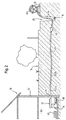
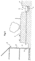
- the aim of the method is to lay a house connection line to house 10 from a connecting pit 28, which corresponds to the starting pit designated in the prior art with reference number 18 and in which the main line 16 is located, the line being intended to end in the basement area 30.
- the front yard 14 should remain completely undamaged.
- a drill 32 is first made in the basement 30. Since access to the basement areas in many single-family homes is via narrow, steep stairs, the drilling device 32 must be of a small size and, if possible, be disassembled into individual components in a simple and convenient manner so that it can be easily made in the basement area.
- the drill 32 has floor stands 34 so that it can be erected on the floor plate of the basement. Alternatively, a suitable attachment can also be doweled into the outer wall 20 of the building, as a result of which the drilling device can be anchored to the wall.
- the drilling device 32 should enable very uniform propulsion, which is possible, for example, by means of a rack and pinion guide or by using push cylinders.
- the appropriate drill should be selected.
- a drill can be used for lines with a larger cross-section or for a large installation length between the connection pit 28 and the house 10, which is horizontal but also angled bores can be arranged to the horizontal.
- easy-to-use core drilling machines with a low weight can also be used, the core drilling machine should be held in an angularly adjustable drill stand.
- An essential feature of the drilling device 32 used is that it can clamp and hold various drilling tools and enable their uncomplicated replacement.
- a concrete drill bit for creating the masonry culvert as well as remote-controlled drill heads for use in loose rock or rocky ground can be used, or a controllable drill bit with rock or concrete drill head tip as a newly developed device.
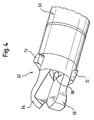
- This newly developed device is a drilling lance that consists of a rock core (two-wing cutter) with internal openings for high-pressure water jets in the head area.
- a transmitter In the remaining area of the drilling lance there is a transmitter and a battery compartment.
- the transmitter is used to precisely locate the position of the drilling lance during a completely course-controlled drilling.
- the steering and steering effect can be increased even further by designing the flight flanks on the drill head asymmetrically.
- a suitable collecting trough 36 must be provided which collects the drilling fluid.
- a suitable drill bit for example a concrete drill bit
- a remotely controllable drill head 38 which does not rotate, but by using High-pressure cutting blasting is advanced.
- the remotely controllable drill head 38 has a control surface inclined to the longitudinal axis of the bore and a transmitter installed in the region of the drill head, by means of which the position of the drill head can be determined with the aid of a locating device matched to the transmitter. With the aid of the locating device, the operating personnel, for example standing in the front yard 14, can determine the position of the drill head at any time and, in the event of a deviation from the desired drilling profile, carry out a directional correction.
- a drilling lance which is shown schematically in FIG. 4, has proven to be particularly suitable for carrying out the method when very hard rock floors are present.
- the drilling lance comprises a transmitter device 60, which is accommodated in the essentially cylindrical housing and cooperates with the locating device matched to the transmitter device in order to be able to control the desired drilling process.
- the drilling lance has a rock drill bit, which is generally designated by reference number 62.
- a pre-cutter 64 and a single post-clearer 66 are arranged on the rock drill bit.
- multi-wing cutters with more than one post-clearer can also be used.
- the pre-cutter 64 has a greater axial extent than the post-clearer 66, ie it extends further in the axial feed direction of the drilling lance than the reaming device 66.
- This has the advantage that the roughing cutter can be used as a control surface for the course-controlled guidance of the drilling lance.
- the pre-cutter is pivoted into the radial position in which the radially outer flank of the pre-cutter points in the direction of the desired outer radius of curvature of the desired directional correction. Because of the greater extent of the pre-cutter compared to the post-reamer, the pre-cutter takes the direction specified by the user and thus serves to steer the direction of the drilling lance.
- flank cutters 70 are additionally attached to the rock drill bit.
- the flank cutters 70 have a greater radial extension than the pre-cutter 64 as well as post-clearer 66 and serve to convey the hard, loosened material backwards in the direction of drilling advance, as well as to smooth the borehole.
- the provision of flank cutters is an optional measure and can also be omitted depending on the existing floor structure.
- the boring bar must be lengthened while the remote-controlled boring head is being driven.
- 40 individual boring bar segments are removed from a boring bar box and each attached to the already existing boring bar 42. 1 shows the individual drill rod segments 42a, 42b, 42c and the remotely controllable drill head 38.
- the drill head 38 is removed from the drill rod and the line 44 to be drawn in is fastened to the drill pipe.
- the connecting pit 28 can be made narrower than the starting pit 18 shown schematically in FIG. 3 because none House connection device or another suitable drill must find space in the connection pit. This further reduces the total excavation required.
- the line 44 to be drawn in can be removed from a suitable unwinding device in the area of the road 12. The drill pipe is then pulled back again, the individual drill pipe segments being deposited again in the drill pipe box 40. In this way, a line 44 to be drawn in can be drawn into the bore created between the basement area 30 and the connection pit 28, the line to be drawn in having essentially the same cross section as the remote-controlled drilling head.
- the aim is to make the drilling device 32, which must be brought into the basement area of the house, as small as possible. It is therefore advisable to work with a remotely controllable drill head and drill pipe with a very small diameter. If this diameter is smaller than the diameter of the line 44 to be drawn in, an expansion head 48 can be fastened between the drill pipe and the line 44 to be drawn in during the withdrawal of the drill pipe to the drilling device 32.
- An expanding head which can be designed in the form of a so-called reamers, has a conical geometry and can additionally be provided with abrasive elements on its surface.
- the expansion head 48 By pulling back the drill pipe, the expansion head 48, which is firmly attached to this, is also pulled in the direction of the house, so that the bore expands and the line 44, which is fastened to the expansion head and is fastened, can be pulled through the expanded bore to the house.
- the decisive advantage of the process is that the entire house connection line is completely controllable can and a target pit outside the house wall is basically omitted.
Landscapes
- Engineering & Computer Science (AREA)
- Mining & Mineral Resources (AREA)
- Geology (AREA)
- Life Sciences & Earth Sciences (AREA)
- Physics & Mathematics (AREA)
- Fluid Mechanics (AREA)
- Environmental & Geological Engineering (AREA)
- General Life Sciences & Earth Sciences (AREA)
- Geochemistry & Mineralogy (AREA)
- Mechanical Engineering (AREA)
- Geophysics (AREA)
- Electromagnetism (AREA)
- Processing Of Stones Or Stones Resemblance Materials (AREA)
- Excavating Of Shafts Or Tunnels (AREA)
Applications Claiming Priority (2)
| Application Number | Priority Date | Filing Date | Title |
|---|---|---|---|
| DE19820483A DE19820483C1 (de) | 1998-05-07 | 1998-05-07 | Verfahren und Vorrichtung zur Erstellung gesteuerter Hausanschlüsse |
| DE19820483 | 1998-05-07 |
Publications (2)
| Publication Number | Publication Date |
|---|---|
| EP0955444A2 true EP0955444A2 (fr) | 1999-11-10 |
| EP0955444A3 EP0955444A3 (fr) | 2002-09-25 |
Family
ID=7867008
Family Applications (1)
| Application Number | Title | Priority Date | Filing Date |
|---|---|---|---|
| EP99108573A Withdrawn EP0955444A3 (fr) | 1998-05-07 | 1999-05-06 | Procédé et dispositif pour l'installation d'un branchement domestique au moyen d'un forage dirigé |
Country Status (2)
| Country | Link |
|---|---|
| EP (1) | EP0955444A3 (fr) |
| DE (1) | DE19820483C1 (fr) |
Cited By (6)
| Publication number | Priority date | Publication date | Assignee | Title |
|---|---|---|---|---|
| WO2003001021A1 (fr) * | 2001-05-08 | 2003-01-03 | Tracto-Technik Gmbh | Procede de forage de roche |
| WO2004053285A1 (fr) * | 2002-12-06 | 2004-06-24 | Tracto-Technik Gmbh | Procede et dispositif pour forer des conduites |
| EP1803892A3 (fr) * | 2005-12-27 | 2010-01-13 | Beca Engineering S.r.l. | Procédé de déploiement rapide de tuyauterie/infrastructures/câblage pour services souterrains |
| CN101705788B (zh) * | 2009-08-31 | 2011-09-21 | 上海强劲地基工程股份有限公司 | 一种防喷塞掩护斜向钻孔的施工方法 |
| CN105804659A (zh) * | 2016-03-11 | 2016-07-27 | 柳超 | 一种用于钻深井的自动加强钻头 |
| AT18014U1 (de) * | 2022-10-12 | 2023-10-15 | Kirchsteiger Scheibmayr Gnbr | Befestigungsvorrichtung zur Aufnahme eines periodisch Schläge ausführenden Geräts auf einem Bohrständer |
Family Cites Families (12)
| Publication number | Priority date | Publication date | Assignee | Title |
|---|---|---|---|---|
| DE285283C (fr) * | ||||
| US3473616A (en) * | 1966-10-27 | 1969-10-21 | Forslund & Co Fabriks Ab | Rock-drill rig assembly |
| DE1811421A1 (de) * | 1968-11-28 | 1970-06-18 | Jakob Thaler | Verfahren zum Verlegen von Kabeln und Rohren in Fahrbahnkoerpern |
| GB1584888A (en) * | 1977-01-18 | 1981-02-18 | Salzgitter Maschinen Ag | Rock drilling apparatus |
| US4384624A (en) * | 1981-02-25 | 1983-05-24 | Duke John W | Earth boring head |
| GB2172225B (en) * | 1985-03-13 | 1989-09-06 | Dobson Park Ind | Drilling apparatus |
| NO873667L (no) * | 1987-09-01 | 1989-03-02 | Erik Hammer | Fremgangsmaate for fremfoering av hoeyspent-ledninger. |
| US4945999A (en) * | 1989-04-06 | 1990-08-07 | The Charles Machine Works, Inc. | Directional rod pusher |
| CH683016A5 (de) * | 1990-12-24 | 1993-12-31 | Terra Ag Tiefbautechnik | Verfahren zum Aufweiten eines Bohrloches und Aufweitgerät. |
| CH683116A5 (de) * | 1991-06-04 | 1994-01-14 | Peter Schenk | Vorrichtung zur grabenlosen Kabel- und Rohrverlegung. |
| US5282696A (en) * | 1992-10-30 | 1994-02-01 | Jim Solomon | Pneumatic ram pipe replacement |
| DE4423670A1 (de) * | 1994-06-23 | 1996-01-04 | Egon Dipl Ing Bannwarth | Wasserauffangvorrichtung für das Kühlwasser von Bohr- und Sägeeinrichtungen für Betonwände o. dgl. |
-
1998
- 1998-05-07 DE DE19820483A patent/DE19820483C1/de not_active Expired - Fee Related
-
1999
- 1999-05-06 EP EP99108573A patent/EP0955444A3/fr not_active Withdrawn
Non-Patent Citations (1)
| Title |
|---|
| None |
Cited By (8)
| Publication number | Priority date | Publication date | Assignee | Title |
|---|---|---|---|---|
| WO2003001021A1 (fr) * | 2001-05-08 | 2003-01-03 | Tracto-Technik Gmbh | Procede de forage de roche |
| WO2004053285A1 (fr) * | 2002-12-06 | 2004-06-24 | Tracto-Technik Gmbh | Procede et dispositif pour forer des conduites |
| GB2412935A (en) * | 2002-12-06 | 2005-10-12 | Tracto Technik | Method and device for drilling a channel |
| GB2412935B (en) * | 2002-12-06 | 2006-02-22 | Tracto Technik | Method and device for drilling a channel |
| EP1803892A3 (fr) * | 2005-12-27 | 2010-01-13 | Beca Engineering S.r.l. | Procédé de déploiement rapide de tuyauterie/infrastructures/câblage pour services souterrains |
| CN101705788B (zh) * | 2009-08-31 | 2011-09-21 | 上海强劲地基工程股份有限公司 | 一种防喷塞掩护斜向钻孔的施工方法 |
| CN105804659A (zh) * | 2016-03-11 | 2016-07-27 | 柳超 | 一种用于钻深井的自动加强钻头 |
| AT18014U1 (de) * | 2022-10-12 | 2023-10-15 | Kirchsteiger Scheibmayr Gnbr | Befestigungsvorrichtung zur Aufnahme eines periodisch Schläge ausführenden Geräts auf einem Bohrständer |
Also Published As
| Publication number | Publication date |
|---|---|
| DE19820483C1 (de) | 2000-04-27 |
| EP0955444A3 (fr) | 2002-09-25 |
Similar Documents
| Publication | Publication Date | Title |
|---|---|---|
| DE3782853T2 (de) | Verfahren und vorrichtung zum steuern der richtung eines schlagbohrwerkzeugs im bohrloch. | |
| EP3303753B1 (fr) | Système et procédé de pose près de la surface de câbles souterrains ou de conduites souterraines dans le sol | |
| EP2728104B1 (fr) | Procédé de réalisation d'un forage horizontal dans le sol et dispositif de forage horizontal | |
| DE60218282T2 (de) | Aufweitvorrichtung | |
| DE1634237A1 (de) | Verfahren zur Herstellung eines Zugankers im Erdboden | |
| DE3826513A1 (de) | Verfahren und rammbohrgeraet zum grabenlosen verlegen von versorgungsleitungen | |
| EP0548588B1 (fr) | Dispositif pour réaliser des forages dans le sol | |
| EP0860638B1 (fr) | Dispositif et procédé de pose de tubes céramiques sans excavation | |
| DE69926410T2 (de) | Bodenverstärkungsverfahren | |
| DE19820483C1 (de) | Verfahren und Vorrichtung zur Erstellung gesteuerter Hausanschlüsse | |
| EP2553203A2 (fr) | Dispositif de forage horizontal | |
| DE102011000320A1 (de) | Bohranlage zum Durchführen von Bohrungen im Erdreich | |
| DE19808478C2 (de) | Verfahren zum grabenlosen Verlegen von Rohren | |
| DE4006320C1 (en) | Straight line tunnel borer - has guide tube to which casing is connected with load-out conveyor | |
| DE10257392B4 (de) | Kanalbohrverfahren und -vorrichtung | |
| WO2014048627A2 (fr) | Dispositif et procédé de pose d'une canalisation dans un trou de forage | |
| EP1407112B1 (fr) | Procede permettant de realiser des sondages | |
| EP4144952B1 (fr) | Procédé de forage horizontal et système de forage horizontal | |
| DE10159712A1 (de) | Verfahren und Vorrichtung zum Herstellen von Erdbohrungen | |
| DE19946587A1 (de) | Vorrichtung zum Richtungsbohren | |
| EP3112580B1 (fr) | Procédé et dispositif pour la formation d'une canalisation souterraine | |
| DE2952593C2 (de) | Vorrichtung zum Einbringen von stangenförmigen Wärmetauschern in das Erdreich | |
| DE4413471C1 (de) | Verfahren zur Herstellung von liegenden und/oder geneigten, verfestigten Säulen im Baugrund sowie Vorrichtung zur Durchführung des Verfahrens nebst Anwendung | |
| DE10319800A1 (de) | Hohlbohrkrone für Kernbohrmaschinen | |
| DE19729882C1 (de) | Verfahren und Vorrichtung zum Herstellen eines Bohrpfahls |
Legal Events
| Date | Code | Title | Description |
|---|---|---|---|
| PUAI | Public reference made under article 153(3) epc to a published international application that has entered the european phase |
Free format text: ORIGINAL CODE: 0009012 |
|
| AK | Designated contracting states |
Kind code of ref document: A2 Designated state(s): AT BE CH CY DE DK ES FI FR GB GR IE IT LI LU MC NL PT SE |
|
| AX | Request for extension of the european patent |
Free format text: AL;LT;LV;MK;RO;SI |
|
| RIC1 | Information provided on ipc code assigned before grant |
Free format text: 7E 21B 7/06 A, 7E 21B 7/18 B, 7E 21B 10/38 B, 7E 21B 10/40 B, 7E 21B 10/42 B, 7E 21B 10/26 B, 7E 21B 10/60 B, 7E 21B 47/01 B, 7E 21B 7/28 B |
|
| PUAL | Search report despatched |
Free format text: ORIGINAL CODE: 0009013 |
|
| AK | Designated contracting states |
Kind code of ref document: A3 Designated state(s): AT BE CH CY DE DK ES FI FR GB GR IE IT LI LU MC NL PT SE |
|
| AX | Request for extension of the european patent |
Free format text: AL;LT;LV;MK;RO;SI |
|
| STAA | Information on the status of an ep patent application or granted ep patent |
Free format text: STATUS: THE APPLICATION HAS BEEN WITHDRAWN |
|
| AKX | Designation fees paid | ||
| 18W | Application withdrawn |
Effective date: 20030509 |
|
| REG | Reference to a national code |
Ref country code: DE Ref legal event code: 8566 |