EP0955501A2 - Four électrique de cuisson avec grilloir à gaz à rayonnement infrarouge - Google Patents
Four électrique de cuisson avec grilloir à gaz à rayonnement infrarouge Download PDFInfo
- Publication number
- EP0955501A2 EP0955501A2 EP99302651A EP99302651A EP0955501A2 EP 0955501 A2 EP0955501 A2 EP 0955501A2 EP 99302651 A EP99302651 A EP 99302651A EP 99302651 A EP99302651 A EP 99302651A EP 0955501 A2 EP0955501 A2 EP 0955501A2
- Authority
- EP
- European Patent Office
- Prior art keywords
- gas
- oven
- air mixture
- broiler
- venturi tube
- Prior art date
- Legal status (The legal status is an assumption and is not a legal conclusion. Google has not performed a legal analysis and makes no representation as to the accuracy of the status listed.)
- Withdrawn
Links
- 241000287828 Gallus gallus Species 0.000 title claims abstract description 48
- 238000010411 cooking Methods 0.000 title claims abstract description 27
- 239000007789 gas Substances 0.000 claims abstract description 99
- 239000000203 mixture Substances 0.000 claims abstract description 48
- 239000000919 ceramic Substances 0.000 claims abstract description 42
- 239000002737 fuel gas Substances 0.000 claims abstract description 34
- 238000002485 combustion reaction Methods 0.000 claims abstract description 29
- 238000010438 heat treatment Methods 0.000 claims description 29
- 239000000567 combustion gas Substances 0.000 claims 2
- 238000005485 electric heating Methods 0.000 abstract description 8
- 238000010792 warming Methods 0.000 abstract description 4
- 238000004140 cleaning Methods 0.000 abstract description 3
- ATUOYWHBWRKTHZ-UHFFFAOYSA-N Propane Chemical compound CCC ATUOYWHBWRKTHZ-UHFFFAOYSA-N 0.000 description 2
- 238000007599 discharging Methods 0.000 description 2
- VNWKTOKETHGBQD-UHFFFAOYSA-N methane Chemical compound C VNWKTOKETHGBQD-UHFFFAOYSA-N 0.000 description 2
- 238000007792 addition Methods 0.000 description 1
- 230000001010 compromised effect Effects 0.000 description 1
- 230000005611 electricity Effects 0.000 description 1
- 230000002708 enhancing effect Effects 0.000 description 1
- 239000000835 fiber Substances 0.000 description 1
- 239000002184 metal Substances 0.000 description 1
- 238000012986 modification Methods 0.000 description 1
- 230000004048 modification Effects 0.000 description 1
- 239000003345 natural gas Substances 0.000 description 1
- 230000002028 premature Effects 0.000 description 1
- 239000001294 propane Substances 0.000 description 1
- 238000006467 substitution reaction Methods 0.000 description 1
- 238000013022 venting Methods 0.000 description 1
Images

Classifications
-
- F—MECHANICAL ENGINEERING; LIGHTING; HEATING; WEAPONS; BLASTING
- F24—HEATING; RANGES; VENTILATING
- F24C—DOMESTIC STOVES OR RANGES ; DETAILS OF DOMESTIC STOVES OR RANGES, OF GENERAL APPLICATION
- F24C15/00—Details
- F24C15/32—Arrangements of ducts for hot gases, e.g. in or around baking ovens
- F24C15/322—Arrangements of ducts for hot gases, e.g. in or around baking ovens with forced circulation
-
- A—HUMAN NECESSITIES
- A47—FURNITURE; DOMESTIC ARTICLES OR APPLIANCES; COFFEE MILLS; SPICE MILLS; SUCTION CLEANERS IN GENERAL
- A47J—KITCHEN EQUIPMENT; COFFEE MILLS; SPICE MILLS; APPARATUS FOR MAKING BEVERAGES
- A47J27/00—Cooking-vessels
- A47J27/08—Pressure-cookers; Lids or locking devices specially adapted therefor
- A47J27/086—Pressure-cookers; Lids or locking devices specially adapted therefor with built-in heating means
-
- F—MECHANICAL ENGINEERING; LIGHTING; HEATING; WEAPONS; BLASTING
- F24—HEATING; RANGES; VENTILATING
- F24C—DOMESTIC STOVES OR RANGES ; DETAILS OF DOMESTIC STOVES OR RANGES, OF GENERAL APPLICATION
- F24C3/00—Stoves or ranges for gaseous fuels
- F24C3/08—Arrangement or mounting of burners
- F24C3/085—Arrangement or mounting of burners on ranges
- F24C3/087—Arrangement or mounting of burners on ranges in baking ovens
-
- Y—GENERAL TAGGING OF NEW TECHNOLOGICAL DEVELOPMENTS; GENERAL TAGGING OF CROSS-SECTIONAL TECHNOLOGIES SPANNING OVER SEVERAL SECTIONS OF THE IPC; TECHNICAL SUBJECTS COVERED BY FORMER USPC CROSS-REFERENCE ART COLLECTIONS [XRACs] AND DIGESTS
- Y02—TECHNOLOGIES OR APPLICATIONS FOR MITIGATION OR ADAPTATION AGAINST CLIMATE CHANGE
- Y02B—CLIMATE CHANGE MITIGATION TECHNOLOGIES RELATED TO BUILDINGS, e.g. HOUSING, HOUSE APPLIANCES OR RELATED END-USER APPLICATIONS
- Y02B40/00—Technologies aiming at improving the efficiency of home appliances, e.g. induction cooking or efficient technologies for refrigerators, freezers or dish washers
Definitions
- This invention relates to cooking ovens and, in particular, cooking ovens that have plural operating modes including broiling and baking.
- the present invention provides a cooking oven comprising,
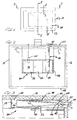
- the oven is shown diagrammatically as an oven cell with six insulated and closed walls, namely, a top wall 12, a bottom wall 14, a right side wall 16, a left side wall 18, a rear wall 20 and a front wall 22.
- the front wall 22 is provided with a conventional door 24 that is tightly sealed in the door opening 25 in the front wall 22 when the door 24 is closed, in a conventional manner common to electric ovens.
- the top wall 12, bottom wall 14, right side wall 16 and left side wall 18 are completely closed, as are the joints between all of the walls, whereby no inefficient exchange of air between the inside and the outside of the oven 10 occurs through those walls and joints.
- the rear wall 20 has only those openings that are required for the operating components of the oven 10.
- An electric heating element 26 is provided in the bottom of the interior of the oven 10 in a conventional manner for heating the interior of the oven during conventional modes of operation, such as preheating, warming, baking, high temperature cleaning and the like.
- the interior of each of the side walls 16 and 18 is provided with a conventional grate rack 28 for supporting a rod type grate 30 at any desired level within the oven for in turn supporting a pan 32 or the like for receiving the food to be cooked.
- a gas broiler, generally designated 34, is provided on the upper interior surface of the oven and attached to top wall 12.
- Gas broiler 34 is preferably of the infrared burner type having ceramic radiants 36, three of which are shown for this size oven, that are thin ceramic tile-like elements with a multiplicity of small holes 38 extending vertically therethrough which allows a mixture of fuel gas and air to pass downwardly through the ceramic radiants 36 and burn along the bottom surface of the radiants 36.
- the gas/air combustion extends over substantially the entire lower surfaces of the ceramic radiants 36 to thereby heat the ceramic radiants to temperatures of about 1600°F.
- the heated ceramic radiants create infrared light waves that peak at about 2.8 microns and radiate downwardly in all directions from the ceramic radiants 36 to evenly heat and broil food items placed in the oven pan 32.
- the combustion of the fuel gas/air mixture along the bottom surface of the ceramic radiants 36 is very even and continuous during broiling and therefore the intensity of the broiling action on the food is adjusted by adjusting the distance of the food from the ceramic radiants 36, such as by using different levels of support for the grate 30 on the grate racks 28.
- the infrared gas broiler 34 includes a venturi tube assembly, generally designated 40, comprised of a cylindrical outer tube 42, a long frustoconical tube 43, a short frustoconical tube 44 and a gas jet fitting 45.
- the long frustoconical tube 43 and the short frustoconical tube 44 are joined at their smaller, open ends to form a venturi opening or orifice 46 through which the fuel gas is discharged from the gas jet fitting 45 by a jet opening 47 to thereby draw primary air into the venturi tube assembly 40 through the rear opening 48 in the cylindrical tube 42.
- the venturi tube assembly 40 is of a substantial length and the long frustoconical tube 43 preferably has a very small angle of inclination of its sides, such as about 2 degrees.
- a substantially stoichiometric mixture of fuel gas and air is created in the long frustoconical tube 43, which mixture will then burn completely and efficiently in the combustion that occurs on the lower surface of the ceramic radiants 36.
- the fuel gas may be natural gas, propane or any other appropriate gas at an appropriate pressure for producing the desired gas/air mixture and flow in the gas broiler 34.
- the fuel gas is supplied through a line 49 in a conventional manner.
- the gas broiler 34 includes a plenum 50 formed by a box formed above and around the ceramic radiants 36, which box also supports the ceramic radiants 36.
- the venturi tube assembly 40 extends into the plenum 50 and the outer cylindrical tube 42 is in sealed relationship with an opening 52 in the box forming the plenum 50.
- An L-shaped baffle 54 is provided at the discharge end 56 of the venturi tube assembly 40 for more evenly distributing the gas/air mixture into the plenum 50. Additional baffles may be provided in plenum 50 at appropriate locations for enhancing the even distribution of the gas/air mixture to all of the holes 38 in the ceramic radiants 36.
- the venturi tube assembly 40 with the jet of fuel gas from gas jet fitting 45 creates a positive pressure in plenum 50 that is higher than atmospheric pressure, thereby forcing the gas/air mixture through the holes 38 in the ceramic radiants 36 in a substantially even manner which produces a substantially even sheet of flame along the bottom surface of the ceramic radiants 36.
- the perimeters of the ceramic radiants 36 are sealed to each other and the box by gaskets, such as ceramic fiber gaskets, for assuring that the gas/air mixture flows only through the holes 38.
- An igniter 60 is provided immediately below one of the ceramic radiants 36 for igniting the gas/air mixture.
- the igniter 60 is a hot surface type igniter having an electrical resistance wire positioned close to the bottom surface of the ceramic radiant 36, although other types of igniters may be used, such as a spark igniter.
- the resistance wire of igniter 60 is maintained in a red hot condition continually while the gas broiler 34 is in operation to assure that the gas/air mixture is continually ignited or reignited if the flame is inadvertently extinguished. As shown in Fig. 2, it is preferable that the igniter 60 be spaced laterally from the venturi tube assembly 40 to avoid unduly heating the venturi tube assembly.
- the electric heating element 26 and the gas broiler 34 are provided with separate controls (not shown) of a conventional type such that when the electric heating element 26 is energized, the gas broiler 34 is shut-off and conversely when the gas broiler 34 is activated, the electric heating element 26 is off.
- a conventional temperature control can be provided in connection with the electric heating element 26 for controlling the temperature of the entire oven to the desired level during baking or warming.
- a temperature control may also be provided with the gas broiler 34 to prevent an excessively high temperature in the oven but normally the broiling mode will be continued at the highest temperature that the gas broiler 34 can produce until broiling of the food item is completed.
- the fuel gas from line 49 will be discharged through the opening 47 of gas jet fitting 45 into the orifice 46 in the venturi tube assembly 40 to draw in fresh air through the opening in the open end 48 of the tube 42 extending through the rear wall 20 and the gas/air mixture is discharged from the venturi tube assembly 40 into the plenum 50 to create a positive pressure to force the gas/air mixture evenly through all of the holes 38 in the ceramic radiants 36.
- the control for starting the operation of the gas broiler 34 also energizes the igniter 60 for igniting the gas/air mixture being discharged downwardly through the holes 38 in the ceramic radiants 36, whereby the combustion raises the temperature of the ceramic radiants to about l600°F for producing infrared light rays for broiling.
- the discharge of the gas/air mixture through the holes 38 and the combustion creates a positive pressure in the interior of the oven pan that is higher than atmospheric pressure.
- the combusted gases and heated air from within the oven rise to the top and are forced through an opening 62 in the top of the rear wall 20 into a vent pipe or flue duct 64 to the outside, as shown by arrows A in Fig. 4.
- the positive pressure created by the venturi tube assembly 40 and combustion of the gas/air mixture produces a forced natural draft for the hot gases to be discharged through the flue duct 64, both because the gases are hotter than the ambient temperature and the internal pressure in the oven is higher than atmospheric pressure.
- the ceramic radiants 36 also serve to thermally insulate the plenum 50 from the flames to thereby prevent premature combustion of the gas/air mixture in the plenum.
- the oven 10 may also be provided with a conventional convection oven assembly, generally designated 70, on the rear wall 20.
- the convection oven assembly 70 includes a fan 71 driven by an electric motor 72 and surrounded by a heating element 73 for drawing air from the interior of the oven through a metal screen filter 74 mounted in the front of an enclosure 75 and discharging that air back into the oven from the right and left ends of the enclosure 75, as shown by arrows C in Fig. 2.
- the convection oven assembly 70 would be selectively operable when the oven is being used for baking with the electric heating element 26 energized but it may also be desirable to activate the convection oven assembly 70 during some food broiling operations when the gas broiler 34 is in operation.
- the present invention provides a cooking oven that combines an infrared gas broiler in an otherwise electrically heated oven; and furthermore provides a combination infrared gas broiler and electric oven which is completely closed except for the introduction of primary air with the fuel gas for combustion and a flue for venting the combusted gases, whereby secondary air is not permitted to flow through the oven to cause inefficiencies.
Landscapes
- Engineering & Computer Science (AREA)
- Chemical & Material Sciences (AREA)
- Combustion & Propulsion (AREA)
- Mechanical Engineering (AREA)
- General Engineering & Computer Science (AREA)
- Food Science & Technology (AREA)
- Baking, Grill, Roasting (AREA)
- Electric Stoves And Ranges (AREA)
- Resistance Heating (AREA)
Applications Claiming Priority (2)
| Application Number | Priority Date | Filing Date | Title |
|---|---|---|---|
| US55977 | 1998-04-06 | ||
| US09/055,977 US5909533A (en) | 1998-04-06 | 1998-04-06 | Electric cooking oven with infrared gas broiler |
Publications (2)
| Publication Number | Publication Date |
|---|---|
| EP0955501A2 true EP0955501A2 (fr) | 1999-11-10 |
| EP0955501A3 EP0955501A3 (fr) | 2001-09-12 |
Family
ID=22001343
Family Applications (1)
| Application Number | Title | Priority Date | Filing Date |
|---|---|---|---|
| EP99302651A Withdrawn EP0955501A3 (fr) | 1998-04-06 | 1999-04-06 | Four électrique de cuisson avec grilloir à gaz à rayonnement infrarouge |
Country Status (7)
| Country | Link |
|---|---|
| US (1) | US5909533A (fr) |
| EP (1) | EP0955501A3 (fr) |
| JP (1) | JP2000028142A (fr) |
| KR (1) | KR100326963B1 (fr) |
| AU (1) | AU739705B2 (fr) |
| BR (1) | BR9903050A (fr) |
| CA (1) | CA2267869A1 (fr) |
Cited By (2)
| Publication number | Priority date | Publication date | Assignee | Title |
|---|---|---|---|---|
| CN109452880A (zh) * | 2018-12-25 | 2019-03-12 | 江苏光芒电器有限责任公司 | 一种使用木质为燃料的烤炉及使用方法 |
| CN109730545A (zh) * | 2019-03-22 | 2019-05-10 | 珠海飞龙电器有限公司 | 多功能烤炉 |
Families Citing this family (28)
| Publication number | Priority date | Publication date | Assignee | Title |
|---|---|---|---|---|
| US6222163B1 (en) * | 1999-10-13 | 2001-04-24 | Maytag Corporation | Gas oven incorporating auxiliary electric heating element |
| NL1014044C2 (nl) * | 2000-01-10 | 2001-07-19 | Levens Group B V | Door gasbrander verwarmde oven. |
| IT1315481B1 (it) * | 2000-07-25 | 2003-02-18 | Gierre Srl | Forno a convezione forzata per la cottura di alimenti |
| US6776151B2 (en) * | 2001-08-21 | 2004-08-17 | Distinctive Appliances, Inc. | Positive air flow apparatus for infrared gas broiler |
| US6943324B2 (en) * | 2003-04-10 | 2005-09-13 | Maytag Corporation | Combination heating system for a cooking appliance |
| US7335858B2 (en) * | 2003-12-18 | 2008-02-26 | Applica Consumer Products, Inc. | Toaster using infrared heating for reduced toasting time |
| US7619186B2 (en) * | 2004-02-10 | 2009-11-17 | Applica Consumer Products, Inc. | Intelligent user interface for multi-purpose oven using infrared heating for reduced cooking time |
| US7323663B2 (en) | 2004-02-10 | 2008-01-29 | Applica Consumer Products, Inc. | Multi-purpose oven using infrared heating for reduced cooking time |
| EP1742555A4 (fr) * | 2004-04-30 | 2010-03-24 | Salton | Appareil de cuisson electrique a plaques chauffantes amovibles et procede d'utilisation associe |
| US7759617B2 (en) * | 2004-11-03 | 2010-07-20 | General Electric Company | Gas range and method for using the same |
| WO2008060443A2 (fr) | 2006-11-10 | 2008-05-22 | Best Willie H | Rôtissoire à tube radiant |
| US20090250451A1 (en) * | 2008-04-03 | 2009-10-08 | Electrolux Home Products Inc. | Auto stir |
| US8578265B2 (en) * | 2008-10-07 | 2013-11-05 | Bigmachines, Inc. | Methods and apparatus for generating a dynamic document |
| US9524506B2 (en) | 2011-10-21 | 2016-12-20 | Bigmachines, Inc. | Methods and apparatus for maintaining business rules in a configuration system |
| DE102008053145A1 (de) * | 2008-10-24 | 2010-04-29 | Rational Ag | Strömungsleitvorrichtung für ein Gargerät |
| WO2010135146A1 (fr) * | 2009-05-18 | 2010-11-25 | Tamperproof Container Licensing Corp. | Système de détection de fuite nucléaire par liaison filaire ou par fibre optique |
| US20110067577A1 (en) * | 2009-09-18 | 2011-03-24 | Riddle Brian S | Cooktop griddle and broiler for cooking appliances |
| CN102379319B (zh) * | 2010-09-06 | 2015-01-07 | 宁波高博科技有限公司 | 红外线燃气烧烤炉 |
| CN103876643A (zh) * | 2012-12-21 | 2014-06-25 | 刘智辉 | 一种由导流板组成的双腔燃气烤箱 |
| US9510604B2 (en) | 2013-06-17 | 2016-12-06 | W.C. Bradley Co. | Outdoor cooker and smoker, and fuel combustor therefor |
| CA2914844A1 (fr) | 2013-06-17 | 2014-12-24 | W.C. Bradley Co. | Appareil et procede de cuisson, de chauffage et de sechage a rendement eleve |
| CN105979782B (zh) | 2013-12-16 | 2020-08-18 | 德卢卡烤炉技术有限责任公司 | 用于丝网加热元件和编织成角度的丝网的连续更新系统 |
| US9709281B2 (en) | 2014-03-31 | 2017-07-18 | W.C. Bradley Co. | High efficiency side burner and outdoor cooker |
| US10203108B2 (en) | 2014-08-14 | 2019-02-12 | De Luca Oven Technologies, Llc | Vapor generator including wire mesh heating element |
| EP3273786B8 (fr) | 2015-03-25 | 2020-03-04 | W.C. Bradley Co. | Cuiseur et fumoir électrique vertical avec boîte à fumée |
| CN109480652A (zh) * | 2018-12-06 | 2019-03-19 | 中山市凌锐五金制品有限公司 | 一种烧烤炉 |
| US20220154934A1 (en) * | 2020-11-13 | 2022-05-19 | Haier Us Appliance Solutions, Inc. | Oven appliance with top gas burner |
| CN119817971B (zh) * | 2025-01-15 | 2025-11-04 | 广东志美尼电器有限公司 | 一种节气型电子燃气烤炉 |
Family Cites Families (12)
| Publication number | Priority date | Publication date | Assignee | Title |
|---|---|---|---|---|
| US1495685A (en) * | 1920-11-09 | 1924-05-27 | Graf Franz | Oven and electric heater therefor |
| US1475608A (en) * | 1922-11-01 | 1923-11-27 | Buck S Stove & Range Company | Combination gas and electric stove |
| US1815088A (en) * | 1929-07-04 | 1931-07-21 | Allen George William | Gas oven electric heater |
| US2463712A (en) * | 1945-03-21 | 1949-03-08 | Robert E Newell | Method of oven heating and control |
| US2969450A (en) * | 1959-02-16 | 1961-01-24 | Samuel M Bernstein | Portable combination electric rotisserie and charcoal broiler |
| US3157390A (en) * | 1961-04-03 | 1964-11-17 | Blackstone Corp | Combination gas and electric heater for a clothes drier |
| US3423568A (en) * | 1966-08-22 | 1969-01-21 | Tappan Co The | Electric and gas self-cleaning oven |
| DE3261366D1 (en) * | 1981-06-16 | 1985-01-10 | Pierre Nibelle | Gas oven for baking, cooking and grilling food |
| GB2105459B (en) * | 1981-09-05 | 1984-11-21 | Cannon Ind Ltd | Dual function cooking oven |
| US4671250A (en) * | 1986-07-28 | 1987-06-09 | Thermo Electron Corporation | Direct-firing gas convection oven |
| GB2270750B (en) * | 1992-09-11 | 1996-08-14 | Stoves Ltd | Improvements in and relating to gas-fired cooking appliances |
| IT1274912B (it) * | 1994-09-23 | 1997-07-25 | Reynolds Wheels Int Ltd | Metodo ed impianto per portare allo stato semisolido o semiliquido masselli in lega metallica quali lingotti, billette e simili, da sottoporre a formatura tixotropica. |
-
1998
- 1998-04-06 US US09/055,977 patent/US5909533A/en not_active Expired - Lifetime
-
1999
- 1999-03-31 CA CA002267869A patent/CA2267869A1/fr not_active Abandoned
- 1999-04-01 AU AU23536/99A patent/AU739705B2/en not_active Ceased
- 1999-04-03 KR KR1019990011786A patent/KR100326963B1/ko not_active Expired - Fee Related
- 1999-04-06 BR BR9903050-0A patent/BR9903050A/pt not_active Application Discontinuation
- 1999-04-06 EP EP99302651A patent/EP0955501A3/fr not_active Withdrawn
- 1999-04-06 JP JP11098721A patent/JP2000028142A/ja active Pending
Cited By (3)
| Publication number | Priority date | Publication date | Assignee | Title |
|---|---|---|---|---|
| CN109452880A (zh) * | 2018-12-25 | 2019-03-12 | 江苏光芒电器有限责任公司 | 一种使用木质为燃料的烤炉及使用方法 |
| CN109452880B (zh) * | 2018-12-25 | 2022-02-08 | 江苏光芒电器有限责任公司 | 一种使用木质为燃料的烤炉及使用方法 |
| CN109730545A (zh) * | 2019-03-22 | 2019-05-10 | 珠海飞龙电器有限公司 | 多功能烤炉 |
Also Published As
| Publication number | Publication date |
|---|---|
| AU739705B2 (en) | 2001-10-18 |
| KR100326963B1 (ko) | 2002-03-13 |
| US5909533A (en) | 1999-06-01 |
| AU2353699A (en) | 1999-10-14 |
| CA2267869A1 (fr) | 1999-10-06 |
| BR9903050A (pt) | 2000-01-18 |
| JP2000028142A (ja) | 2000-01-25 |
| EP0955501A3 (fr) | 2001-09-12 |
| KR19990087889A (ko) | 1999-12-27 |
Similar Documents
| Publication | Publication Date | Title |
|---|---|---|
| US5909533A (en) | Electric cooking oven with infrared gas broiler | |
| US6776151B2 (en) | Positive air flow apparatus for infrared gas broiler | |
| EP2348934B1 (fr) | Brûleur à tubes parallèles à refroidissement amélioré et taille réduite | |
| US4598691A (en) | Gas oven with recessed broil burner | |
| EP1089646B1 (fr) | Ensemble de chauffage et appareil de cuisson | |
| USRE29602E (en) | Domestic oven | |
| WO1992017739A1 (fr) | Cheminee a gas possedant un rendement thermique eleve | |
| US6098613A (en) | Venting system for gas oven | |
| CA1302816C (fr) | Appareil de cuisson a gaz | |
| KR101564844B1 (ko) | 고효율 펠릿 난로 | |
| CN1240910A (zh) | 具有红外气体烧烤器的电烹调炉 | |
| US20020157659A1 (en) | Gas broiler | |
| JP2000245624A (ja) | ガスグリル | |
| JP2757516B2 (ja) | ガス調理器 | |
| MXPA99003263A (es) | Horno de coccion electrico con asador de gas y de ondas de luz infrarroja | |
| HK1028275A (en) | Electric cooking oven with an ultra-red gas grilling device | |
| US436656A (en) | Gas-stove | |
| KR101710202B1 (ko) | 가스 오븐레인지 | |
| JPH0774687B2 (ja) | ガス燃焼装置およびガス加熱調理器 | |
| GB2280747A (en) | Oil or gas-burning stove | |
| WO2003040626A1 (fr) | Four a convection presentant une bruleur a gaz | |
| US9897323B2 (en) | Gas oven | |
| JP2001340231A (ja) | グリル | |
| JPH0718538B2 (ja) | バーナ装置 |
Legal Events
| Date | Code | Title | Description |
|---|---|---|---|
| PUAI | Public reference made under article 153(3) epc to a published international application that has entered the european phase |
Free format text: ORIGINAL CODE: 0009012 |
|
| AK | Designated contracting states |
Kind code of ref document: A2 Designated state(s): AT BE CH CY DE DK ES FI FR GB GR IE IT LI LU MC NL PT SE Kind code of ref document: A2 Designated state(s): DE FR GB |
|
| AX | Request for extension of the european patent |
Free format text: AL;LT;LV;MK;RO;SI |
|
| RIN1 | Information on inventor provided before grant (corrected) |
Inventor name: GENGXIN, FENG Inventor name: ADAMS, CARL H. Inventor name: DELGADO, HUMBERTO Inventor name: KITABAYASHI, JOEY |
|
| RAP1 | Party data changed (applicant data changed or rights of an application transferred) |
Owner name: DISTINCTIVE APPLIANCES, INC |
|
| PUAL | Search report despatched |
Free format text: ORIGINAL CODE: 0009013 |
|
| AK | Designated contracting states |
Kind code of ref document: A3 Designated state(s): AT BE CH CY DE DK ES FI FR GB GR IE IT LI LU MC NL PT SE |
|
| AX | Request for extension of the european patent |
Free format text: AL;LT;LV;MK;RO;SI |
|
| 17P | Request for examination filed |
Effective date: 20020220 |
|
| AKX | Designation fees paid |
Free format text: DE FR GB |
|
| STAA | Information on the status of an ep patent application or granted ep patent |
Free format text: STATUS: THE APPLICATION IS DEEMED TO BE WITHDRAWN |
|
| 18D | Application deemed to be withdrawn |
Effective date: 20031101 |