EP0955508A2 - Evaporateur à serpentin avec appareil de chauffage intégré - Google Patents
Evaporateur à serpentin avec appareil de chauffage intégré Download PDFInfo
- Publication number
- EP0955508A2 EP0955508A2 EP99302478A EP99302478A EP0955508A2 EP 0955508 A2 EP0955508 A2 EP 0955508A2 EP 99302478 A EP99302478 A EP 99302478A EP 99302478 A EP99302478 A EP 99302478A EP 0955508 A2 EP0955508 A2 EP 0955508A2
- Authority
- EP
- European Patent Office
- Prior art keywords
- coil
- rods
- evaporator
- cooling fins
- heat
- Prior art date
- Legal status (The legal status is an assumption and is not a legal conclusion. Google has not performed a legal analysis and makes no representation as to the accuracy of the status listed.)
- Withdrawn
Links
- 238000005057 refrigeration Methods 0.000 claims abstract description 20
- 238000010438 heat treatment Methods 0.000 claims abstract description 12
- 239000002184 metal Substances 0.000 claims abstract description 10
- 238000001816 cooling Methods 0.000 claims description 11
- 239000004020 conductor Substances 0.000 description 24
- 238000000034 method Methods 0.000 description 3
- 238000010586 diagram Methods 0.000 description 2
- 230000006870 function Effects 0.000 description 2
- 239000000463 material Substances 0.000 description 2
- 238000012986 modification Methods 0.000 description 2
- 230000004048 modification Effects 0.000 description 2
- 238000010257 thawing Methods 0.000 description 2
- 239000000919 ceramic Substances 0.000 description 1
- 230000002939 deleterious effect Effects 0.000 description 1
- 230000007613 environmental effect Effects 0.000 description 1
- 230000020169 heat generation Effects 0.000 description 1
- 239000003507 refrigerant Substances 0.000 description 1
Images


Classifications
-
- F—MECHANICAL ENGINEERING; LIGHTING; HEATING; WEAPONS; BLASTING
- F25—REFRIGERATION OR COOLING; COMBINED HEATING AND REFRIGERATION SYSTEMS; HEAT PUMP SYSTEMS; MANUFACTURE OR STORAGE OF ICE; LIQUEFACTION SOLIDIFICATION OF GASES
- F25D—REFRIGERATORS; COLD ROOMS; ICE-BOXES; COOLING OR FREEZING APPARATUS NOT OTHERWISE PROVIDED FOR
- F25D21/00—Defrosting; Preventing frosting; Removing condensed or defrost water
- F25D21/06—Removing frost
- F25D21/08—Removing frost by electric heating
Definitions
- the invention relates in general to refrigeration systems and more specifically to means for providing heat to an evaporator coil which is used in a refrigeration system.
- a common problem associated with refrigeration systems such as transport refrigeration units, relates to the evaporator unit and defrosting the evaporator coil in a timely and efficient manner.
- the prior art has addressed the problem in several ways.
- Another method provides for the use of simple electrical resistance, spaced at a fixed distance from the evaporator coils. To provide radiant heat this method, however, fails to provide for defrosting in a timely or even manner.
- the present invention is directed to an evaporator unit suitable for use in a refrigeration system which includes heating means integral with the evaporator coil to provide conductive electric heat to the coil on demand or under predetermined conditions.
- the evaporator coil which includes a plurality of contiguous metal cooling fins, further includes means for directly providing heat to the cooling fins.
- the heating means include a plurality of interconnected electrically heated rods which are in direct contact with the outer surface of the cooling fins of the evaporator coil.
- the heating means comprises a several elongated electrically heated metal rods which are arranged in an interconnected parallel array in direct contact with an outer surface of the coil.
- the metal rods may also be partially embedded in the fins of the coil to enhance conductive heat flow to the coil.
- the metal rods may be electrically connected in pairs by a common electrical connection to provide heat to the coil by electrical resistance.
- the metal rods may be sized to fit between the fins of the coil.
- Fig. 1 is a front view of a transport refrigeration system.
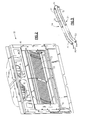
- Fig. 2 is a perspective view of an evaporator coil unit suitable for use in a refrigeration system.
- Fig. 3 is a perspective view of a pair of electrically heated rods.
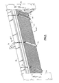
- Fig. 4 is an enlarged view of the evaporator coil and mounting frame of Fig. 2 .
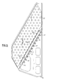
- Fig. 5 is a sectional view of the coil of Fig. 4 taken along line 5-5 .
- Fig. 6 is a schematic diagram of a circuit supplied with a DC voltage controlling the heating rods of the present invention, wherein each conductor is routed through a tube pair.
- Fig. 7 is a schematic diagram of a circuit supplied with an AC voltage controlling the heating rods of the present invention, wherein each conductor is routed through a tube pair.
- Fig. 1 illustrates a transport refrigeration system more particularly known as a trailer refrigeration unit.
- a truck trailer refrigeration unit 500 integrally includes a mounted diesel engine driven generator 300 and the diesel engine 350 in accordance with a system which may use one embodiment of the present invention.
- the truck trailer refrigeration unit 500 has the compressor/drive motor unit 116, 118 and other refrigeration system components. All multi-phase power, single phase power and control system power for the refrigeration unit 500 is provided by the single integrally mounted diesel engine driven generator 300 and associated voltage, current, and frequency controls.
- the internally mounted diesel engine driven generator 300 also provides the necessary higher voltage ac power to the electrically driven compressor/motor unit 116, 118 , electrically driven evaporator fans, the electrically driven condenser fans 123 and a host of high power consumption devices such as heaters.
- FIG. 2 illustrates an evaporator unit 10 which includes a pair of fans 12 and 14 contained within an outer support frame 16 .
- Frame 16 contains an inner mounting frame 18 which contains coil evaporator 20 .
- Coil 20 is made up of a plurality of interconnected spaced metal fins 22 . Separate and apart from the coil are a plurality of interconnected electrically heated rods 24 which are in direct contact with coil fins 22 .
- Metal brackets 34, 36 , and 38 function to hold the coil in place within the evaporator unit.
- each rod 24 is formed as a tube 25 enclosing an electrical conductor 28 , the conductor 28 dissipating heat according to Joule's law (wherein the heat generated is inversely proportional to the resistance of the conductor for a given voltage).
- the conductor 28 is preferably connected at one end via a connector 30 to a suitable source of electrical power, and runs through enclosed tube 25 to an electrical connector 32 , and connects to another tube via an electrical connector 32 , and run through that other tube to another connector 30 that connects the conductor to the electrical power ground, or another electrical phase (not shown).
- each conductor may be connected at one rod end to the electrical power source and at the other rod end to ground or another electrical phase, and thus routing through only a single rod.
- the resistance per length of each conductor is selected according to the chosen heat generation of each road, the length of each conductor, and the current constraints of the voltage source.
- Each tube 25 comprises a material that efficiently conducts heat from the conductor to the contacted fin and at the same time protects the enclosed conductor from deleterious environmental contact.
- Preferred tube material is ceramic, or alternatively metallic wherein the conductor is surrounded by a thin heat conducting dielectric between the metallic tube and the conductor.
- mounting frame 18 contains side mounting brackets 34 and 36 and top mounting bracket 38 which hold the coil in place within the evaporator unit.
- the electrically heated rods are arranged in a parallel array such that they are in direct contact with the coil fins in order to maximize conductive heat flow to the coil, when needed, and provide an integral fit either in or between the fins as desired.
- Fig. 5 which is a sectional view of Fig. 4 , taken along a lines 5-5 , the location and function of the rods with respect to the evaporator fins is shown in greater detail. It can be seen that the array of the rods uniformly covers a major portion of the surface area of the coil, and in the embodiment illustrated, the coils have been cut at 42 to allow the rod to nest in direct contact in a positive secure fit within the coil. This configuration also provides for a even flow of conductive heat from the rods to the coil.
- a DC voltage supplied circuit comprises a voltage source 50 , a switch 52 that opens and closes on demand or alternatively in response to predetermined conditions, a conductor 54 that connects via connectors 30 to each heat dissipating conductor 28 , portrayed as three separate conductors 28a , 28b , and 28c .
- Each conductor 28 runs serially through two rods, electrically connected between each rod by a pair of connectors 32 .
- Each conductor terminates in a connector 30 that is connected to ground.
- an AC voltage supplied circuit comprises a voltage source 51 (portrayed here as three phase AC), a switch 53 that opens and closes on demand or alternatively in response to predetermined conditions, conductors 54a, 54b , and 54c that each connect a different phase of the voltage source and connect via connectors 30 to two of the three separate heat dissipating conductors 28 , portrayed as separate conductors 28a, 28b , and 28c .
- Each conductor 28 runs serially through two rods 24 that are electrically connected between rods by a pair of connectors 32 .
- the present invention may be used with any conventional refrigeration unit.
Landscapes
- Engineering & Computer Science (AREA)
- Chemical & Material Sciences (AREA)
- Combustion & Propulsion (AREA)
- Physics & Mathematics (AREA)
- Mechanical Engineering (AREA)
- Thermal Sciences (AREA)
- General Engineering & Computer Science (AREA)
- Defrosting Systems (AREA)
- General Induction Heating (AREA)
- Devices That Are Associated With Refrigeration Equipment (AREA)
Applications Claiming Priority (2)
| Application Number | Priority Date | Filing Date | Title |
|---|---|---|---|
| US7212098A | 1998-05-04 | 1998-05-04 | |
| US72120 | 1998-05-04 |
Publications (2)
| Publication Number | Publication Date |
|---|---|
| EP0955508A2 true EP0955508A2 (fr) | 1999-11-10 |
| EP0955508A3 EP0955508A3 (fr) | 2001-05-02 |
Family
ID=22105712
Family Applications (1)
| Application Number | Title | Priority Date | Filing Date |
|---|---|---|---|
| EP99302478A Withdrawn EP0955508A3 (fr) | 1998-05-04 | 1999-03-30 | Evaporateur à serpentin avec appareil de chauffage intégré |
Country Status (2)
| Country | Link |
|---|---|
| US (1) | US6298680B1 (fr) |
| EP (1) | EP0955508A3 (fr) |
Cited By (1)
| Publication number | Priority date | Publication date | Assignee | Title |
|---|---|---|---|---|
| WO2007045677A1 (fr) * | 2005-10-20 | 2007-04-26 | I.R.C.A. S.P.A. - Industria Resistenze Corazzate E Affini | Evaporateur a ailettes pour installations frigorifiques pourvu d'un dispositif de degivrage |
Families Citing this family (7)
| Publication number | Priority date | Publication date | Assignee | Title |
|---|---|---|---|---|
| US7845185B2 (en) | 2004-12-29 | 2010-12-07 | York International Corporation | Method and apparatus for dehumidification |
| US7559207B2 (en) | 2005-06-23 | 2009-07-14 | York International Corporation | Method for refrigerant pressure control in refrigeration systems |
| US20090211289A1 (en) * | 2008-02-25 | 2009-08-27 | Carrier Corporation | Electric heater bracket arrangement |
| US20130047638A1 (en) * | 2011-08-31 | 2013-02-28 | General Electric Company | Dryer appliance with accelerated refrigerant cycle |
| CN110939988B (zh) * | 2019-12-13 | 2024-02-27 | 宁波奥克斯电气股份有限公司 | 一种空调器及空气净化控制方法 |
| JP7041369B2 (ja) * | 2020-03-06 | 2022-03-24 | ダイキン工業株式会社 | 輸送用冷凍装置、及び輸送用コンテナ |
| JP7001940B2 (ja) * | 2020-03-06 | 2022-01-20 | ダイキン工業株式会社 | 輸送用冷凍装置、及び輸送用コンテナ |
Family Cites Families (12)
| Publication number | Priority date | Publication date | Assignee | Title |
|---|---|---|---|---|
| US2758150A (en) * | 1952-07-22 | 1956-08-07 | Gen Electric | Electrical connector for refrigerator defrosting means |
| US2705874A (en) * | 1953-05-18 | 1955-04-12 | Binder Eugene | Defroster for refrigeration coils |
| FR1094486A (fr) * | 1953-11-23 | 1955-05-20 | Perfectionnements aux appareils de réfrigération | |
| FR1343691A (fr) * | 1962-10-10 | 1963-11-22 | Bonnet Ets | Perfectionnements aux évaporateurs frigorifiques à dispositif de dégivrage électrique |
| FR1422987A (fr) * | 1964-11-16 | 1966-01-03 | Dispositif de dégivrage électrique pour évaporateurs frigorifiques | |
| US3783635A (en) * | 1972-07-25 | 1974-01-08 | Dunham Bush Inc | Replaceable defrost heater for fin and tube evaporator and spring retaining clip for same |
| US4091637A (en) * | 1976-10-13 | 1978-05-30 | Mcquay-Perfex, Inc. | Electric defrost heater for fin and tube refrigeration heat exchanger |
| US4152900A (en) * | 1978-04-04 | 1979-05-08 | Kramer Trenton Co. | Refrigeration cooling unit with non-uniform heat input for defrost |
| JPS589911B2 (ja) * | 1978-11-29 | 1983-02-23 | 株式会社日立製作所 | 冷凍機用蒸発器 |
| US4492851A (en) * | 1980-12-29 | 1985-01-08 | Brazeway, Inc. | Swap action arrangement mounting an electric defroster heater to a finned refrigeration unit |
| US5013892A (en) * | 1988-08-18 | 1991-05-07 | Anthony Monti | Electrical melting apparatus of confectionery products |
| JPH0651758U (ja) * | 1990-03-13 | 1994-07-15 | 三星電子株式会社 | 冷蔵庫用蒸発器構造 |
-
1999
- 1999-03-30 EP EP99302478A patent/EP0955508A3/fr not_active Withdrawn
-
2000
- 2000-02-11 US US09/502,716 patent/US6298680B1/en not_active Expired - Lifetime
Non-Patent Citations (1)
| Title |
|---|
| "TRANSICOLD DIVISION OPERATION AND SERVICE MANUAL FOR MODELS 69NT40511 AND 69NT40521", CARRIER CORP., pages 1 - 7 |
Cited By (1)
| Publication number | Priority date | Publication date | Assignee | Title |
|---|---|---|---|---|
| WO2007045677A1 (fr) * | 2005-10-20 | 2007-04-26 | I.R.C.A. S.P.A. - Industria Resistenze Corazzate E Affini | Evaporateur a ailettes pour installations frigorifiques pourvu d'un dispositif de degivrage |
Also Published As
| Publication number | Publication date |
|---|---|
| US6298680B1 (en) | 2001-10-09 |
| EP0955508A3 (fr) | 2001-05-02 |
Similar Documents
| Publication | Publication Date | Title |
|---|---|---|
| CN1802876B (zh) | 供暖装置和其安装方法以及包括其的汽车供暖或空调设备 | |
| JP2539571B2 (ja) | 屋外ファン制御装置及びこれを用いた屋外ファン制御方法 | |
| KR100893822B1 (ko) | 가열 미러 | |
| EP1248506B1 (fr) | Radiateur pour des composants sur un circuit imprimé | |
| EP0955508A2 (fr) | Evaporateur à serpentin avec appareil de chauffage intégré | |
| US3868492A (en) | Heated windows in road vehicles | |
| US20230142145A1 (en) | Electrical heating device comprising earthing means | |
| US2429733A (en) | Electric heater of the fan type | |
| US5831242A (en) | Wiper heater insert | |
| EP1004835A3 (fr) | Dispositif pour dégivrer rapidement un compartiment de réfrigérateur, tel que compartiment de congélateur ou analogue | |
| WO2008030231A1 (fr) | Chauffage à impédance pour canaux de drainage d'eau d'échangeur de chaleur | |
| US12434539B2 (en) | Heater device | |
| KR20000007553U (ko) | 공기조화기의 실외기 제상용 전기히터장치 | |
| US1374658A (en) | Electric fan | |
| KR20100000610U (ko) | 자동차용 프리 히터 | |
| JP2002198164A (ja) | 誘導加熱調理器 | |
| US1998916A (en) | Electric heating device | |
| US2178336A (en) | Refrigerator defroster | |
| US5173843A (en) | Fan control and diode interlock for electric heaters | |
| CN215723523U (zh) | 暖风机 | |
| RU2852790C1 (ru) | Безынерционный отопитель электрического транспорта | |
| EP3296660A1 (fr) | Chauffage électrique | |
| KR100213618B1 (ko) | 냉장고 제상용 코드히터장치 | |
| KR200191144Y1 (ko) | 열교환기 | |
| KR19990026172A (ko) | 공기조화기의 히터내장형 증발기 |
Legal Events
| Date | Code | Title | Description |
|---|---|---|---|
| PUAI | Public reference made under article 153(3) epc to a published international application that has entered the european phase |
Free format text: ORIGINAL CODE: 0009012 |
|
| AK | Designated contracting states |
Kind code of ref document: A2 Designated state(s): AT DE ES FR GB IT NL |
|
| AX | Request for extension of the european patent |
Free format text: AL;LT;LV;MK;RO;SI |
|
| PUAL | Search report despatched |
Free format text: ORIGINAL CODE: 0009013 |
|
| AK | Designated contracting states |
Kind code of ref document: A3 Designated state(s): AT BE CH CY DE DK ES FI FR GB GR IE IT LI LU MC NL PT SE |
|
| AX | Request for extension of the european patent |
Free format text: AL;LT;LV;MK;RO;SI |
|
| RIC1 | Information provided on ipc code assigned before grant |
Free format text: 7F 25D 21/08 A, 7H 05B 3/44 B |
|
| 17P | Request for examination filed |
Effective date: 20010518 |
|
| AKX | Designation fees paid |
Free format text: AT DE ES FR GB IT NL |
|
| 17Q | First examination report despatched |
Effective date: 20030709 |
|
| STAA | Information on the status of an ep patent application or granted ep patent |
Free format text: STATUS: THE APPLICATION IS DEEMED TO BE WITHDRAWN |
|
| 18D | Application deemed to be withdrawn |
Effective date: 20040120 |