EP0955548A1 - Gerät zum Detektion von elektromagnetischen Wellen - Google Patents
Gerät zum Detektion von elektromagnetischen Wellen Download PDFInfo
- Publication number
- EP0955548A1 EP0955548A1 EP98303593A EP98303593A EP0955548A1 EP 0955548 A1 EP0955548 A1 EP 0955548A1 EP 98303593 A EP98303593 A EP 98303593A EP 98303593 A EP98303593 A EP 98303593A EP 0955548 A1 EP0955548 A1 EP 0955548A1
- Authority
- EP
- European Patent Office
- Prior art keywords
- electromagnetic waves
- diode
- rectifire
- detecting electromagnetic
- conductor
- Prior art date
- Legal status (The legal status is an assumption and is not a legal conclusion. Google has not performed a legal analysis and makes no representation as to the accuracy of the status listed.)
- Withdrawn
Links
- 239000004020 conductor Substances 0.000 claims abstract description 20
- 239000003990 capacitor Substances 0.000 claims description 5
- 238000001514 detection method Methods 0.000 claims description 5
- 238000009499 grossing Methods 0.000 claims description 4
- 238000010586 diagram Methods 0.000 description 14
- 230000000694 effects Effects 0.000 description 6
- 230000005284 excitation Effects 0.000 description 2
- 230000001149 cognitive effect Effects 0.000 description 1
- 239000003086 colorant Substances 0.000 description 1
- 230000005669 field effect Effects 0.000 description 1
- 238000004519 manufacturing process Methods 0.000 description 1
- 239000000463 material Substances 0.000 description 1
- 230000035945 sensitivity Effects 0.000 description 1
Images










Classifications
-
- G—PHYSICS
- G01—MEASURING; TESTING
- G01R—MEASURING ELECTRIC VARIABLES; MEASURING MAGNETIC VARIABLES
- G01R29/00—Arrangements for measuring or indicating electric quantities not covered by groups G01R19/00 - G01R27/00
- G01R29/08—Measuring electromagnetic field characteristics
- G01R29/0864—Measuring electromagnetic field characteristics characterised by constructional or functional features
- G01R29/0871—Complete apparatus or systems; circuits, e.g. receivers or amplifiers
-
- H—ELECTRICITY
- H04—ELECTRIC COMMUNICATION TECHNIQUE
- H04B—TRANSMISSION
- H04B1/00—Details of transmission systems, not covered by a single one of groups H04B3/00 - H04B13/00; Details of transmission systems not characterised by the medium used for transmission
- H04B1/38—Transceivers, i.e. devices in which transmitter and receiver form a structural unit and in which at least one part is used for functions of transmitting and receiving
- H04B1/3827—Portable transceivers
- H04B1/3833—Hand-held transceivers
- H04B1/3838—Arrangements for reducing RF exposure to the user, e.g. by changing the shape of the transceiver while in use
Definitions
- the present invention relates to a device for detecting electromagnetic waves capable of the detecting it that is used for a portable telephone or which dose harm to human body.
- Conventional indicator for a portable telephone as a detector which is able to inform a user visually when the portable telephone comes to the calling-up and message received conditions or a calling condition, is composed of first and second rectifire diodes connected to a top end of the portable telephone with alternating ends thereof as to the opposite direction; first and second conductive pins connected to the other ends of the rectifire diodes with each of other ends thereof; and a luminous element connected between the first and second conductive pins.
- the conventional indicator for portable telephone includes two rectifire diodes such that its structure is complex, and it costs too much. In addition, it is possible to use as the indicator only when the indicator is provided to the top end of the antenna of the portable telephone.
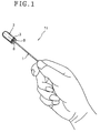
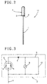
- Figs. 1 to 3 illustrate a device for detecting electromagnetic waves 11 of a first embodiment of the present invention wherein the numeral 1 is a conductor formed in the shape of a rod and able to be held at a back end portion thereof by hand, and the conductor 1 is used to same materials as antenna used before.
- the numeral 1 is a conductor formed in the shape of a rod and able to be held at a back end portion thereof by hand, and the conductor 1 is used to same materials as antenna used before.
- the numeral 2 is an indicator of electromagnetic waves provided to a top end portion of the conductor 1 and further comprises a case body 3 fixedly provided to the top end portion of the conductor 1; a LC-resonance circuit 6 set up as to connect with the conductor into the case body 3 including a capacitor 4 and a coil 5, arranged parallel into the circuit 6 in order to tune the desirable frequency; a detecting circuit of electromagnetic waves X further includes a rectifire diode 7, a DC (direct current) indicator 9 as indicating device, and a smoothing capacitor 10.
- the rectifire diode 7 is installed within the case body 3, both ends thereof are connected to both ends of the resonance circuit 6, and the rectifire diode 7 can convert a high frequency alternating current which generates by the resonance circuit 6 to direct current.
- the DC indicator 9 is connected in series to the rectifire diode 7, and has an indicator section 8 which is provided within the case body 3 as to be able to check the meter movement from outside and can moves corresponding to the strength of a DC electric current flows from the rectifire diode 7.
- the smoothing condensor 10 is installed within the case body 3 and connected in parallel to the indicator 9 as required.
- the excitation potential is converted a direct current by the rectifire diode 7 and flows to the indicator 9 as indicating device, so that the excitation potential genarates at the both ends of the coil 5 of the resonance circuit 6 in proportion to the strength of electromagnetic waves at the sending place, in order that there is the sending place of electric wave in that direction.
- the user can detect electromagnetic waves and find the sending place because the indicator section 8 moves visually by the strength of a DC electric current which is flown from the rectifire diode 7.
- the movement range of the indicator section 8 of the DC indicator 9 as indicating device changes to a slow-moving in order that the smoothing capacitor 10 is installed thereinto. Therefore, the user can confirm the detecting electromagnetic waves easily.
- Figs. 4 and 5 illustrate a second embodiment of the present invention which is distinguished from the first embodiment by the fact that an amplifier 12 is interposed between the rectifire diode 7 and the DC indicator 9 into the detecting circuit X and further composed of a wide-use transistor, field effect transistor (FET), and integrated circuit (IC).
- FET field effect transistor
- IC integrated circuit
- Figs. 6 and 7 illustrate a third embodiment of the present invention which is distinguished from the first embodiment by the fact that a detector 2B has a coil 5, instead of the LC-resonance circuit, which is able to be made a potential difference bring about therethrough.
- a device for detecting electroamagnetic waves 11B is formed in this way according to the third embodiment and provides the same effects as the first embodiment.
- Figs. 8 and 9 illustrate a fourth embodiment of the present invention which is distinguished from the second embodiment by the fact that a detector 2B has a coil 5, instead of the LC-resonance circuit, which is able to be made a potential difference bring about therethrough.
- a device for detecting electromagnetic waves 11C is formed in this way according to the fourth embodiment and provides the same effects as the second embodiment.
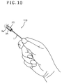
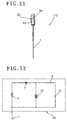
- Figs. 10 to 12 illustrate a fifth embodiment of the present invention which is distinguished from the third embodiment by the fact that a detector 2D has a light emitting diode 13 instead of the DC indicator of the detecting circuit X of electromagnetic waves.
- the coil 5 has higher level potential in full at the both ends thereof, the wave detecting can be done efficiently such that a user can recognize the lighting of the light emitting diode 13 through a transparent body 3aof the upper part of the case body 3A, into the strong magnetic field as taking large amounts of current over the spent current of the light emitting diode 13.
- Figs. 13 and 14 illustrate a sixth embodiment of the present invention which is distinguished from the fourth embodiment by the fact that a detector 2E has a light emitting diode 13, as an inducting device, of the detecting circuit X of electromagnetic waves.
- the wave detecting can be done efficiently, so that the light emitting diode 13 is lighted directly, into strong magnetic field as taking large amounts of current over the spent current of the light emitting diode 13.
- Figs. 15 and 16 illustrate a seventh embodiment of the present invention which is distinguished from the sixth embodiment by the fact that an attachment 16 is provided at a back end thereof and can be mounted to an antenna attachment 15 with a portable telephone 14.
- a device for detecting electromagnetic waves 11E can be used as the antenna of the portable telephone 14.
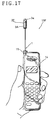
- Figs. 17 to 19 illustrate an eighth embodiment of the present invention which is distinguished from the fifth embodiment by the fact that the wave detecting circuit X includes two wave detectors 2D, 2D connected in series as to be able to light one of light emitting diodes 13, 13A or both of them corresponding to the strength of waves in the strong magnetic field.
- a device for detecting electromagnetic waves 11G formed in this way according to the eighth embodiment can be easily detected waves and confirm of the strength of waves, so that the light emitting diodes 13, 13A can be lighted at transparent bodies 3a, 3b of upper and lower parts of the case body 3A, corresponding to the strength in the strong magnetic field.
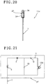
- Figs. 20 and 21 illustrate a ninth embodiment of the present invention which is distinguished from the sixth embodiment by the fact that a wave detector 2F includes an automatic flashing type light emitting diode 13B as the indicating device, which is on the market, into the wave detecting circuit X.
- a device for detecting electromagnetic waves 11H formed in this way according to the ninth embodiment can be improved a cognitive power visually in comparison with the use of ordinary diode.
- Figs. 22 and 23 illustrate a tenth embodiment of the present invention which is distinguished from the first embodiment by the fact that a wave detector 2G includes a piezoelectric buzzer 17 that is mounted as to be sounded from a porous part 18 formed at a case body 3B, instead of the DC indicator of the wave detecting circuit X.
- a device for detecting electromagnetic waves 11I formed in this way according to the tenth embodiment will provide the same effects as the first embodiment.
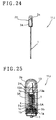
- Figs. 24 to 27 illustrate an eleventh embodiment of the present invention which is distinguished from the fifth embodiment by the fact that a wave detector 2H has such a structure that one end of a coil 5A is soldered directly at one of a terminal 13a of the light emitting diode 13, the other terminal 13b of the light emitting diode 13 is soldered directly at one of a terminal 7a of the rectifire diode 7, and the other terminal 7b of the rectifire diode 7 is soldered nearly at the other end portion of the coil 5A, so as to prevent to damage the connection between the light emitting diode 13 and the rectifire diode 7 by the elasticity of the coil 5A.
- a device for detecting electromagnetic waves 11J formed in this way according to the eleventh embodiment will provide the same effects as the fifth embodiment, it can be prevented efficiently the troubles including broken wire during use.
- the other end of the coil 5A is fixedly inserted into a coil support 1c, the coil support 1c having a coil ditch support 1b at outer circumferential thereof, furthermore, a screw head 1a formed at a top end of the conductor 1 screwed with a groove 3b at a lower end allowance of the case body 3A.
- Figs. 28 to 31 illustrate a twelfth embodiment of the present invention which is distinguished from the eleventh embodiment by the fact that the other terminal 7b of the rectifire diode 7 is bent in an arc-shaped as to have an elasticity of coil 5A, the top end portion of the terminal 7b is soldered at the coil support 1c.
- a device for detecting electromagnetic waves 11K formed in this way according to the twelfth embodiment will provide the same effects as the eleventh embodiment.
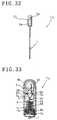
- Figs. 32 to 34 illustrate a thirteenth embodiment of the present invention which is distinguished from the eleventh embodiment by the fact that a wave detector 2J has a pair of rectifire diodes 7, 7A is connected alternatively in the opposite direction at top end of the coil 5A, one end of coupled terminal 7b being soldered directly, the other terminals 7a, 7a thereof being soldered at terminals 13a, 13b of the light emitting diode 13.
- a device for detecting electromagnetic waves 11L formed in this way according to the thirteenth embodiment will provide the same effects as to the eleventh embodiment.
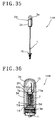
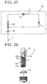
- Figs. 35 to 38 illustrate an fourteenth embodiment of the present invention which is distinguished from the eleventh embodiment by the fact that a conductor 1 has an attachment 16 at a rear end thereof, the attachment 16 providing to an antenna attachment of the portable telephone, in addition, a capacitive resister 18 is interposed between the conductor 1 and the coil 5A.
- a device for detecting electromagnetic waves 11M formed in this way according to the fourteenth embodiment can be used as the antenna for the portable telephone.
Landscapes
- Physics & Mathematics (AREA)
- Electromagnetism (AREA)
- General Physics & Mathematics (AREA)
- Engineering & Computer Science (AREA)
- Computer Networks & Wireless Communication (AREA)
- Signal Processing (AREA)
- Measurement Of Current Or Voltage (AREA)
- Mobile Radio Communication Systems (AREA)
Priority Applications (2)
| Application Number | Priority Date | Filing Date | Title |
|---|---|---|---|
| US09/073,176 US6064190A (en) | 1998-05-05 | 1998-05-05 | Hand held electromagnetic field detector |
| EP98303593A EP0955548A1 (de) | 1998-05-05 | 1998-05-07 | Gerät zum Detektion von elektromagnetischen Wellen |
Applications Claiming Priority (2)
| Application Number | Priority Date | Filing Date | Title |
|---|---|---|---|
| US09/073,176 US6064190A (en) | 1998-05-05 | 1998-05-05 | Hand held electromagnetic field detector |
| EP98303593A EP0955548A1 (de) | 1998-05-05 | 1998-05-07 | Gerät zum Detektion von elektromagnetischen Wellen |
Publications (1)
| Publication Number | Publication Date |
|---|---|
| EP0955548A1 true EP0955548A1 (de) | 1999-11-10 |
Family
ID=26151249
Family Applications (1)
| Application Number | Title | Priority Date | Filing Date |
|---|---|---|---|
| EP98303593A Withdrawn EP0955548A1 (de) | 1998-05-05 | 1998-05-07 | Gerät zum Detektion von elektromagnetischen Wellen |
Country Status (2)
| Country | Link |
|---|---|
| US (1) | US6064190A (de) |
| EP (1) | EP0955548A1 (de) |
Cited By (1)
| Publication number | Priority date | Publication date | Assignee | Title |
|---|---|---|---|---|
| WO2015009292A1 (en) * | 2013-07-17 | 2015-01-22 | Magneticomm, Inc. | Mobile electric communications device transmission monitoring device |
Families Citing this family (3)
| Publication number | Priority date | Publication date | Assignee | Title |
|---|---|---|---|---|
| US6232881B1 (en) * | 1998-05-05 | 2001-05-15 | Yoshimitu Suda | Hand held electromagnetic field detector |
| US20090267846A1 (en) * | 2008-04-28 | 2009-10-29 | Johnson Michael P | Electromagnetic Field Power Density Monitoring System and Methods |
| US9517421B1 (en) * | 2011-12-08 | 2016-12-13 | Maureen Mae | Device for fanciful detection of ghosts |
Citations (2)
| Publication number | Priority date | Publication date | Assignee | Title |
|---|---|---|---|---|
| JPH02104031A (ja) * | 1988-10-12 | 1990-04-17 | Nec Corp | 携帯用通信装置 |
| DE4428882A1 (de) * | 1994-08-17 | 1996-02-22 | Gerhard Dr Sc Nat Zeschke | Elektrosmog-Detektor |
Family Cites Families (3)
| Publication number | Priority date | Publication date | Assignee | Title |
|---|---|---|---|---|
| US4431965A (en) * | 1981-04-16 | 1984-02-14 | The Narda Microwave Corporation | Microwave radiation monitor |
| US4424483A (en) * | 1981-04-16 | 1984-01-03 | The Narda Microwave Corporation | Microwave radiation monitor |
| US4692685A (en) * | 1984-03-14 | 1987-09-08 | Blaze Kevin L | Electrical measuring apparatus, and methods for determining the condition or identity of biological material |
-
1998
- 1998-05-05 US US09/073,176 patent/US6064190A/en not_active Expired - Fee Related
- 1998-05-07 EP EP98303593A patent/EP0955548A1/de not_active Withdrawn
Patent Citations (2)
| Publication number | Priority date | Publication date | Assignee | Title |
|---|---|---|---|---|
| JPH02104031A (ja) * | 1988-10-12 | 1990-04-17 | Nec Corp | 携帯用通信装置 |
| DE4428882A1 (de) * | 1994-08-17 | 1996-02-22 | Gerhard Dr Sc Nat Zeschke | Elektrosmog-Detektor |
Non-Patent Citations (2)
| Title |
|---|
| KLEINSCHMIDT: "The ARRL Handbook for the Radio Amateur", 1990, AMERICAN RADIO RELAY LEAGUE, NEWINGTON , CT , US, XP002079976 * |
| PATENT ABSTRACTS OF JAPAN vol. 014, no. 316 (E - 0949) 6 July 1990 (1990-07-06) * |
Cited By (1)
| Publication number | Priority date | Publication date | Assignee | Title |
|---|---|---|---|---|
| WO2015009292A1 (en) * | 2013-07-17 | 2015-01-22 | Magneticomm, Inc. | Mobile electric communications device transmission monitoring device |
Also Published As
| Publication number | Publication date |
|---|---|
| US6064190A (en) | 2000-05-16 |
Similar Documents
| Publication | Publication Date | Title |
|---|---|---|
| US5103165A (en) | Insulated, hand-held non-contacting voltage detection probe | |
| KR102182669B1 (ko) | 벽에 설치 가능한 무선전력 전송장치 | |
| ES2080036T1 (es) | Adaptador de localizador de conductores para marcadores electronicos. | |
| EP3225439A1 (de) | Steckbarer luftqualitätsdetektor, steuerungsverfahren und steuerungsschaltung | |
| US6232881B1 (en) | Hand held electromagnetic field detector | |
| EP0955548A1 (de) | Gerät zum Detektion von elektromagnetischen Wellen | |
| US6297778B1 (en) | Apparatus and method for ensuring proper antenna position | |
| HK1022741A (en) | Device for detecting electromagnetic waves | |
| CN207379582U (zh) | 车辆涉水检测装置及车辆 | |
| US4999820A (en) | Hour meter activated by magnetic influence | |
| CN211236003U (zh) | 一种全回路直流验电器 | |
| US6265981B1 (en) | Apparatus for detecting operation of an electric fence and fence charger | |
| US7130666B2 (en) | Cell phone charger with incoming call indicator | |
| JPH10197581A (ja) | 電波の検出装置 | |
| CN211431093U (zh) | 一种磁吸充电结构 | |
| JP3066889U (ja) | 通信機器用発光装置 | |
| JP2001217620A (ja) | 電磁波検知器 | |
| KR20210068349A (ko) | 벽에 설치 가능한 무선전력 전송장치 | |
| CN2556652Y (zh) | 万能测电笔 | |
| JP3070726U (ja) | 電磁波検知器 | |
| CN217640350U (zh) | 一种基于振动信号的远程报警装置 | |
| JP3071278U (ja) | 携帯型通信機用アンテナ装置 | |
| CN220022776U (zh) | 多线输出型接近开关 | |
| CN211824636U (zh) | 路面积水检测设备 | |
| US6531878B1 (en) | Direct current voltage detection stick |
Legal Events
| Date | Code | Title | Description |
|---|---|---|---|
| PUAI | Public reference made under article 153(3) epc to a published international application that has entered the european phase |
Free format text: ORIGINAL CODE: 0009012 |
|
| AK | Designated contracting states |
Kind code of ref document: A1 Designated state(s): AT BE CH DE DK ES FI FR GB GR IE IT LI LU MC NL PT SE |
|
| AX | Request for extension of the european patent |
Free format text: AL;LT;LV;MK;RO;SI |
|
| 17P | Request for examination filed |
Effective date: 19991222 |
|
| AKX | Designation fees paid |
Free format text: AT BE CH DE DK ES FI FR GB GR IE IT LI LU MC NL PT SE |
|
| 17Q | First examination report despatched |
Effective date: 20010731 |
|
| GRAH | Despatch of communication of intention to grant a patent |
Free format text: ORIGINAL CODE: EPIDOS IGRA |
|
| GRAH | Despatch of communication of intention to grant a patent |
Free format text: ORIGINAL CODE: EPIDOS IGRA |
|
| STAA | Information on the status of an ep patent application or granted ep patent |
Free format text: STATUS: THE APPLICATION IS DEEMED TO BE WITHDRAWN |
|
| 18D | Application deemed to be withdrawn |
Effective date: 20021203 |
|
| REG | Reference to a national code |
Ref country code: HK Ref legal event code: WD Ref document number: 1022741 Country of ref document: HK |