EP0955555A2 - Tieftemperaturkühler mit supraleitendem Mantel für ein bildgebendes Magnetresonanzgerät mit Helium-Wiederverflüssigung - Google Patents
Tieftemperaturkühler mit supraleitendem Mantel für ein bildgebendes Magnetresonanzgerät mit Helium-Wiederverflüssigung Download PDFInfo
- Publication number
- EP0955555A2 EP0955555A2 EP99303501A EP99303501A EP0955555A2 EP 0955555 A2 EP0955555 A2 EP 0955555A2 EP 99303501 A EP99303501 A EP 99303501A EP 99303501 A EP99303501 A EP 99303501A EP 0955555 A2 EP0955555 A2 EP 0955555A2
- Authority
- EP
- European Patent Office
- Prior art keywords
- superconducting
- cryocooler
- sleeve
- superconducting magnet
- magnet
- Prior art date
- Legal status (The legal status is an assumption and is not a legal conclusion. Google has not performed a legal analysis and makes no representation as to the accuracy of the status listed.)
- Granted
Links
Images
Classifications
-
- G—PHYSICS
- G01—MEASURING; TESTING
- G01R—MEASURING ELECTRIC VARIABLES; MEASURING MAGNETIC VARIABLES
- G01R33/00—Arrangements or instruments for measuring magnetic variables
- G01R33/20—Arrangements or instruments for measuring magnetic variables involving magnetic resonance
- G01R33/28—Details of apparatus provided for in groups G01R33/44 - G01R33/64
- G01R33/38—Systems for generation, homogenisation or stabilisation of the main or gradient magnetic field
- G01R33/381—Systems for generation, homogenisation or stabilisation of the main or gradient magnetic field using electromagnets
- G01R33/3815—Systems for generation, homogenisation or stabilisation of the main or gradient magnetic field using electromagnets with superconducting coils, e.g. power supply therefor
Definitions
- This invention relates to a mechanical cryocooler cryogen recondensing system for a superconducting magnet.
- a magnet coil can be made superconducting by placing it in an extremely cold environment, such as by enclosing it in a cryostat or pressure vessel and reducing its temperature to superconducting levels such as 4-10° Kelvin.
- the extreme cold reduces the resistance of the magnet coil to negligible levels, such that when a power source is initially connected to the coil for a period of time to introduce a current flow through the coil, the current will continue to flow through the coil due to the negligible coil resistance at superconducting temperatures even after power is removed, thereby maintaining a strong, steady magnetic field.
- Superconducting magnets find wide application, for example, in the field of magnetic resonance imaging (hereinafter "MRI").
- the main superconducting magnet coils are enclosed in a cylindrically shaped pressure vessel which is contained within an evacuated vessel and forms an imaging bore in the central region.
- the main magnet coils develop a strong magnetic field in the imaging bore which must be very homogenous and temporally constant for accurate imaging.
- cryocooler such as the Gifford-McMahon type
- One type of cryocooler that has desirable cooling capacity uses.
- rare earth materials as the displacement material in the moving piston of the compressor for the second or cold stage of a two stage cryocooler.
- the rare earth materials such as Er 3 Ni, HoCu 2 , or ErNiCo produces relatively high heat capacity in the superconducting temperature range of 4-10° K due to magnetic transitions to enable low temperature operation.
- cryocoolers utilizing ferromagnetic transition rare earth materials in MRI applications can cause significant distortions and perturbations of the magnetic field in the MRI imaging volume.
- the rare earth material in the moving displacer is believed to act as a moving magnet of variable field strength when it becomes magnetized by the local field of a typical superconductive magnet, in turn causing magnetic field fluctuations in the imaging volume of the superconductive magnet, which creates unacceptable distortions in the images rendered.
- the time varying magnetic fields generated by the moving rare earth displacer can also induce eddy currents in various metallic structures of the main magnet assembly and in the main magnet coils.
- the presence of eddy currents is most undesirable in MRI applications of rare earth cryocoolers since such eddy currents will generate heat due to the finite electrical resistance of the structures and coils involved. This is the so called AC heating effect of eddy currents which is an additional thermal burden in providing adequate cooling in systems utilizing cryocoolers.
- a mechanical displacement rare-earth cryocooler provides cooling for condensing and recycling boiled helium in superconducting recondensing operation of an MRI magnet.
- a magnetic superconducting shielding sleeve surrounds a portion of the rare earth displacer in the terminal portion of the cryocooler housing. The shielding sleeve is in close proximity to the cold head of the cryocooler, is magnetically coupled to the magnetic fields generated by movement of the rare-earth displacer, and surrounds 90-270 degrees of the cold head to which it is thermally coupled.
- the superconducting sleeve shield includes layers of copper and NbTi alloy and is interposed between the cold head and the imaging region in the bore of the magnet.
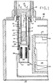
- FIG. 1 is a simplified cross-sectional view of a rare earth cryocooler and cryostat penetration area for a zero boiloffMRI cryogen recondensing superconducting magnet in accordance with this invention.
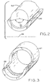
- FIG. 2 shows details of the superconducting sleeve of FIG. 1 in a contacting configuration with the cryocooler cold head.
- FIG. 3 is an enlarged perspective view of the superconducting sleeve shown in FIGs. 1 and 2.
- two-stage cryocooler 10 includes a housing 8 forming an internal cylindrical bore 12 in which second stage displacer 14 driven by drive motor 15 through mechanical drive 21 (shown in simplified form) reciprocates as indicated by arrow 9.
- Second stage displacer 14 is a rare-earth material such as ErNiCo utilized in cryocoolers such as those sold by Sumitomo Heavy Industries under their coldhead model designation RDK-408.
- Cryocooler 10 is inserted into sealed and evacuated cavity 32 within evacuated vessel 5 formed by sleeve walls 2 and 4 and intermediate collar 3 within MRI superconducting magnet 30.
- the rare-earth materials of second stage displacer 14 have relatively high heat capacity in the 4-10 K range due to magnetic transitions enabling cryocooler 10 to reduce the temperature of cryogen recondensing apparatus 33 to which it is thermally connected to superconducting temperatures.
- the thermal connection is made through separable thermal joint 50 which includes copper thermal member or cold head 52 on cryocooler 10 and copper thermal member 54 within MRI magnet 30 and forming the bottom surface of cavity 32. This enables the removal and replacement of cryocooler 10 without breaking the vacuum within vacuum vessel 5 of superconducting magnet 30 or discontinuing superconducting operation of the magnet.
- the recondensing and recycling of the boiled cryogen results from the boiling of liquid helium from helium cryogen reservoir 36 within pressurized vessel 35 to cool main magnet coils such as 34 to superconducting temperatures.
- the helium gas is passed between parallel recondensing surfaces 58 in recondenser 33 to be recondensed to liquid helium which collects at bottom 16 of the recondenser and flows by gravity via return line 60 to be returned as liquid helium to the liquid helium reservoir 36 within pressurized vessel 35 of MRI superconducting magnet 30.
- the result is a zero boiloff(ZBO) closed loop helium boiling and recondensing system without the need to replenish the boiled helium by periodic additions from an external source of liquid helium.
- the cooled recondensing surfaces 58 are formed by slots in thermal member 54, or plates in recondenser 33, between which the helium gas flows to be recondensed.
- Displacer 14 is driven at a constant frequency and amplitude along axis 9 by the drive motor 15 supplied by electrical power at terminals 19. It is believed that the rare-earth material in the moving displacer acts as a moving magnet of varying strength (magnetic moment) generating strong varying magnetic fields which can interact with the magnetic fields produced by main magnet coils 34 and associated coils (not shown) of MRI superconducting magnet 30 causing magnetic field fluctuations in the imaging region or bore 40 of the superconducting magnet.
- the magnetic field generated by the moving second stage displacer 14 must accordingly, be minimized and/or prevented from interfering with the magnetic homogeneity within central imaging bore or volume 40 in order to avoid distortions in the imaging quality if the rare earth cryocooler 10 is to be suitable and practical for use in MRI imaging.
- Superconducting sleeve 20 is fitted around cavity 32 in the region surrounding second stage displacer 14 of the second or cold stage of cryocooler 10.
- Superconductive sleeve 20 may be of a lead bismuth alloy (60 parts lead and 40 parts, by weight, bismuth) which has proven to exhibit desirable limiting current characteristics in the event of a quenching, or discontinuing superconducting operation, of superconducting magnet 30.
- Such a shield can provide shielding that reduce AC magnetic fields by an order of 100.
- superconducting shield 20 is attached to and contacts coldhead 52 at one end to surround the rare earth material displacer 14 (see FIG. 1).
- Superconducting shield 20 in FIG. 1 does not physically contact cold head 52 but does closely surround the cold head in thermal contact with the cold head.
- Superconducting shield 20 is partial cylinder surrounding a portion of cold head 52 as indicated by angle 62, which angle may be approximately 270° and vary from approximately 90°-270° around the circumference of the cold head.
- Superconducting shield 20 is thus positioned on or around cold head 52 and interposed between the cryocooler and axis 64 of bore 40 of superconducting magnet 30, that is between cryocooler 10 and the MRI imaging region within bore 40 to shield the magnetic field in the imaging region from magnetic perturbations generated by rare earth cryocooler 10.
- superconducting shield 20 may include a cylindrical collar portion 27 at the end closest to motor 15. Collar portion 27 fully encircles cryocooler 12 and assists in securing the collar to the cryocooler.
- superconducting or superconductive shield 20 is not a continuous cylindrical superconducting sheet, it nevertheless can contain and maintain a large number of superconducting loops to enable continuous generation of the magnetic fields induced to shield main magnet field coils 34 of MRI superconducting magnet 30 from the magnetic field perturbations of cryocooler 10 and prevent them from adversely affecting the magnetic field within imaging volume 40 (see FIG. 1) of the MRI magnet bore.
- This enables main magnet coils 34 and associated coils (not shown) to provide the desired and necessary field homogeneity and stability without undue magnetic interference from cryocooler 10 rare earth second stage displacer 14.
- the magnetic fields induced in shield 20 oppose and thus limit eddy current flows and heating in the structural members of superconducting magnet 30
- Sleeve 20 in the embodiment of FIG. 2 fits snugly around the cylindrical outer surface of housing 52 of cryocooler 10 using thermal grease which is vacuum grease including copper powder or solder to provide good thermal contact and magnetic coupling with second stage displacer 14 of the cryocooler. Sleeve 20 is then soldered in place. Sleeve 20 is 6.25 inches long, 2 inches in diameter and 0.13 inches thick for one MRI superconducting magnet.
- cryocooler 10 including its attached drive motor 15 and associated components along with superconducting shield 20 has proven to be difficult for a single person to readily accomplish in the field.
- the assembly can weigh up to 40 pounds in magnets 30 in which superconducting sleeve 20 is fit around and retained on cold head cryocooler 10 for removal with the cryocooler. As a result, reduction in weight of sleeve 20 when removing the sleeve along with cryocooler 10 can be significant and highly desirable.
- the full cylindrical superconducting sleeve 20 can cost as much as $2,000, such that the partial sleeve can also significantly reduce costs of the sleeve and MRI 30.
- superconducting sleeve 20 closely surrounding the cold head of cryocooler 10 is less of a cryogenic heat load on the cryocooler than a full cylindrical sheild would be. This is of particular significance because mechanical cryocoolers are often operating at or near their full capacity and any reduction in thermal loading assists in enabling effective and reliable superconducting operation.
Landscapes
- Physics & Mathematics (AREA)
- Electromagnetism (AREA)
- Condensed Matter Physics & Semiconductors (AREA)
- General Physics & Mathematics (AREA)
- Magnetic Resonance Imaging Apparatus (AREA)
- Details Of Measuring And Other Instruments (AREA)
- Shielding Devices Or Components To Electric Or Magnetic Fields (AREA)
Applications Claiming Priority (2)
| Application Number | Priority Date | Filing Date | Title |
|---|---|---|---|
| US09/074,332 US6029458A (en) | 1998-05-07 | 1998-05-07 | Helium recondensing magnetic resonance imager superconducting shield |
| US74332 | 1998-05-07 |
Publications (3)
| Publication Number | Publication Date |
|---|---|
| EP0955555A2 true EP0955555A2 (de) | 1999-11-10 |
| EP0955555A3 EP0955555A3 (de) | 2001-06-20 |
| EP0955555B1 EP0955555B1 (de) | 2006-03-22 |
Family
ID=22118995
Family Applications (1)
| Application Number | Title | Priority Date | Filing Date |
|---|---|---|---|
| EP99303501A Expired - Lifetime EP0955555B1 (de) | 1998-05-07 | 1999-05-05 | Tieftemperaturkühler mit supraleitendem Mantel für ein bildgebendes Magnetresonanzgerät mit Helium-Wiederverflüssigung |
Country Status (4)
| Country | Link |
|---|---|
| US (1) | US6029458A (de) |
| EP (1) | EP0955555B1 (de) |
| JP (1) | JP4412760B2 (de) |
| DE (1) | DE69930472T2 (de) |
Cited By (7)
| Publication number | Priority date | Publication date | Assignee | Title |
|---|---|---|---|---|
| EP1102020A3 (de) * | 1999-11-16 | 2002-08-21 | General Electric Company | Positioniermechanismus eines Tieftemperaturkühlers für Bilderzeugung durch magnetische Resonanz |
| GB2389647A (en) * | 2002-06-14 | 2003-12-17 | Bruker Biospin Gmbh | Recondensing helium cryostat |
| EP1736723A3 (de) * | 2005-06-23 | 2010-01-13 | Bruker BioSpin AG | Kryostatanordnung mit Kryokühler |
| EP1923714A3 (de) * | 2006-11-20 | 2010-09-01 | Hitachi, Ltd. | Supraleitender Magnet mit abgeschirmter Kühlanlage |
| US7924011B2 (en) | 2005-06-28 | 2011-04-12 | Koninklijke Philips Electronics N.V. | Ferromagnetic shield for magnetic resonance imaging |
| US10809330B2 (en) | 2016-03-09 | 2020-10-20 | Synaptive Medical (Barbados) Inc. | Reducing magnetic field instabilities caused by oscillations of a mechanical cryo-cooler in magnetic resonance systems |
| US11474176B2 (en) | 2019-09-03 | 2022-10-18 | Synaptive Medical Inc. | Method and system for reducing magnetic field instabilities in a magnetic resonance system |
Families Citing this family (16)
| Publication number | Priority date | Publication date | Assignee | Title |
|---|---|---|---|---|
| DE10033410C1 (de) * | 2000-07-08 | 2002-05-23 | Bruker Biospin Gmbh | Kreislaufkryostat |
| US6438966B1 (en) * | 2001-06-13 | 2002-08-27 | Applied Superconetics, Inc. | Cryocooler interface sleeve |
| JP4520676B2 (ja) * | 2001-08-31 | 2010-08-11 | アイシン精機株式会社 | 冷却装置 |
| JP4040626B2 (ja) * | 2002-12-16 | 2008-01-30 | 住友重機械工業株式会社 | 冷凍機の取付方法及び装置 |
| US6807812B2 (en) * | 2003-03-19 | 2004-10-26 | Ge Medical Systems Global Technology Company, Llc | Pulse tube cryocooler system for magnetic resonance superconducting magnets |
| US7464558B2 (en) * | 2003-11-19 | 2008-12-16 | General Electric Company | Low eddy current cryogen circuit for superconducting magnets |
| DE102004023072B4 (de) | 2004-05-11 | 2008-08-14 | Bruker Biospin Ag | Magnetsystem mit abgeschirmtem Regeneratormaterial und Verfahren zum Betrieb des Magnetsystems |
| DE102004023073B3 (de) * | 2004-05-11 | 2006-01-05 | Bruker Biospin Gmbh | Magnetsystem mit abgeschirmten Regeneratorgehäuse und Verfahren zum Betrieb eines solchen Magnetsystems |
| US7500366B2 (en) * | 2005-12-08 | 2009-03-10 | Shi-Apd Cryogencis, Inc. | Refrigerator with magnetic shield |
| JP4796393B2 (ja) * | 2006-01-17 | 2011-10-19 | 株式会社日立製作所 | 超電導電磁石 |
| US8238988B2 (en) * | 2009-03-31 | 2012-08-07 | General Electric Company | Apparatus and method for cooling a superconducting magnetic assembly |
| DE102010038713B4 (de) | 2010-07-30 | 2013-08-01 | Bruker Biospin Gmbh | Hochfeld-NMR-Apparatur mit Überschuss-Kühlleistung und integrierter Helium-Rückverflüssigung |
| US8570043B2 (en) | 2010-10-05 | 2013-10-29 | General Electric Company | System and method for self-sealing a coldhead sleeve of a magnetic resonance imaging system |
| CN103077797B (zh) * | 2013-01-06 | 2016-03-30 | 中国科学院电工研究所 | 用于头部成像的超导磁体系统 |
| KR101530916B1 (ko) * | 2013-07-10 | 2015-06-23 | 삼성전자주식회사 | 냉동 시스템 및 이를 채용한 초전도 자석 장치 |
| US9575149B2 (en) * | 2014-12-23 | 2017-02-21 | General Electric Company | System and method for cooling a magnetic resonance imaging device |
Family Cites Families (6)
| Publication number | Priority date | Publication date | Assignee | Title |
|---|---|---|---|---|
| US5092130A (en) * | 1988-11-09 | 1992-03-03 | Mitsubishi Denki Kabushiki Kaisha | Multi-stage cold accumulation type refrigerator and cooling device including the same |
| US5373275A (en) * | 1989-10-23 | 1994-12-13 | Nippon Steel Corporation | Superconducting magnetic shield and process for preparing the same |
| JPH04342179A (ja) * | 1991-05-17 | 1992-11-27 | Koatsu Gas Kogyo Co Ltd | 超電導磁気遮蔽体 |
| US5571602A (en) * | 1994-12-29 | 1996-11-05 | General Electric Company | Superconducting joints for superconducting sheets |
| US5613367A (en) * | 1995-12-28 | 1997-03-25 | General Electric Company | Cryogen recondensing superconducting magnet |
| US5701744A (en) * | 1996-10-31 | 1997-12-30 | General Electric Company | Magnetic resonance imager with helium recondensing |
-
1998
- 1998-05-07 US US09/074,332 patent/US6029458A/en not_active Expired - Lifetime
-
1999
- 1999-05-05 DE DE69930472T patent/DE69930472T2/de not_active Expired - Fee Related
- 1999-05-05 EP EP99303501A patent/EP0955555B1/de not_active Expired - Lifetime
- 1999-05-07 JP JP12652499A patent/JP4412760B2/ja not_active Expired - Fee Related
Cited By (10)
| Publication number | Priority date | Publication date | Assignee | Title |
|---|---|---|---|---|
| EP1102020A3 (de) * | 1999-11-16 | 2002-08-21 | General Electric Company | Positioniermechanismus eines Tieftemperaturkühlers für Bilderzeugung durch magnetische Resonanz |
| GB2389647A (en) * | 2002-06-14 | 2003-12-17 | Bruker Biospin Gmbh | Recondensing helium cryostat |
| US6804968B2 (en) | 2002-06-14 | 2004-10-19 | Bruker Biospin Gmbh | Cryostat configuration with improved properties |
| GB2389647B (en) * | 2002-06-14 | 2006-07-19 | Bruker Biospin Gmbh | Cryostat confuguration with improved properties |
| EP1736723A3 (de) * | 2005-06-23 | 2010-01-13 | Bruker BioSpin AG | Kryostatanordnung mit Kryokühler |
| US7924011B2 (en) | 2005-06-28 | 2011-04-12 | Koninklijke Philips Electronics N.V. | Ferromagnetic shield for magnetic resonance imaging |
| EP1923714A3 (de) * | 2006-11-20 | 2010-09-01 | Hitachi, Ltd. | Supraleitender Magnet mit abgeschirmter Kühlanlage |
| US10809330B2 (en) | 2016-03-09 | 2020-10-20 | Synaptive Medical (Barbados) Inc. | Reducing magnetic field instabilities caused by oscillations of a mechanical cryo-cooler in magnetic resonance systems |
| US11567155B2 (en) | 2016-03-09 | 2023-01-31 | Synaptive Medical Inc. | Reducing magnetic field instabilities caused by oscillations of a mechanical cryo-cooler in magnetic resonance systems |
| US11474176B2 (en) | 2019-09-03 | 2022-10-18 | Synaptive Medical Inc. | Method and system for reducing magnetic field instabilities in a magnetic resonance system |
Also Published As
| Publication number | Publication date |
|---|---|
| US6029458A (en) | 2000-02-29 |
| JP2000079106A (ja) | 2000-03-21 |
| DE69930472T2 (de) | 2006-12-14 |
| JP4412760B2 (ja) | 2010-02-10 |
| EP0955555A3 (de) | 2001-06-20 |
| EP0955555B1 (de) | 2006-03-22 |
| DE69930472D1 (de) | 2006-05-11 |
Similar Documents
| Publication | Publication Date | Title |
|---|---|---|
| US6029458A (en) | Helium recondensing magnetic resonance imager superconducting shield | |
| US5701744A (en) | Magnetic resonance imager with helium recondensing | |
| US8072219B2 (en) | Regenerative expansion apparatus, pulse tube cryogenic cooler, magnetic resonance imaging apparatus, nuclear magnetic resonance apparatus, superconducting quantum interference device flux meter, and magnetic shielding method of the regenerative expansion apparatus | |
| US20040119472A1 (en) | Conduction cooled passively-shielded mri magnet | |
| US5179338A (en) | Refrigerated superconducting MR magnet with integrated gradient coils | |
| US6201462B1 (en) | Open superconductive magnet having a cryocooler coldhead | |
| US7003963B2 (en) | Cooling of receive coil in MRI scanners | |
| US7924011B2 (en) | Ferromagnetic shield for magnetic resonance imaging | |
| US8171741B2 (en) | Electrically conductive shield for refrigerator | |
| Lienerth et al. | Progress in low noise cooling performance of a pulse-tube cooler for HT-SQUID operation | |
| US7005953B2 (en) | Magnet system with shielded regenerator material | |
| US20240274336A1 (en) | Superconducting switch for a superconducting magnet | |
| Iwasa et al. | A solid-nitrogen cooled Nb/sub 3/Sn NMR magnet operating in the range 8-10 K | |
| Otsuka et al. | HTS magnetic field damper for short-term fluctuations in the driven-mode | |
| CN210401641U (zh) | 冷头屏蔽罩与磁共振系统 | |
| KR20010097207A (ko) | 고온 초전도 마그네트 시스템 | |
| WO2005117036A1 (en) | Electrically conductive shield for refrigerator | |
| Chand et al. | Comparative study and sensitivity analysis on different coil design approach for 1 T HTS extremity MRI magnet | |
| Tausczik | Magnetically active regeneration | |
| Yamada et al. | Superconducting Magnets for Magnetic Resonance Imaging | |
| Thomas | 12 Medical imaging |
Legal Events
| Date | Code | Title | Description |
|---|---|---|---|
| PUAI | Public reference made under article 153(3) epc to a published international application that has entered the european phase |
Free format text: ORIGINAL CODE: 0009012 |
|
| AK | Designated contracting states |
Kind code of ref document: A2 Designated state(s): DE GB NL |
|
| AX | Request for extension of the european patent |
Free format text: AL;LT;LV;MK;RO;SI |
|
| PUAL | Search report despatched |
Free format text: ORIGINAL CODE: 0009013 |
|
| AK | Designated contracting states |
Kind code of ref document: A3 Designated state(s): AT BE CH CY DE DK ES FI FR GB GR IE IT LI LU MC NL PT SE |
|
| AX | Request for extension of the european patent |
Free format text: AL;LT;LV;MK;RO;SI |
|
| RIC1 | Information provided on ipc code assigned before grant |
Free format text: 7G 01R 33/3815 A, 7G 01R 33/421 B |
|
| 17P | Request for examination filed |
Effective date: 20011220 |
|
| AKX | Designation fees paid |
Free format text: DE GB NL |
|
| 17Q | First examination report despatched |
Effective date: 20040920 |
|
| GRAP | Despatch of communication of intention to grant a patent |
Free format text: ORIGINAL CODE: EPIDOSNIGR1 |
|
| GRAS | Grant fee paid |
Free format text: ORIGINAL CODE: EPIDOSNIGR3 |
|
| GRAA | (expected) grant |
Free format text: ORIGINAL CODE: 0009210 |
|
| AK | Designated contracting states |
Kind code of ref document: B1 Designated state(s): DE GB NL |
|
| REG | Reference to a national code |
Ref country code: GB Ref legal event code: FG4D |
|
| REF | Corresponds to: |
Ref document number: 69930472 Country of ref document: DE Date of ref document: 20060511 Kind code of ref document: P |
|
| PLBE | No opposition filed within time limit |
Free format text: ORIGINAL CODE: 0009261 |
|
| STAA | Information on the status of an ep patent application or granted ep patent |
Free format text: STATUS: NO OPPOSITION FILED WITHIN TIME LIMIT |
|
| 26N | No opposition filed |
Effective date: 20061227 |
|
| PGFP | Annual fee paid to national office [announced via postgrant information from national office to epo] |
Ref country code: DE Payment date: 20080630 Year of fee payment: 10 |
|
| PG25 | Lapsed in a contracting state [announced via postgrant information from national office to epo] |
Ref country code: DE Free format text: LAPSE BECAUSE OF NON-PAYMENT OF DUE FEES Effective date: 20091201 |
|
| PGFP | Annual fee paid to national office [announced via postgrant information from national office to epo] |
Ref country code: NL Payment date: 20130526 Year of fee payment: 15 |
|
| REG | Reference to a national code |
Ref country code: NL Ref legal event code: V1 Effective date: 20141201 |
|
| PG25 | Lapsed in a contracting state [announced via postgrant information from national office to epo] |
Ref country code: NL Free format text: LAPSE BECAUSE OF NON-PAYMENT OF DUE FEES Effective date: 20141201 |
|
| PGFP | Annual fee paid to national office [announced via postgrant information from national office to epo] |
Ref country code: GB Payment date: 20170530 Year of fee payment: 19 |
|
| GBPC | Gb: european patent ceased through non-payment of renewal fee |
Effective date: 20180505 |
|
| PG25 | Lapsed in a contracting state [announced via postgrant information from national office to epo] |
Ref country code: GB Free format text: LAPSE BECAUSE OF NON-PAYMENT OF DUE FEES Effective date: 20180505 |