EP0955606A2 - Mesure de la profondeur d'image en considérant un délai - Google Patents
Mesure de la profondeur d'image en considérant un délai Download PDFInfo
- Publication number
- EP0955606A2 EP0955606A2 EP99301827A EP99301827A EP0955606A2 EP 0955606 A2 EP0955606 A2 EP 0955606A2 EP 99301827 A EP99301827 A EP 99301827A EP 99301827 A EP99301827 A EP 99301827A EP 0955606 A2 EP0955606 A2 EP 0955606A2
- Authority
- EP
- European Patent Office
- Prior art keywords
- image
- depth
- sequence
- viewpoint
- posture
- Prior art date
- Legal status (The legal status is an assumption and is not a legal conclusion. Google has not performed a legal analysis and makes no representation as to the accuracy of the status listed.)
- Withdrawn
Links
Images










Classifications
-
- G—PHYSICS
- G06—COMPUTING OR CALCULATING; COUNTING
- G06T—IMAGE DATA PROCESSING OR GENERATION, IN GENERAL
- G06T7/00—Image analysis
- G06T7/50—Depth or shape recovery
- G06T7/55—Depth or shape recovery from multiple images
- G06T7/593—Depth or shape recovery from multiple images from stereo images
-
- G—PHYSICS
- G06—COMPUTING OR CALCULATING; COUNTING
- G06T—IMAGE DATA PROCESSING OR GENERATION, IN GENERAL
- G06T7/00—Image analysis
- G06T7/70—Determining position or orientation of objects or cameras
- G06T7/73—Determining position or orientation of objects or cameras using feature-based methods
-
- H—ELECTRICITY
- H04—ELECTRIC COMMUNICATION TECHNIQUE
- H04N—PICTORIAL COMMUNICATION, e.g. TELEVISION
- H04N13/00—Stereoscopic video systems; Multi-view video systems; Details thereof
- H04N13/20—Image signal generators
- H04N13/204—Image signal generators using stereoscopic image cameras
- H04N13/207—Image signal generators using stereoscopic image cameras using a single two-dimensional [2D] image sensor
- H04N13/221—Image signal generators using stereoscopic image cameras using a single two-dimensional [2D] image sensor using the relative movement between cameras and objects
-
- H—ELECTRICITY
- H04—ELECTRIC COMMUNICATION TECHNIQUE
- H04N—PICTORIAL COMMUNICATION, e.g. TELEVISION
- H04N13/00—Stereoscopic video systems; Multi-view video systems; Details thereof
- H04N13/20—Image signal generators
- H04N13/204—Image signal generators using stereoscopic image cameras
- H04N13/239—Image signal generators using stereoscopic image cameras using two two-dimensional [2D] image sensors having a relative position equal to or related to the interocular distance
-
- H—ELECTRICITY
- H04—ELECTRIC COMMUNICATION TECHNIQUE
- H04N—PICTORIAL COMMUNICATION, e.g. TELEVISION
- H04N13/00—Stereoscopic video systems; Multi-view video systems; Details thereof
- H04N13/20—Image signal generators
- H04N13/296—Synchronisation thereof; Control thereof
-
- H—ELECTRICITY
- H04—ELECTRIC COMMUNICATION TECHNIQUE
- H04N—PICTORIAL COMMUNICATION, e.g. TELEVISION
- H04N19/00—Methods or arrangements for coding, decoding, compressing or decompressing digital video signals
- H04N19/50—Methods or arrangements for coding, decoding, compressing or decompressing digital video signals using predictive coding
- H04N19/503—Methods or arrangements for coding, decoding, compressing or decompressing digital video signals using predictive coding involving temporal prediction
- H04N19/51—Motion estimation or motion compensation
- H04N19/537—Motion estimation other than block-based
- H04N19/54—Motion estimation other than block-based using feature points or meshes
-
- G—PHYSICS
- G05—CONTROLLING; REGULATING
- G05B—CONTROL OR REGULATING SYSTEMS IN GENERAL; FUNCTIONAL ELEMENTS OF SUCH SYSTEMS; MONITORING OR TESTING ARRANGEMENTS FOR SUCH SYSTEMS OR ELEMENTS
- G05B2219/00—Program-control systems
- G05B2219/30—Nc systems
- G05B2219/32—Operator till task planning
- G05B2219/32014—Augmented reality assists operator in maintenance, repair, programming, assembly, use of head mounted display with 2-D 3-D display and voice feedback, voice and gesture command
-
- G—PHYSICS
- G06—COMPUTING OR CALCULATING; COUNTING
- G06T—IMAGE DATA PROCESSING OR GENERATION, IN GENERAL
- G06T2207/00—Indexing scheme for image analysis or image enhancement
- G06T2207/10—Image acquisition modality
- G06T2207/10004—Still image; Photographic image
- G06T2207/10012—Stereo images
-
- H—ELECTRICITY
- H04—ELECTRIC COMMUNICATION TECHNIQUE
- H04N—PICTORIAL COMMUNICATION, e.g. TELEVISION
- H04N13/00—Stereoscopic video systems; Multi-view video systems; Details thereof
- H04N13/20—Image signal generators
- H04N13/204—Image signal generators using stereoscopic image cameras
- H04N13/246—Calibration of cameras
-
- H—ELECTRICITY
- H04—ELECTRIC COMMUNICATION TECHNIQUE
- H04N—PICTORIAL COMMUNICATION, e.g. TELEVISION
- H04N13/00—Stereoscopic video systems; Multi-view video systems; Details thereof
- H04N2013/0074—Stereoscopic image analysis
- H04N2013/0081—Depth or disparity estimation from stereoscopic image signals
Definitions
- the present invention relates to an image processing technique required for acquiring depth information of a real space in real time without any delay.
- the present invention also relates to an image merging technique required for providing a consistent augmented reality or mixed reality to the observer.
- the present invention further relates to a storage medium of a program for image processing.
- time lag or latency is produced between a real world and a video world presented to the observer on the basis of that depth image obtained a predetermined time ago. The observer finds this latency or time lag disturbing.
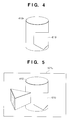
- an augmented reality presentation system presents an augmented reality image in which a virtual object 410 (e.g., a columnar block) is merged to a position behind the real object 400 to the observer.
- the augmented reality presentation system generates a depth image of the real object 400 from images taken by a camera that moves together with the observer, and discriminates the depth ordering of the real object 400 and virtual object 410 on the basis of this depth image upon presenting an image of the virtual object 410.
- the augmented reality presentation system can generate a virtual image 410 5 with an occluded portion 600, and can render these images in a correct occlusion relationship, i.e., can render a scene 520 5 (Fig. 3) in which the virtual image 410 is partially occluded by the object 400.
- a depth image to be used at the viewpoint P 5 for augmented reality presentation is the one at an old viewpoint ⁇ t before the viewpoint P 5 (the viewpoint P 2 in Fig. 1 will be used to express this old position for the sake of simplicity). That is, at the current time (i.e., the time of the viewpoint P 5 in Fig. 1), a depth image 510 2 corresponding to a scene 500 2 at the viewpoint P 2 ⁇ t before the current time can only be obtained.
- the object 400 could be observed at a rightward position as compared to the scene 500 5 , and its depth image 510 2 could correspond to the scene 500 2 .
- the depth ordering of the real and virtual worlds at the viewpoint P 5 is discriminated in accordance with this old depth image 510 2 , since a virtual image 410 2 with an occluded portion 610, is generated, as shown in Fig.
- an image of the front real object 400 is presented to the observer as the one which is occluded by the virtual image 410 2 of the virtual object 410, and by contrast, an image of the virtual object 410 presented to the observer has a portion 610 which ought not to be occluded but is in fact occluded, and the virtual object 410 also has a portion 620 which ought to be occluded but is in fact not occluded, as shown in Fig. 5.
- This article proposes predicting a future depth image. That is, this article proposes an algorithm that can reduce system latency from input to output as much as possible by executing high-speed disparity estimation that uses the stereo processing result of previous images and utilizes time correlation, parallel to disparity estimation by stereo.
- this article is premised on used of a stationary camera, and cannot cope with a situation where the camera itself (i.e., a position/posture of viewpoint of the observer) moves.
- the present invention has been made to solve the conventional problems, and has as its object to provide a depth image measurement apparatus and method, that can acquire a depth image of a real world in real time without any delay.
- the second viewpoint position at which the second depth image is to be generated is that of the image input means at the second time, to which the image input means has moved over a time elapsed from the first time at which the image input means input the stereo image.
- the second time is a time elapsed from the first time by
- the image input means (or step) inputs a stereo image from stereo cameras.
- the depth image generation means (or step) generates the stereo image or first depth image by triangulation measurement.
- the viewpoint position can be detected based on an image input by the image input means without any dedicated three-dimensional position/posture sensor.
- the position information estimation means (or step) estimates changes in viewpoint position on the basis of the stereo image input from the stereo cameras attached to the observer.
- the viewpoints can be accurately detected using a dedicated position/posture sensor.
- the position information estimation means receives a signal from a three-dimensional position/posture sensor attached to the camera, and estimates changes in viewpoints on the signal.
- the depth image warping means calculates a coordinate value and depth value of one point on the second depth image, which corresponds to each point on the first depth image, by three-dimensional coordinate transformation on the basis of the viewpoint position/posture information.
- a depth image generating apparatus for generating a depth image according to a preferred embodiment of the present invention will be explained hereinafter with reference to the accompanying drawings.
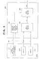
- Fig. 6 shows a basic arrangement of a depth image generation apparatus, and mainly shows a depth image generation apparatus 200 having two cameras 102R and 102L mounted on a base 100.
- the base 100 has the two cameras 102R and 102L for stereoscopically sensing a scene in front of them.
- Image signals I R and I L that represent an environmental scene of a real space sensed by the respective cameras at time t 0 are sent to the depth image generation apparatus 200.
- the viewpoint position/posture estimation module 201 outputs the relative position/posture of the viewpoint at time t F viewed from the viewpoint position/posture at time t 0 to the depth warping module 203.
- the viewpoint position/posture estimation module 201 has two input routes.
- One input route receives position information (x, y, z) and posture information ( ⁇ , ⁇ , ⁇ ) from a three-dimensional position/posture sensor 101 mounted on the base 100.
- position information (x, y, z) and posture information ( ⁇ , ⁇ , ⁇ ) will be generally referred to as "position/posture information V" hereinafter.
- the other input route to the viewpoint position/posture estimation module 201 receives the image signal I R from the camera 102R.
- the three-dimensional position/posture sensor 101 is mounted on the base 100, and is calibrated to output the viewpoint position/posture of the camera 102R. That is, the relative position relationship (offset) between the sensor itself and camera 102R is measured in advance, and this offset is added to the position/posture information of the sensor itself as its actual output, thus outputting the position/posture information V of the camera 102R.
- the viewpoint position/posture estimation module 201 When the viewpoint position/posture estimation module 201 receives the position/posture information V (x, y, z, ⁇ , ⁇ , ⁇ ) from the sensor 101, that information V represents the viewpoint position/posture of the camera 102R. On the other hand, when the viewpoint position/posture estimation module 201 receives the image signal I R , it extracts the position/posture information V of the camera 102R from that image signal I R . In this way, the viewpoint position/posture estimation module 201 time-sequentially extracts the position/posture information V of the camera 102R on the basis of the signal time-sequentially input from one of the sensor 101 and camera 102R.
- the viewpoint position/posture estimation module 201 estimates a change ⁇ V in relative viewpoint position of the camera 102R at time t F , viewed from the viewpoint position of the camera 102R at time t 0 , on the basis of the time-sequentially extracted position/posture information V of the camera 102R, and outputs it.
- the feature of the depth image generation apparatus 200 shown in Fig. 6 lies in that the change ⁇ V in viewpoint at arbitrary future time t F is estimated and a depth image ID W at that viewpoint position/posture is generated.
- the depth warping module 203 warps the depth image ID estimated by the depth estimation module 202 to generate a depth image ID W . This warping will be explained in detail later.
- the image generating apparatus shown in Fig. 6 can improve processing efficiency by pipeline processing exploiting its hardware arrangement.
- Fig. 7 shows the pipeline order when the pipeline processing is applied to the image generating apparatus shown in Fig. 6.
- the two cameras 102 inputs two, right and left image signals I R and I L . Assume that this input processing requires a time ⁇ 1 . Then, at time t 0 + ⁇ 1 + ⁇ 2 , the depth estimation module 202 outputs a depth image ID at time to to the depth warping module 203.
- the viewpoint position/posture estimation module 201 obtains the current viewpoint position/posture V t0 from that image signal (or the signal from the position/posture sensor), estimates a viewpoint position/posture V tF ⁇ t after the current time from the locus of the viewpoint so far, and outputs a change ⁇ V in viewpoint position/posture between these two viewpoints.
- the position/posture estimation module 201 requires a time ⁇ 0 for this estimation (see Fig. 7) (at this time, assume that the time ⁇ 0 is sufficiently shorter than the time ⁇ 2 ).
- the change ⁇ V in viewpoints is output to the depth warping module 203 at time t 0 + ⁇ 1 + ⁇ 2 .
- the position/posture estimation module 201 or depth warping module 203 may include a buffer memory for temporarily storing the estimation result.
- the depth warping module starts warping at time t 0 + ⁇ 1 + ⁇ 2 . More specifically, the depth warping module 203 starts processing for warping the estimated depth image ID at time t 0 by the depth estimation module 202 to a depth image at the estimated viewpoint at time t 0 + ⁇ t by the position/posture estimation module 201. If the depth warping module 203 requires a time ⁇ 3 for the processing, it outputs the warped depth image ID W at time t 0 + ⁇ 1 + ⁇ 2 + ⁇ 3 .
- the position/posture estimation module 201 and depth estimation module 202 execute parallel processes.
- the processes of the depth estimation module 202 and depth warping module 203 can be coupled in a pipeline fashion.
- the depth estimation module 202 continuously and sequentially receives images. For example, when images are input at a rate of 30 frames/sec, the depth estimation module 202 must process, within the time ⁇ 2 required for the processing: 30 x ⁇ 2 frames For this purpose, the depth estimation module 202 is further divided into a plurality of module units. If the module 202 is divided so that its processing is done by distributed processing using a maximum of 30 ⁇ ⁇ 2 module units, the depth estimation module 202 can continuously estimate depth images at the rate of 30 frames/sec. Similarly, the depth warping module is divided in accordance with the time ⁇ 3 required for its processing. With such divided module units, the depth image generation apparatus 200 of this embodiment can continuously execute two processes, i.e., depth estimation and depth warping, in a pipeline fashion.
- two processes i.e., depth estimation and depth warping
- a buffer memory or memories can be appropriately added, as described above.
- the depth estimation module 202 and depth warping module 203 generate a depth image on the basis of an image from one camera, but they may generate depth images on the basis of images from two cameras, depending on the purposes.
- the number of cameras 102 is not limited to two. In order to improve depth estimation precision, two or more cameras are preferably used.
- the depth image generation apparatus 200 shown in Fig. 6 is designed to require the time duration ⁇ t the length of which is set ⁇ 1 + ⁇ 2 + ⁇ 3 .
- the time duration ⁇ t should be determined depending on the time when a depth image is required by an application.
- estimation in the position/posture estimation module 201 suffers more errors as the time duration ⁇ t becomes larger, and this tendency becomes especially conspicuous when the moving speed of the observer is high or when the moving direction is random.
- the time duration ⁇ t must be appropriately adjusted in correspondence with the use environment of that system or the purpose of an application which uses the output depth image.
- a depth image suffering least errors can be output by allowing the user to freely set optimal ⁇ t.
- the position/posture estimation module 201 in the image processing apparatus shown in Fig. 6 predicts a position/posture of viewpoint at the time ⁇ t after the current time, the prediction being made at time t 2 + ⁇ 1 + ⁇ 2 - ⁇ 0 in Fig. 1.
- the depth warping module 203 warps a depth image 510 2 at the viewpoint P 2 obtained by the depth estimation module 202 to a depth image which will be obtained at the predicted viewpoint (i.e., the viewpoint P 5 ) the time ⁇ t after the current time.
- the depth warping module 203 is expected to output the warped depth image (this depth image is similar to the depth image 510 5 ) at time t 5 - ⁇ 4 .
- an augmented reality image can be projected to the observer's eyes so that a virtual object 410 has correct depth ordering with a real object 400.
- estimation of the depth image 510 5 must be started at time t 2 the time duration ⁇ t required for the internal processing before time t 5 .
- the depth image 510 5 starts to estimate the depth image 510 5 of the real space at time t 5 .
- the depth image generation apparatus 200 shown in Fig. 6 warps the depth image 510 2 of an image input from the camera at time t 2 , and uses the warped depth image as the depth image 510 5 of the real space at time t 5 .
- An apparatus of the first embodiment is a depth image generation apparatus that explains the principle of the embodiment shown in Figs. 6 and 7 in more detail.
- the principle of the embodiment that generates a depth image in real time without any latency or time lag from the real space is applied to an augmented reality presentation system. More specifically, the second embodiment is directed to an optical see-through augmented reality presentation system using an optical see-through HMD, and the third embodiment is directed to a video see-through augmented reality presentation system using a video see-through HMD.
- Fig. 6 is a block diagram of a depth image generation apparatus of the first embodiment.
- the aforementioned basic embodiment suggests applications with and without the three-dimensional position/posture sensor 101.
- the three-dimensional position/posture sensor 101 is used.
- the position/posture sensor 101 continuously outputs viewpoint position/posture information V ts of the camera 102 along a time axis t s of the sensor 101.
- ⁇ , ⁇ , and ⁇ are respectively the rotational angles about the X-, Y-, and Z-axes, as shown in Fig. 8.
- a viewing transformation matrix i.e., a transformation matrix from a world coordinate system to a camera coordinate system
- M ts corresponding to such viewpoint position/posture Information V ts is given by:
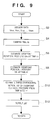
- Fig. 9 shows the control sequence of the viewpoint estimation module 201.
- step S2 position/posture information V tsm at current time t sm along the time axis of the sensor is input from the sensor 101. In this way, together with previously input position/posture information, a series of position/posture information is obtained: V ts0 , V ts1 , V ts2 ,..., V tsm
- the output from the position/posture sensor 101 is according to the time axis t s .
- position/posture information at time to at which the camera 102 captured the image can be directly used.
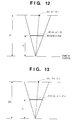
- the position/posture information at time t 0 is calculated by interpolating position/posture information obtained from the sensor before and after that time. This interpolation can be implemented by, e.g., simple a 1st-order (linear) interpolation. More specifically, when time t 0 has a relationship with time t s of the sensor 101, as shown in Fig.
- step S8 the viewpoint position/posture information V tF of the camera 102R at time t F is given, using, e.g., 1st-order linear prediction, by: where
- viewpoint having position/posture value V tF may be estimated by 2nd-order linear prediction or other prediction methods.
- step S10 a three-dimensional motion of the viewpoint position of the camera from time t 0 to time t F is estimated.
- step S12 this transformation matrix ⁇ M is output.
- the depth estimation module 202 receives image signals I R and I L from the cameras 102R and 102L, and calculates depth information by known triangulation measurement.
- Fig. 11 shows the control sequence of the depth estimation module 202. More specifically, in step S20, corresponding points existing between the two images I R and I L are extracted from the individual images. Pairs of corresponding points are pixels of points on the right and left images, which respectively correspond to a given point on an object. Such corresponding point pairs must be obtained by search in correspondence with all the pixels or feature pixels in the images I R and I L .
- a depth value Z i of a given point viewed from the camera 102R is calculated using triangulation measurement method for a pair of pixels (X Ri , Y Ri ) and (X Li , Y Li ) as corresponding points in the images I R and I L .
- the obtained depth value Z i is stored in a coordinate position (X Ri , Y Ri ) of the depth image ID.
- the depth values for all the points are calculated by repeating a loop of steps S20 to S26. That is, the depth image ID is generated.
- the generated depth image ID is output to the depth warping module 203.
- the depth estimation module 202 can be implemented using, e.g., a method disclosed in "CMU Video-Rate Stereo Machine” mentioned above, an active range finder, or a scheme proposed by Yasuyuki Sugawa, et al., "Proposal of Real-time Delay-free Stereo for Augmented Reality” in addition to triangulation measurement.
- the depth warping module 203 warps the depth image ID at the viewpoint having position/posture value V t0 received from the depth estimation module 202 to the depth image ID W at the viewpoint having position/posture value V tF .
- the principle of processing in the depth warping module 203 is as follows. That is, the basic operation of the depth warping module 203 is to inversely project the depth image ID acquired at the viewpoint having position/posture value V t0 into a space, and to re-project it onto an imaging plane assumed at the viewpoint having position/posture value V tF (i.e., to give a depth value Z Di to a point (x i ', y i ') on an output image corresponding to the depth image ID W) ).
- this point (X i ", Y i ", Z i ") is expected to move to a position (X Di , Y Di , Z Di ) on the camera coordinate system at the viewpoint having position/posture value V tF , which position is given by: Since this camera has the focal length f C , the point (X Di , Y Di , Z Di ) on the camera coordinate system at the viewpoint having position/posture value V tF is expected to be projected onto a point (x i ', y i ') on the imaging plane given by:
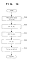
- Fig. 14 explains the processing sequence of the depth warping module 203.
- One point (x i , y i ) of the depth image ID is extracted in step S30, and is projected onto the camera coordinate system of the camera 102 at the viewpoint having position/posture value V T0 according to equation (10) above in step S32. More specifically, the coordinate position (X i “, Y i “, Z i ") of the point (x i , y i ) on the camera coordinate system is calculated.
- step S34 the coordinate position (X Di , Y Di , Z Di ) of the point (X i ", Y i ", Z i "), viewed from the camera coordinate system of the camera 102 at the viewpoint having position/posture value V tF is calculated using equation (11) above.
- step S36 the position (x i ', y i ') of the warped depth image is calculated using equation (12) above.
- step S38 pixels (x i ', y i ') on this output image are filled with Z Di . Such processes repeat themselves for all the pixels, thus warping the depth image.
- the warped depth image ID W may have "holes".
- Such image having "holes” can be corrected by compensating the values of missing pixels by linear interpolation using surrounding pixels. Also, such image having "holes” can be corrected using a scheme described in Shenchang Eric Chen & Lance Williams, "View Interpolation for Image Synthesis", Computer Graphics Annual Conference Series (Proceedings of SIGGRAPH 93), pages 279 - 288, Anaheim, California, August 1993.
- Fig. 15 shows the operation timing of the image processing apparatus of the first embodiment.
- the frame rates of the depth estimation module and depth warping module can be independently set. As shown in Fig. 15, when the frame rate of the depth warping module is set to be higher than that of the depth estimation module (in the example of Fig. 15, 6 times), a plurality of warped depth images ID W (six images in the example of Fig. 15) can be obtained from a single input image at high speed (6 times in the example of Fig. 15).
- an image obtained by the right camera 102R is to be processed.
- a depth image corresponding to an image sensed by the left camera 102L may be output by similar processing.
- depth images for both the right and left cameras may be output.
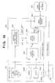
- Fig. 16 is a block diagram showing the system of the second embodiment, and the same reference numerals in Fig. 16 denote the same components as those in the embodiment shown in Fig. 6.
- a component 100 represents an optical see-through HMD.
- the system of the second embodiment is constructed by the HMD 100, a depth image generation apparatus 200, an image generation module 300, and a three-dimensional CG database 301.
- the HMD 100 comprises an LCD 103R for displaying a right-eye image, and an LCD 103L for displaying a left-eye image, since it is of optical see-through type.
- a three-dimensional position/posture sensor 101 is provided to the HMD 100.
- the depth image generation apparatus 200 (Fig. 16) of the second embodiment has the following differences from the depth image generation apparatus 200 (Fig. 6) of the aforementioned embodiment. That is, first, the second embodiment requires a depth image at each viewpoint of the observer (not shown) in place of that at each viewpoint of the camera 102R. Second, depth images must be generated in correspondence with the right and left viewpoints of the observer. Furthermore, the output from a viewpoint position/posture estimation module 201 of the second embodiment is output to the image generation module 300 in addition to a depth warping module 203 unlike in the first embodiment. The position/posture estimation module 201 outputs viewpoint position/posture information of the observer upon presentation of an image to the image generation module 300.
- the image generation module 300 uses the position/posture information input from the position/posture estimation module 201 as that for CG rendering.
- the module 300 generates an augmented reality image using the three-dimensional CG database in accordance with the distance to an object in the real world expressed by the depth image, and presents it on the LCDs 103.
- the three-dimensional CG database 301 stores, for example, CG data of the virtual object 410 shown in Fig. 1.
- the position/posture estimation module 201 of the second embodiment outputs matrices ⁇ M R and ⁇ M L that represent three-dimensional motions from a viewpoint position/posture information V t0 CR of the camera 102R at time t 0 to right and left viewpoint positions V tF UR and V tF UL of the observer at time t F to the depth warping module 203.
- matrices ⁇ M R and ⁇ M L that represent three-dimensional motions from a viewpoint position/posture information V t0 CR of the camera 102R at time t 0 to right and left viewpoint positions V tF UR and V tF UL of the observer at time t F to the depth warping module 203.
- C, U, R, and L respectively indicate the camera, user (observer), right, and left.
- the position/posture estimation module 201 outputs the right and left viewpoint positions V tF UR and V tF UL at time t F to the image generation module 300.
- the position/posture sensor 101 in the second embodiment outputs not only the viewpoint position/posture information V ts CR of the camera 102R but also information of the right and left viewpoint positions/postures V ts UR and V ts UL unlike in the first embodiment.
- the method of calculating position/posture V t0 CR of the camera 102R at time t 0 (and a corresponding viewing transformation matrix M t0 CR ) in the second embodiment is the same as that in the first embodiment.
- the viewpoint position/posture is not that of a camera but of the observer.
- the position/posture sensor 101 may output V ts CR alone.
- the position/posture estimation module 201 internally calculates V ts UR and V tS UL using the relative position relationship between the camera 102R, and the right and left viewpoint positions/postures of the observer as known information.
- depth images required as warped depth images in the second embodiment are those in the real world observed from the viewpoint position/postures of the observer via the LCDs 103. That is, when a virtual camera equivalent to the viewpoint of the observer is assumed, and f U (U is the user (observer)) represents the focal length of that virtual camera, the operation of the depth warping module 203 of the second embodiment is to inversely project a depth image ID acquired at a viewpoint having position/posture information V t0 into a space, and to re-project it onto the imaging plane of the virtual camera with the focal length f U assumed at the viewpoint having position/posture value V tF . This operation is implemented by replacing the value of the focal length f C of the camera 102 by the focal length f U of the virtual camera in equation (12) that expresses projection to the depth image ID W .
- the depth warping module of the second embodiment has the following difference. More specifically, the depth warping module of the second embodiment receives the matrices ⁇ M R and ⁇ M L representing two three-dimensional motions corresponding to the right and left viewpoint positions/postures as the matrix ⁇ M that expresses the three-dimensional motion of the viewpoint position, and outputs two depth images ID W R and ID W L corresponding to the right and left viewpoint positions/postures as the depth image ID W . These outputs can be obtained by independently warping images corresponding to the right and left viewpoints.
- Fig. 16 shows the arrangement of the image generation module 300 of the second embodiment.
- the CG renderer 302 renders a grayscale image (or color image) and depth image of CG data received from the three-dimensional database 301 on the basis of the viewpoint position/posture information V tF UR of the right eye of the observer input from the position/posture estimation module 201.
- the generated grayscale image (or color image) is supplied to a mask processor 303, and the depth image is supplied to a depth ordering discrimination processor 304.
- the depth ordering discrimination processor 304 also receives the warped depth image ID W R from the depth warping module 203. This depth image ID W R represents depth information of the real space.
- the depth ordering discrimination processor 304 compares the depth of a CG image to be displayed and that of the real space in units of pixels, generates a mask image in which "0" is set in all pixels corresponding to real depths smaller than the CG depths, and "1" is set in other pixels, and outputs that image to the mask processor 303.
- Zero pixel value of a given coordinate position on the mask image means that a CG figure rendered at the identical coordinate position on a CG image is located behind an object in the real space, and cannot be seen since it must be occluded by that object.
- the mask processor 303 mask-processes the CG image on the basis of the mask image. That is, if each coordinate position on the mask image has zero pixel value, the processor 303 sets the pixel value of an identical coordinate position on the CG image at "0".
- the output from the mask processor 303 is output to the display 103R.
- An image to be displayed on the LCD 103L which is presented onto the left eye of the observer is generated in similar processes.
- the CG renderer 302 receives the warped depth image ID W R from the depth warping module 203. At first, the CG renderer 302 renders a black object over the image which has the depth of the depth image ID W R . Then, the CG renderer 302 renders and overlays a virtual image by using ordinal depth-keying technique.
- the depth image be corrected using the viewpoint position of the observer at the presentation timing of the augmented reality image to the observer as a target viewpoint position.
- ⁇ 4 be a processing time required from when the image generation module 300 inputs the depth image ID W until the augmented reality image is presented onto the LCDs 103.
- ⁇ t ⁇ 1 + ⁇ 2 + ⁇ 3 + ⁇ 4 the augmented reality image per frame to be presented to the LCDs 103 is synchronized with the real space the observer is currently observing.
- a position/posture and focal length of the camera 102, and the right and left viewpoint positions/postures and focal length of the observer are independently processed. However, if the viewpoint of the observer matches the camera, they can be processed as identical ones.
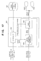
- Fig. 6 the principle of the embodiment shown in Fig. 6 is applied to a video see-through augmented reality presentation system, and Fig. 18 shows the arrangement of that system.
- the former system Upon comparing the constructing elements of the system of the third embodiment in Fig. 18 with those of the system of the second embodiment shown in Fig. 16, the former system is different from the latter one in that the former system has no head mounted position/posture sensor 101, and a viewpoint position/posture estimation module 201 can estimate movement of the viewpoint from an image acquired by one camera 102.
- the third embodiment uses a video see-through HMD, the arrangement of an image generation module is also different from the second embodiment, as will be described later.
- the position/posture estimation module 201 of the third embodiment outputs matrices ⁇ M R and ⁇ M L that represent three-dimensional motions from a viewpoint of a camera 102R having position/posture V t0 CR at time t 0 to right and left viewpoints of right and left cameras 102R and 102L having positions/postures V tF CR and V tF CL at time t F , to a depth warping module 203. Furthermore, the module 201 outputs the viewpoint positions/postures V tF CR and V tF CL of the right and left cameras 102R and 102L at time t F to an image generation module 300.
- the position/posture estimation module 201 in the first and second embodiments detects viewpoint positions/postures on the basis of the output from the position/posture sensor 101. However, the position/posture estimation module 201 of the third embodiment estimates movement of the viewpoint on the basis of images input from the cameras 102R and 102L.
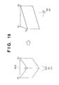
- Various schemes for estimating viewpoint position/posture on the basis of image information are available. For example, by tracking changes in coordinate value of feature points, the position on the real space of which is known, in an image, movement of the viewpoint position can be estimated.
- Fig. 19 assume that an object 600 present in the real space has vertices Q 1 , Q 2 , and Q 3 as feature points. The coordinate values of these vertices Q 1 , Q 2 , and Q 3 on the real space are known.
- a viewpoint represented by V t1 can be calculated from the coordinate values of the vertices Q 1 , Q 2 , and Q 3 at time t 1 and the known coordinate values of these vertices on the real space. Even when an image shown in Fig. 19 is obtained at time t 2 as a result of movement of the camera, a viewpoint position/posture information V t2 can be similarly calculated.
- the position/posture estimation module 201 of the third embodiment After the position/posture estimation module 201 of the third embodiment has acquired position/posture information V tC0 ,..., V tCm of viewpoints of the camera 102R at times t C0 ,..., t Cm , it outputs matrices ⁇ M ( ⁇ M R and ⁇ M L ) that describe three-dimensional movements of the cameras and the viewpoint positions/postures M tF (M tF CR and M tF CL ) of the cameras 102 to the depth warping module 203 and image generation module 300, respectively.
- ⁇ M ⁇ M R and ⁇ M L
- the processing of the depth estimation module 202 of the third embodiment is the same as that in the first embodiment, and a detailed description thereof will be omitted.
- the depth warping module in the third embodiment receives the matrices ⁇ M R and ⁇ M L representing two three-dimensional motions corresponding to the positions/postures of right and left viewpoints as the matrix ⁇ M expressing a three-dimensional motion of viewpoint, and then outputs two depth images ID W R and ID W L corresponding to the positions/postures of right and left viewpoints as the depth image ID W , as in the second embodiment.
- the viewpoint positions/postures are those of the cameras 102
- the value of the focal length f C of each camera 102 can be used as the focal length in equation (12) that expresses projection onto the depth image ID W .
- Fig. 20 shows the arrangement of the image generation module 300 of the third embodiment.
- a CG renderer 302 and depth ordering discrimination processor 304 of the third embodiment are substantially the same as those in the second embodiment.
- a merge processor 305 merges and outputs real images and images from the CG renderer 302 unlike in the second embodiment.
- the CG renderer 302 of the third embodiment renders a grayscale image (or color image) and depth image of CG data received from a three-dimensional database 301 on the basis of the viewpoint position/posture information V tF CR of the camera 102R input from the position/posture estimation module 201.
- the generated grayscale image (or color image) is sent to the merge processor 305 and the depth image is sent to the depth ordering discrimination processor 304.
- the CG renderer 302 receives the warped depth image ID W R from the depth warping module 203 and real grayscale image (or color image) from the camera. At first, the CG renderer 302 renders a real grayscale image (or color image) which has the depth of the depth image ID W R . Then, the CG renderer 302 renders and overlays a virtual image by using ordinal depth-keying technique.
- the processing of the depth ordering discrimination processor 304 is the same as that in the second embodiment, a detailed description thereof will be omitted.
- the image output from the depth ordering discrimination processor 304 is referred to not as a mask image but as a depth ordering discriminated image.
- the merge processor 305 merges the CG image (grayscale or color image) input from the renderer 302 and a real grayscale images (or color image) from the camera on the basis of the depth ordering discriminated image. That is, if each coordinate position on the depth ordering discriminated image has a pixel value "1", the processor 305 sets the pixel value at the identical coordinate position on the CG image to be that at the identical coordinate position on an output image; if the pixel value is zero, the processor 305 sets the pixel value at the identical coordinate position on the real image to be that at the identical coordinate position on the output image.
- the output from the merge processor 305 is supplied to the displays 103.
- the viewpoint position of the camera at the input timing of a real image to be merged be set as the viewpoint position/posture information V tF .
- the third embodiment estimates the viewpoint position on the basis of an image from the camera, it is suitable for a video see-through augmented reality presentation system.
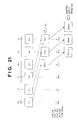
- Fig. 21 explains the operation timing of the third embodiment.
- the second and third embodiments have explained application to depth ordering discrimination between the real world and virtual image in the augmented reality presentation system.
- a depth image measurement apparatus of the present invention can also be applied to collision discrimination between the real world and virtual image in the augmented reality presentation system.
- the depth image measurement apparatus of the present invention can also be used in applications such as an environment input apparatus for a moving robot and the like, which must acquire depth information of the real environment in real time without any delay.
- the position/posture estimation module 201 in the third embodiment can also estimate the viewpoint position/posture at time t F by two-dimensional displacements of feature points on an image.
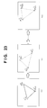
- Fig. 22 shows the control sequence of the position/posture estimation module 201 upon two-dimensionally extracting feature points.
- step S40 images are input from the camera 102 in turn. Assume that the camera 102 has sensed images I tC0 , I tC1 , I tC2 ,... at times t C0 , t C1 , t C2 ,.... From these input images, a sequence of coordinate values P A tC0 , P A tC1 , P A tC2 ,... of feature point A are obtained in step S42. In step S44, a coordinate value P A tF of feature point A at time t F is estimated. For example, this estimation may be implemented by 1st-order (linear) prediction.
- the viewpoint position/posture estimation module in the first or second embodiment uses information from the three-dimensional position/posture sensor, and that in the third embodiment uses image information from the cameras.
- these embodiments can be practiced using either scheme.
- both three-dimensional position/posture sensor and camera may be used together in a modification.
- a method disclosed in Japanese patent application Hei 10-65824 may be applied to the modification. The application is incorporated herewith by reference.
- a viewpoint position/posture is estimated based on image features in the estimation module of the embodiments or first embodiment, even if the position of a feature point on the real space is unknown, a three-dimensional motion ⁇ M of the viewpoint position/posture required for warping a depth image can be obtained.
- a relative change ⁇ M in viewpoint from time t 0 to time t F can be directly estimated. More specifically, for example, factorization (Takeo Kaneide et al., "Recovery of Object Shape and Camera Motion Based on Factorization Method", Journal of Institute of Electronics, Information and Communication Engineers D-II, No. 8, pages 1497 - 1505, 1993), Sequential Factorization (Toshihiko Morita et al., "A Sequential Factorization Method for Recovering Shape and Motion From Image Streams", IEEE Trans. PAMI, Vol. 19, No. 8, pages 858 - 867, 1998), and the like may be used.
- factorization Takeo Kaneide et al., "Recovery of Object Shape and Camera Motion Based on Factorization Method", Journal of Institute of Electronics, Information and Communication Engineers D-II, No. 8, pages 1497 - 1505, 1993
- Sequential Factorization Toshihiko Morita et al., "A Sequential Factorization Method for Recovering Shape
- feature points may be unknown ones as long as they can be identified among images by image processing.
- the depth estimation module may output depth images ID C1 , ID C2 ,... corresponding to images sensed by a plurality of cameras.
- the viewpoint position/posture estimation module outputs matrices ⁇ M C1 , ⁇ M C2 ,... that represent three-dimensional motions from the viewpoints having values V t0 C1 , V t0 C2 ,... where the respective depth images were sensed to the viewpoint having position/posture value V tF , and the depth warping module can obtain the warped depth image ID W using such information.
- the depth warping module warps the input depth images to generate warped depth images ID W C1 , ID W C2 ,... and combines these images, thus generating a warped depth image ID W as an output.
- the depth image ID W may be generated based on a depth image ID Cn acquired at a viewpoint (e.g., V t0 Cn ) with smallest three-dimensional motion, and only pixels of "holes" generated at that time may be filled using information of other depth images.
- the viewpoint position/posture estimation module may output only a matrix ⁇ M that represents a three-dimensional motion of a typical viewpoint position (of, e.g., the right camera 102R).
- the depth warping module internally calculates the matrix ⁇ M that represents each three-dimensional motion on the basis of the relative positional relationship among the viewpoint positions.
- an image to be output by the depth image generation apparatus need not always indicate the depth value itself of the real space. More specifically, for example, a disparity image that holds disparity information having a one-to-one correspondence with depth information may be output. Computations in such case can be easily implemented on the basis of the correspondence between depth information and disparity information, which is normally used in a stereo image measurement.
- warping of depth images by the depth warping modules are performed in a three-dimensional fashion on the basis of the matrices _M representing three-dimensional motions and depth values of pixels.
- the warping according to the above method can be made in more simplified manner.
- warped depth images ID W can be obtained by subjecting depth images ID to translation of two dimensional axis of image plane. This process is realized by selecting representative points of objects of interest in the depth image (objects which can be used for discriminating depth ordering with respect to imaginary objects), calculating image coordinate of the points which are subjected to viewpoint translation, and subjecting the entire depth image ID to similar translation of axis.
- Warped depth image ID W can be obtained by assuming that the real space is a plane having depths of representative points, and subjecting the image ID to three-dimensional rotation and translation of axis. Also, the image ID may be divided into a plurality of layers having a representative depth, and warped depth image ID W can be obtained by subjecting each layer to three-dimensional transform.
- depth images of the real world can be acquired in real time without any delay.
- the image processing apparatus and method and the augmented reality presentation system and method of the present invention, even when the viewpoint of the observer changes, a three-dimensionally matched augmented reality image can be presented.
- three-dimensionally matched augmented reality images can be especially continuously presented.
- the present invention can be implemented by a computer program operating on a standard desk top computer.
- An aspect of the present invention thus provides a storage medium storing processor implementable instructions for controlling a processor to carry out the method as hereinabove described.
- the computer program can be obtained in electronic form for example by downloading the code over a network such as the internet.
- an electrical signal carrying processor implementable instructions for controlling a processor to carry out the method as hereinbefore described.
Landscapes
- Engineering & Computer Science (AREA)
- Multimedia (AREA)
- Signal Processing (AREA)
- Computer Vision & Pattern Recognition (AREA)
- Physics & Mathematics (AREA)
- General Physics & Mathematics (AREA)
- Theoretical Computer Science (AREA)
- Testing, Inspecting, Measuring Of Stereoscopic Televisions And Televisions (AREA)
- Processing Or Creating Images (AREA)
- Image Processing (AREA)
- Image Analysis (AREA)
- Length Measuring Devices By Optical Means (AREA)
Applications Claiming Priority (2)
| Application Number | Priority Date | Filing Date | Title |
|---|---|---|---|
| JP12626498 | 1998-05-08 | ||
| JP12626498A JP3745117B2 (ja) | 1998-05-08 | 1998-05-08 | 画像処理装置及び画像処理方法 |
Publications (2)
| Publication Number | Publication Date |
|---|---|
| EP0955606A2 true EP0955606A2 (fr) | 1999-11-10 |
| EP0955606A3 EP0955606A3 (fr) | 2003-11-12 |
Family
ID=14930888
Family Applications (1)
| Application Number | Title | Priority Date | Filing Date |
|---|---|---|---|
| EP99301827A Withdrawn EP0955606A3 (fr) | 1998-05-08 | 1999-03-11 | Mesure de la profondeur d'image en considérant un délai |
Country Status (3)
| Country | Link |
|---|---|
| US (1) | US6445815B1 (fr) |
| EP (1) | EP0955606A3 (fr) |
| JP (1) | JP3745117B2 (fr) |
Cited By (9)
| Publication number | Priority date | Publication date | Assignee | Title |
|---|---|---|---|---|
| US6822643B2 (en) | 2000-11-17 | 2004-11-23 | Canon Kabushiki Kaisha | Image-display control apparatus |
| WO2010071531A1 (fr) * | 2008-12-19 | 2010-06-24 | Saab Ab | Système et procédé de mixage d'une scène et d'un scénario virtuel |
| WO2014105646A1 (fr) * | 2012-12-26 | 2014-07-03 | Microsoft Corporation | Fusion à faible latence de données d'image couleur |
| WO2016111640A1 (fr) * | 2015-01-07 | 2016-07-14 | Viscando Ab | Procédé et système de catégorisation d'une scène |
| WO2018203324A1 (fr) * | 2017-05-01 | 2018-11-08 | Infinity Augmented Reality Israel Ltd. | Alignement temporel de moteur optique destiné à un environnement à réalité augmentée ou mixte |
| EP3352050A4 (fr) * | 2015-09-16 | 2019-05-22 | Sony Corporation | Dispositif de traitement d'informations, procédé de traitement d'informations et programme |
| US10657366B2 (en) * | 2013-01-17 | 2020-05-19 | Canon Kabushiki Kaisha | Information processing apparatus, information processing method, and storage medium |
| US11107290B1 (en) | 2020-02-27 | 2021-08-31 | Samsung Electronics Company, Ltd. | Depth map re-projection on user electronic devices |
| WO2021172950A1 (fr) * | 2020-02-27 | 2021-09-02 | Samsung Electronics Co., Ltd. | Dispositif électronique et procédé pour reprojection de carte de profondeur sur un dispositif électronique |
Families Citing this family (147)
| Publication number | Priority date | Publication date | Assignee | Title |
|---|---|---|---|---|
| JP3363861B2 (ja) * | 2000-01-13 | 2003-01-08 | キヤノン株式会社 | 複合現実感提示装置及び複合現実感提示方法並びに記憶媒体 |
| JP2001344597A (ja) * | 2000-05-30 | 2001-12-14 | Fuji Heavy Ind Ltd | 融合視界装置 |
| US7200261B2 (en) * | 2000-08-25 | 2007-04-03 | Fujifilm Corporation | Parallax image capturing apparatus and parallax image processing apparatus |
| US7101988B2 (en) * | 2000-10-12 | 2006-09-05 | Marical, Inc. | Polyvalent cation-sensing receptor in Atlantic salmon |
| US7085409B2 (en) * | 2000-10-18 | 2006-08-01 | Sarnoff Corporation | Method and apparatus for synthesizing new video and/or still imagery from a collection of real video and/or still imagery |
| US20020055861A1 (en) * | 2000-11-08 | 2002-05-09 | King Daniel A. | Claiming system and method |
| WO2002096096A1 (fr) * | 2001-05-16 | 2002-11-28 | Zaxel Systems, Inc. | Systeme et procede de reprise instantanee 3d |
| US8300042B2 (en) * | 2001-06-05 | 2012-10-30 | Microsoft Corporation | Interactive video display system using strobed light |
| US8035612B2 (en) | 2002-05-28 | 2011-10-11 | Intellectual Ventures Holding 67 Llc | Self-contained interactive video display system |
| US7173672B2 (en) * | 2001-08-10 | 2007-02-06 | Sony Corporation | System and method for transitioning between real images and virtual images |
| US7091989B2 (en) | 2001-08-10 | 2006-08-15 | Sony Corporation | System and method for data assisted chroma-keying |
| US7339609B2 (en) * | 2001-08-10 | 2008-03-04 | Sony Corporation | System and method for enhancing real-time data feeds |
| US20030030658A1 (en) * | 2001-08-10 | 2003-02-13 | Simon Gibbs | System and method for mixed reality broadcast |
| US7251352B2 (en) * | 2001-08-16 | 2007-07-31 | Siemens Corporate Research, Inc. | Marking 3D locations from ultrasound images |
| US6940538B2 (en) * | 2001-08-29 | 2005-09-06 | Sony Corporation | Extracting a depth map from known camera and model tracking data |
| JP3705180B2 (ja) * | 2001-09-27 | 2005-10-12 | セイコーエプソン株式会社 | 画像表示システム、プログラム、情報記憶媒体および画像処理方法 |
| US20030187820A1 (en) | 2002-03-29 | 2003-10-02 | Michael Kohut | Media management system and process |
| JP2003337963A (ja) * | 2002-05-17 | 2003-11-28 | Seiko Epson Corp | 画像処理装置および画像処理方法、ならびに、画像処理プログラムおよびその記録媒体 |
| US20050122308A1 (en) * | 2002-05-28 | 2005-06-09 | Matthew Bell | Self-contained interactive video display system |
| US7710391B2 (en) * | 2002-05-28 | 2010-05-04 | Matthew Bell | Processing an image utilizing a spatially varying pattern |
| AU2003301043A1 (en) * | 2002-12-13 | 2004-07-09 | Reactrix Systems | Interactive directed light/sound system |
| US7515156B2 (en) * | 2003-01-08 | 2009-04-07 | Hrl Laboratories, Llc | Method and apparatus for parallel speculative rendering of synthetic images |
| JP2004228948A (ja) * | 2003-01-23 | 2004-08-12 | Seiko Epson Corp | 画像処理システム、プロジェクタ、プログラム、情報記憶媒体および画像処理方法 |
| US7425984B2 (en) * | 2003-04-04 | 2008-09-16 | Stmicroelectronics, Inc. | Compound camera and methods for implementing auto-focus, depth-of-field and high-resolution functions |
| JP4451730B2 (ja) * | 2003-09-25 | 2010-04-14 | 富士フイルム株式会社 | 動画生成装置、方法及びプログラム |
| CN1902930B (zh) | 2003-10-24 | 2010-12-15 | 瑞克楚斯系统公司 | 管理交互式视频显示系统的方法和系统 |
| KR100682994B1 (ko) | 2004-11-04 | 2007-02-15 | 한국전자통신연구원 | 영상 사실감 예측 장치 및 그 방법 |
| JP4227561B2 (ja) | 2004-06-03 | 2009-02-18 | キヤノン株式会社 | 画像処理方法、画像処理装置 |
| JP4573599B2 (ja) * | 2004-08-17 | 2010-11-04 | エイディシーテクノロジー株式会社 | 表示装置 |
| US7868904B2 (en) | 2005-04-01 | 2011-01-11 | Canon Kabushiki Kaisha | Image processing method and image processing apparatus |
| US9128519B1 (en) | 2005-04-15 | 2015-09-08 | Intellectual Ventures Holding 67 Llc | Method and system for state-based control of objects |
| JP5111739B2 (ja) * | 2005-05-12 | 2013-01-09 | 三菱電機株式会社 | 質感表示装置 |
| US8081822B1 (en) | 2005-05-31 | 2011-12-20 | Intellectual Ventures Holding 67 Llc | System and method for sensing a feature of an object in an interactive video display |
| US8098277B1 (en) | 2005-12-02 | 2012-01-17 | Intellectual Ventures Holding 67 Llc | Systems and methods for communication between a reactive video system and a mobile communication device |
| DE102006006001B3 (de) * | 2006-02-08 | 2007-10-04 | Fraunhofer-Gesellschaft zur Förderung der angewandten Forschung e.V. | Verfahren und Anordnung zum Einblenden ortsbezogener Informationen in eine visuelle Darstellung oder Ansicht einer Szene |
| JP4810295B2 (ja) * | 2006-05-02 | 2011-11-09 | キヤノン株式会社 | 情報処理装置及びその制御方法、画像処理装置、プログラム、記憶媒体 |
| US7894662B2 (en) * | 2006-10-11 | 2011-02-22 | Tandent Vision Science, Inc. | Method for using image depth information in identifying illumination fields |
| JP4857196B2 (ja) * | 2007-05-31 | 2012-01-18 | キヤノン株式会社 | 頭部装着型表示装置、及びその制御方法 |
| US8036452B2 (en) * | 2007-08-10 | 2011-10-11 | Leica Geosystems Ag | Method and measurement system for contactless coordinate measurement on an object surface |
| US9020240B2 (en) | 2007-08-10 | 2015-04-28 | Leica Geosystems Ag | Method and surveying system for noncontact coordinate measurement on an object surface |
| EP2402710B1 (fr) * | 2007-08-10 | 2015-10-28 | Leica Geosystems AG | Procédé et système de mesure destinés à la mesure des coordonnées sans contact à la surface d'un objet |
| KR101141087B1 (ko) | 2007-09-14 | 2012-07-12 | 인텔렉츄얼 벤처스 홀딩 67 엘엘씨 | 제스처-기반 사용자 상호작용의 프로세싱 |
| US7929804B2 (en) * | 2007-10-03 | 2011-04-19 | Mitsubishi Electric Research Laboratories, Inc. | System and method for tracking objects with a synthetic aperture |
| US8159682B2 (en) | 2007-11-12 | 2012-04-17 | Intellectual Ventures Holding 67 Llc | Lens system |
| US8351685B2 (en) * | 2007-11-16 | 2013-01-08 | Gwangju Institute Of Science And Technology | Device and method for estimating depth map, and method for generating intermediate image and method for encoding multi-view video using the same |
| KR101367284B1 (ko) * | 2008-01-28 | 2014-02-26 | 삼성전자주식회사 | 시점 변화에 따른 영상 복원 방법 및 장치 |
| US8259163B2 (en) | 2008-03-07 | 2012-09-04 | Intellectual Ventures Holding 67 Llc | Display with built in 3D sensing |
| US11792538B2 (en) | 2008-05-20 | 2023-10-17 | Adeia Imaging Llc | Capturing and processing of images including occlusions focused on an image sensor by a lens stack array |
| US8866920B2 (en) | 2008-05-20 | 2014-10-21 | Pelican Imaging Corporation | Capturing and processing of images using monolithic camera array with heterogeneous imagers |
| CN102047288B (zh) * | 2008-05-28 | 2014-04-23 | 汤姆森特许公司 | 利用正向和反向深度预测进行图像的深度提取的系统和方法 |
| US8595218B2 (en) | 2008-06-12 | 2013-11-26 | Intellectual Ventures Holding 67 Llc | Interactive display management systems and methods |
| US20110205226A1 (en) * | 2008-10-28 | 2011-08-25 | Koninklijke Philips Electronics N.V. | Generation of occlusion data for image properties |
| KR101574068B1 (ko) * | 2008-12-26 | 2015-12-03 | 삼성전자주식회사 | 영상 처리 방법 및 장치 |
| JP5215211B2 (ja) * | 2009-03-04 | 2013-06-19 | Kddi株式会社 | 関連情報表示位置特定システムおよび関連情報表示位置特定用プログラム |
| JP5310130B2 (ja) * | 2009-03-11 | 2013-10-09 | オムロン株式会社 | 3次元視覚センサによる認識結果の表示方法および3次元視覚センサ |
| JP5245938B2 (ja) * | 2009-03-12 | 2013-07-24 | オムロン株式会社 | 3次元認識結果の表示方法および3次元視覚センサ |
| JP5245937B2 (ja) * | 2009-03-12 | 2013-07-24 | オムロン株式会社 | 3次元計測処理のパラメータの導出方法および3次元視覚センサ |
| JP2010210585A (ja) * | 2009-03-12 | 2010-09-24 | Omron Corp | 3次元視覚センサにおけるモデル表示方法および3次元視覚センサ |
| JP5714232B2 (ja) | 2009-03-12 | 2015-05-07 | オムロン株式会社 | キャリブレーション装置および3次元計測のためのパラメータの精度の確認支援方法 |
| JP5316118B2 (ja) * | 2009-03-12 | 2013-10-16 | オムロン株式会社 | 3次元視覚センサ |
| JP5282614B2 (ja) * | 2009-03-13 | 2013-09-04 | オムロン株式会社 | 視覚認識処理用のモデルデータの登録方法および視覚センサ |
| JP5247590B2 (ja) * | 2009-05-21 | 2013-07-24 | キヤノン株式会社 | 情報処理装置及びキャリブレーション処理方法 |
| US8422641B2 (en) * | 2009-06-15 | 2013-04-16 | Calabrio, Inc. | Distributed record server architecture for recording call sessions over a VoIP network |
| KR101565969B1 (ko) * | 2009-09-01 | 2015-11-05 | 삼성전자주식회사 | 깊이 정보를 추정할 수 있는 방법과 장치, 및 상기 장치를 포함하는 신호 처리 장치 |
| JP2011060216A (ja) * | 2009-09-14 | 2011-03-24 | Fujifilm Corp | 画像処理装置および画像処理方法 |
| US8643701B2 (en) | 2009-11-18 | 2014-02-04 | University Of Illinois At Urbana-Champaign | System for executing 3D propagation for depth image-based rendering |
| EP2502115A4 (fr) | 2009-11-20 | 2013-11-06 | Pelican Imaging Corp | Capture et traitement d'images au moyen d'un réseau de caméras monolithique équipé d'imageurs hétérogènes |
| US8280112B2 (en) * | 2010-03-31 | 2012-10-02 | Disney Enterprises, Inc. | System and method for predicting object location |
| EP2572336B1 (fr) * | 2010-05-18 | 2021-09-15 | Teknologian Tutkimuskeskus VTT | Dispositif mobile, agencement de serveur et procédé pour applications de réalité augmentée |
| CN102438153B (zh) * | 2010-09-29 | 2015-11-25 | 华为终端有限公司 | 多摄像机图像校正方法和设备 |
| US8878950B2 (en) | 2010-12-14 | 2014-11-04 | Pelican Imaging Corporation | Systems and methods for synthesizing high resolution images using super-resolution processes |
| US9235749B2 (en) * | 2011-02-24 | 2016-01-12 | Sony Corporation | Image processing device and image processing method |
| US9262950B2 (en) | 2011-04-20 | 2016-02-16 | Microsoft Technology Licensing, Llc | Augmented reality extrapolation techniques |
| JPWO2012147363A1 (ja) * | 2011-04-28 | 2014-07-28 | パナソニック株式会社 | 画像生成装置 |
| US9509972B2 (en) * | 2011-06-24 | 2016-11-29 | Lg Electronics Inc. | Encoding/decoding method and apparatus using a skip mode |
| US9300946B2 (en) | 2011-07-08 | 2016-03-29 | Personify, Inc. | System and method for generating a depth map and fusing images from a camera array |
| WO2013043751A1 (fr) | 2011-09-19 | 2013-03-28 | Pelican Imaging Corporation | Systèmes et procédés permettant de commander le crénelage des images capturées par une caméra disposée en réseau destinée à être utilisée dans le traitement à super-résolution à l'aide d'ouvertures de pixel |
| CN104081414B (zh) | 2011-09-28 | 2017-08-01 | Fotonation开曼有限公司 | 用于编码和解码光场图像文件的系统及方法 |
| US9412206B2 (en) | 2012-02-21 | 2016-08-09 | Pelican Imaging Corporation | Systems and methods for the manipulation of captured light field image data |
| JP5977591B2 (ja) * | 2012-06-20 | 2016-08-24 | オリンパス株式会社 | 画像処理装置及びそれを備えた撮像装置、画像処理方法、並びに画像処理プログラムを記録したコンピュータ読み取り可能な記録媒体 |
| US20140002674A1 (en) | 2012-06-30 | 2014-01-02 | Pelican Imaging Corporation | Systems and Methods for Manufacturing Camera Modules Using Active Alignment of Lens Stack Arrays and Sensors |
| CN107346061B (zh) | 2012-08-21 | 2020-04-24 | 快图有限公司 | 用于使用阵列照相机捕捉的图像中的视差检测和校正的系统和方法 |
| EP2888698A4 (fr) | 2012-08-23 | 2016-06-29 | Pelican Imaging Corp | Estimation de mouvement en haute résolution basée sur des éléments à partir d'images en basse résolution capturées à l'aide d'une source matricielle |
| WO2014052974A2 (fr) * | 2012-09-28 | 2014-04-03 | Pelican Imaging Corporation | Création d'images à partir de champs de lumière en utilisant des points de vue virtuels |
| US9398264B2 (en) | 2012-10-19 | 2016-07-19 | Qualcomm Incorporated | Multi-camera system using folded optics |
| US20140168264A1 (en) | 2012-12-19 | 2014-06-19 | Lockheed Martin Corporation | System, method and computer program product for real-time alignment of an augmented reality device |
| US8866912B2 (en) | 2013-03-10 | 2014-10-21 | Pelican Imaging Corporation | System and methods for calibration of an array camera using a single captured image |
| WO2014159779A1 (fr) | 2013-03-14 | 2014-10-02 | Pelican Imaging Corporation | Systèmes et procédés de réduction du flou cinétique dans des images ou une vidéo par luminosité ultra faible avec des caméras en réseau |
| US9497429B2 (en) | 2013-03-15 | 2016-11-15 | Pelican Imaging Corporation | Extended color processing on pelican array cameras |
| US9473708B1 (en) * | 2013-08-07 | 2016-10-18 | Google Inc. | Devices and methods for an imaging system with a dual camera architecture |
| US10178373B2 (en) | 2013-08-16 | 2019-01-08 | Qualcomm Incorporated | Stereo yaw correction using autofocus feedback |
| JP6102648B2 (ja) * | 2013-09-13 | 2017-03-29 | ソニー株式会社 | 情報処理装置及び情報処理方法 |
| US10119808B2 (en) | 2013-11-18 | 2018-11-06 | Fotonation Limited | Systems and methods for estimating depth from projected texture using camera arrays |
| EP3075140B1 (fr) | 2013-11-26 | 2018-06-13 | FotoNation Cayman Limited | Configurations de caméras en réseau comprenant de multiples caméras en réseau constitutives |
| US9332285B1 (en) | 2014-05-28 | 2016-05-03 | Lucasfilm Entertainment Company Ltd. | Switching modes of a media content item |
| JP6384856B2 (ja) * | 2014-07-10 | 2018-09-05 | Kddi株式会社 | 予測カメラ姿勢に基づくarオブジェクトを実時間に合わせて描画する情報装置、プログラム及び方法 |
| CN113256730B (zh) | 2014-09-29 | 2023-09-05 | 快图有限公司 | 用于阵列相机的动态校准的系统和方法 |
| US9588598B2 (en) | 2015-06-30 | 2017-03-07 | Ariadne's Thread (Usa), Inc. | Efficient orientation estimation system using magnetic, angular rate, and gravity sensors |
| US9607428B2 (en) | 2015-06-30 | 2017-03-28 | Ariadne's Thread (Usa), Inc. | Variable resolution virtual reality display system |
| US9588593B2 (en) | 2015-06-30 | 2017-03-07 | Ariadne's Thread (Usa), Inc. | Virtual reality system with control command gestures |
| US9396588B1 (en) | 2015-06-30 | 2016-07-19 | Ariadne's Thread (Usa), Inc. (Dba Immerex) | Virtual reality virtual theater system |
| US10089790B2 (en) | 2015-06-30 | 2018-10-02 | Ariadne's Thread (Usa), Inc. | Predictive virtual reality display system with post rendering correction |
| US9240069B1 (en) * | 2015-06-30 | 2016-01-19 | Ariadne's Thread (Usa), Inc. | Low-latency virtual reality display system |
| CN104952221B (zh) * | 2015-07-09 | 2017-06-13 | 深圳大学 | 智能防近视台灯 |
| US9454010B1 (en) | 2015-08-07 | 2016-09-27 | Ariadne's Thread (Usa), Inc. | Wide field-of-view head mounted display system |
| US9606362B2 (en) | 2015-08-07 | 2017-03-28 | Ariadne's Thread (Usa), Inc. | Peripheral field-of-view illumination system for a head mounted display |
| US9990008B2 (en) | 2015-08-07 | 2018-06-05 | Ariadne's Thread (Usa), Inc. | Modular multi-mode virtual reality headset |
| US10345786B2 (en) | 2016-02-16 | 2019-07-09 | International Business Machines Corporation | Method and system for proactive heating-based crack prevention in 3D printing |
| US10242499B2 (en) | 2016-02-16 | 2019-03-26 | International Business Machines Corporation | Method and system for geographic map overlay onto a live feed |
| US9459692B1 (en) | 2016-03-29 | 2016-10-04 | Ariadne's Thread (Usa), Inc. | Virtual reality headset with relative motion head tracker |
| CN105892683A (zh) * | 2016-04-29 | 2016-08-24 | 上海乐相科技有限公司 | 一种显示方法及目标设备 |
| US10043318B2 (en) * | 2016-12-09 | 2018-08-07 | Qualcomm Incorporated | Display synchronized image warping |
| EP3577896A4 (fr) | 2017-02-03 | 2020-11-25 | Warner Bros. Entertainment Inc. | Rendu de vidéo étendue en réalité virtuelle |
| US10929987B2 (en) | 2017-08-16 | 2021-02-23 | Nvidia Corporation | Learning rigidity of dynamic scenes for three-dimensional scene flow estimation |
| JP6732716B2 (ja) * | 2017-10-25 | 2020-07-29 | 株式会社ソニー・インタラクティブエンタテインメント | 画像生成装置、画像生成システム、画像生成方法、およびプログラム |
| US10559276B2 (en) | 2018-02-03 | 2020-02-11 | Facebook Technologies, Llc | Apparatus, system, and method for mitigating motion-to-photon latency in head-mounted displays |
| EP3522150A3 (fr) * | 2018-02-03 | 2020-01-01 | Facebook Technologies, LLC | Appareil, système et procédé d'atténuation de la latence entre mouvement et photon dans des visiocasques |
| US10706813B1 (en) | 2018-02-03 | 2020-07-07 | Facebook Technologies, Llc | Apparatus, system, and method for mitigating motion-to-photon latency in head-mounted displays |
| CN108289175B (zh) * | 2018-02-05 | 2020-12-08 | 黄淮学院 | 一种低延迟虚拟现实显示方法及显示系统 |
| JP7132730B2 (ja) * | 2018-03-14 | 2022-09-07 | キヤノン株式会社 | 情報処理装置および情報処理方法 |
| US10678325B2 (en) | 2018-05-22 | 2020-06-09 | Facebook Technologies, Llc | Apparatus, system, and method for accelerating positional tracking of head-mounted displays |
| CN108921951B (zh) * | 2018-07-02 | 2023-06-20 | 京东方科技集团股份有限公司 | 虚拟现实图像显示方法及其装置、虚拟现实设备 |
| DE102018122435A1 (de) * | 2018-09-13 | 2020-03-19 | Hendrik Fehlis | Virtuelle dreidimensionale Objekte in einem Livevideo |
| US10510155B1 (en) * | 2019-06-11 | 2019-12-17 | Mujin, Inc. | Method and processing system for updating a first image generated by a first camera based on a second image generated by a second camera |
| WO2021055585A1 (fr) | 2019-09-17 | 2021-03-25 | Boston Polarimetrics, Inc. | Systèmes et procédés de modélisation de surface utilisant des repères de polarisation |
| CN110751039B (zh) * | 2019-09-18 | 2023-07-25 | 平安科技(深圳)有限公司 | 多视图3d人体姿态估计方法及相关装置 |
| WO2021071995A1 (fr) | 2019-10-07 | 2021-04-15 | Boston Polarimetrics, Inc. | Systèmes et procédés de détection de normales à une surface à l'aide d'une polarisation |
| CN110751685B (zh) * | 2019-10-21 | 2022-10-14 | 广州小鹏汽车科技有限公司 | 深度信息确定方法、确定装置、电子装置和车辆 |
| EP4066001B1 (fr) | 2019-11-30 | 2026-03-04 | Intrinsic Innovation LLC | Systèmes et procédés de segmentation d'objets transparents au moyen de files d'attentes de polarisation |
| US12148120B2 (en) * | 2019-12-18 | 2024-11-19 | Ati Technologies Ulc | Frame reprojection for virtual reality and augmented reality |
| JP7462769B2 (ja) | 2020-01-29 | 2024-04-05 | イントリンジック イノベーション エルエルシー | 物体の姿勢の検出および測定システムを特徴付けるためのシステムおよび方法 |
| US11797863B2 (en) | 2020-01-30 | 2023-10-24 | Intrinsic Innovation Llc | Systems and methods for synthesizing data for training statistical models on different imaging modalities including polarized images |
| CN113289330B (zh) * | 2020-02-21 | 2023-12-08 | 华为技术有限公司 | 渲染方法和装置 |
| WO2021243088A1 (fr) | 2020-05-27 | 2021-12-02 | Boston Polarimetrics, Inc. | Systèmes optiques de polarisation à ouvertures multiples utilisant des diviseurs de faisceau |
| US12069227B2 (en) | 2021-03-10 | 2024-08-20 | Intrinsic Innovation Llc | Multi-modal and multi-spectral stereo camera arrays |
| US12020455B2 (en) | 2021-03-10 | 2024-06-25 | Intrinsic Innovation Llc | Systems and methods for high dynamic range image reconstruction |
| CN113221953B (zh) * | 2021-04-14 | 2023-01-31 | 上海交通大学宁波人工智能研究院 | 基于实例分割和双目深度估计的目标姿态识别系统与方法 |
| US11290658B1 (en) | 2021-04-15 | 2022-03-29 | Boston Polarimetrics, Inc. | Systems and methods for camera exposure control |
| US11954886B2 (en) | 2021-04-15 | 2024-04-09 | Intrinsic Innovation Llc | Systems and methods for six-degree of freedom pose estimation of deformable objects |
| US12067746B2 (en) | 2021-05-07 | 2024-08-20 | Intrinsic Innovation Llc | Systems and methods for using computer vision to pick up small objects |
| US12175741B2 (en) | 2021-06-22 | 2024-12-24 | Intrinsic Innovation Llc | Systems and methods for a vision guided end effector |
| US12340538B2 (en) | 2021-06-25 | 2025-06-24 | Intrinsic Innovation Llc | Systems and methods for generating and using visual datasets for training computer vision models |
| US12172310B2 (en) | 2021-06-29 | 2024-12-24 | Intrinsic Innovation Llc | Systems and methods for picking objects using 3-D geometry and segmentation |
| US11689813B2 (en) | 2021-07-01 | 2023-06-27 | Intrinsic Innovation Llc | Systems and methods for high dynamic range imaging using crossed polarizers |
| US12293535B2 (en) | 2021-08-03 | 2025-05-06 | Intrinsic Innovation Llc | Systems and methods for training pose estimators in computer vision |
| CN114972522B (zh) * | 2021-09-23 | 2025-07-08 | 深圳市联洲国际技术有限公司 | 图像传感器的位姿标定方法、装置、存储介质及终端设备 |
| CN117351054A (zh) * | 2022-06-27 | 2024-01-05 | 威马智慧出行科技(上海)股份有限公司 | 图像像素点的深度信息获取方法、装置及设备 |
Family Cites Families (5)
| Publication number | Priority date | Publication date | Assignee | Title |
|---|---|---|---|---|
| JP3573512B2 (ja) * | 1994-05-17 | 2004-10-06 | オリンパス株式会社 | 画像処理方法及び画像処理装置 |
| US5703961A (en) * | 1994-12-29 | 1997-12-30 | Worldscape L.L.C. | Image transformation and synthesis methods |
| US5933185A (en) * | 1995-05-31 | 1999-08-03 | Sony Corporation | Special effect apparatus |
| US6084979A (en) * | 1996-06-20 | 2000-07-04 | Carnegie Mellon University | Method for creating virtual reality |
| JP3064928B2 (ja) * | 1996-09-20 | 2000-07-12 | 日本電気株式会社 | 被写体抽出方式 |
-
1998
- 1998-05-08 JP JP12626498A patent/JP3745117B2/ja not_active Expired - Fee Related
-
1999
- 1999-03-11 EP EP99301827A patent/EP0955606A3/fr not_active Withdrawn
- 1999-03-12 US US09/266,859 patent/US6445815B1/en not_active Expired - Lifetime
Non-Patent Citations (7)
| Title |
|---|
| ALVERTOS N: "Resolution limitations and error analysis for stereo camera models" DEPARTMENT OF ELECTRICAL AND COMPUTER ENGINEERING - OLD DOMINION UNIVERSITY, 1988, pages 220-224, XP010075157 Norfolk, Virginia * |
| BAKOS G C ET AL: "LONG DISTANCE NON-CONTACT HIGH PRECISION MEASUREMENTS" INTERNATIONAL JOURNAL OF ELECTRONICS, TAYLOR AND FRANCIS.LTD. LONDON, GB, vol. 75, no. 6, 1 December 1993 (1993-12-01), pages 1269-1279, XP000421502 ISSN: 0020-7217 * |
| JANIN A L ET AL: "Calibration of head-mounted displays for augmented reality applications" VIRTUAL REALITY ANNUAL INTERNATIONAL SYMPOSIUM, 1993., 1993 IEEE SEATTLE, WA, USA 18-22 SEPT. 1993, NEW YORK, NY, USA,IEEE, 18 September 1993 (1993-09-18), pages 246-255, XP010130485 ISBN: 0-7803-1363-1 * |
| PARK J-I ET AL: "Arbitrary view generation from multiple cameras" IMAGE PROCESSING, 1997. PROCEEDINGS., INTERNATIONAL CONFERENCE ON SANTA BARBARA, CA, USA 26-29 OCT. 1997, LOS ALAMITOS, CA, USA,IEEE COMPUT. SOC, US, 26 October 1997 (1997-10-26), pages 149-152, XP010254130 ISBN: 0-8186-8183-7 * |
| RONALD T. AZUMA: "A Survey of Augmented Reality" PRESENCE: TELEOPERATORS AND VIRTUAL ENVIRONMENT, [Online] August 1997 (1997-08), pages 1-48, XP002254668 Malibu Retrieved from the Internet: <URL:http://www.cs.unc.edu/~azuma/azuma_pu blications.html> [retrieved on 2003-09-16] * |
| RONALD T. AZUMA: "Predictive Tracking for Augmented Reality" UNC CHAPEL HILL DEPT. OF COMPUTER SCIENCE TECHNICAL REPORT TR95-007, [Online] February 1995 (1995-02), pages 1-262, XP002254667 Retrieved from the Internet: <URL:http://www.cs.unc.edu/~azuma/azuma_pu blications.html> [retrieved on 2003-09-16] * |
| SCHALKOFF R J ET AL: "A model-based viewpoint determination method for multiple object 3-D motion estimation" IEEE PROCEEDINGS - 1989 SOUTHEASTCON, 1989, pages 1074-1079, XP010082305 * |
Cited By (16)
| Publication number | Priority date | Publication date | Assignee | Title |
|---|---|---|---|---|
| US6822643B2 (en) | 2000-11-17 | 2004-11-23 | Canon Kabushiki Kaisha | Image-display control apparatus |
| US10187589B2 (en) * | 2008-12-19 | 2019-01-22 | Saab Ab | System and method for mixing a scene with a virtual scenario |
| WO2010071531A1 (fr) * | 2008-12-19 | 2010-06-24 | Saab Ab | Système et procédé de mixage d'une scène et d'un scénario virtuel |
| US20120115598A1 (en) * | 2008-12-19 | 2012-05-10 | Saab Ab | System and method for mixing a scene with a virtual scenario |
| AU2008365306B2 (en) * | 2008-12-19 | 2014-02-13 | Saab Ab | System and method for mixing a scene with a virtual scenario |
| WO2014105646A1 (fr) * | 2012-12-26 | 2014-07-03 | Microsoft Corporation | Fusion à faible latence de données d'image couleur |
| US10657366B2 (en) * | 2013-01-17 | 2020-05-19 | Canon Kabushiki Kaisha | Information processing apparatus, information processing method, and storage medium |
| US10127458B2 (en) | 2015-01-07 | 2018-11-13 | Viscando Ab | Method and system for categorization of a scene |
| WO2016111640A1 (fr) * | 2015-01-07 | 2016-07-14 | Viscando Ab | Procédé et système de catégorisation d'une scène |
| EP3352050A4 (fr) * | 2015-09-16 | 2019-05-22 | Sony Corporation | Dispositif de traitement d'informations, procédé de traitement d'informations et programme |
| WO2018203324A1 (fr) * | 2017-05-01 | 2018-11-08 | Infinity Augmented Reality Israel Ltd. | Alignement temporel de moteur optique destiné à un environnement à réalité augmentée ou mixte |
| CN110573929A (zh) * | 2017-05-01 | 2019-12-13 | 无限增强现实以色列有限公司 | 增强或混合现实环境的光学引擎时间扭曲 |
| US20200050264A1 (en) * | 2017-05-01 | 2020-02-13 | Infinity Augmented Reality Israel Ltd. | Optical engine time warp for augmented or mixed reality environment |
| US10928892B2 (en) | 2017-05-01 | 2021-02-23 | Alibaba Technology (Israel) Ltd. | Optical engine time warp for augmented or mixed reality environment |
| US11107290B1 (en) | 2020-02-27 | 2021-08-31 | Samsung Electronics Company, Ltd. | Depth map re-projection on user electronic devices |
| WO2021172950A1 (fr) * | 2020-02-27 | 2021-09-02 | Samsung Electronics Co., Ltd. | Dispositif électronique et procédé pour reprojection de carte de profondeur sur un dispositif électronique |
Also Published As
| Publication number | Publication date |
|---|---|
| JP3745117B2 (ja) | 2006-02-15 |
| JPH11331874A (ja) | 1999-11-30 |
| US6445815B1 (en) | 2002-09-03 |
| EP0955606A3 (fr) | 2003-11-12 |
Similar Documents
| Publication | Publication Date | Title |
|---|---|---|
| US6445815B1 (en) | Measurement of depth image considering time delay | |
| EP1354292B1 (fr) | Procédé et dispositif POUR LA MISE AU POINT D'IMAGERIE HAUTE RESOLUTION | |
| US10026212B2 (en) | Electronic display stabilization using pixel velocities | |
| Saurer et al. | Rolling shutter stereo | |
| US7653213B2 (en) | Eye tracking system and method | |
| US20020106120A1 (en) | Method of analyzing in real time the correspondence of image characteristics in corresponding video images | |
| JP2000215311A (ja) | 仮想視点画像生成方法およびその装置 | |
| Ohm et al. | A realtime hardware system for stereoscopic videoconferencing with viewpoint adaptation | |
| US20110206124A1 (en) | Object tracking using graphics engine derived vectors in a motion estimation system | |
| JPH0927969A (ja) | 複数画像の中間像生成方法及び視差推定方法および装置 | |
| WO1999030510A1 (fr) | Production de lumiere pour la poursuite et l'acquisition de la geometrie de scenes en trois dimensions dans des applications informatiques graphiques | |
| KR20160135660A (ko) | 헤드 마운트 디스플레이를 위한 입체 영상을 제공하는 방법 및 장치 | |
| KR101266362B1 (ko) | 카메라 트래킹 시스템, 트래킹 방법 및 이를 이용한 실사영상 합성 시스템 | |
| EP1356431A2 (fr) | Appareil et procede permettant d'aligner des sequences d'images sans chevauchement spatial ou temporel | |
| JPH07287761A (ja) | 画像処理装置及び画像処理方法 | |
| JP2003526829A (ja) | 画像処理方法および装置 | |
| CN110969706B (zh) | 增强现实设备及其图像处理方法、系统以及存储介质 | |
| Zhang et al. | Stereoscopic video synthesis from a monocular video | |
| JP2000341721A (ja) | 奥行き画像計測装置、視差画像計測装置、複合現実感提示システム、奥行き画像計測方法、複合現実感提示方法、およびプログラムの記憶媒体 | |
| KR100945307B1 (ko) | 스테레오스코픽 동영상에서 이미지를 합성하는 방법 및장치 | |
| JP7211417B2 (ja) | 信号処理装置及び信号処理方法、並びに撮像装置 | |
| JP2001256482A (ja) | 視差画像生成装置および視差画像生成方法 | |
| KR102375135B1 (ko) | 구형 물체를 이용한 다시점 카메라 위치 보정 장치 및 방법 | |
| Grammalidis et al. | Disparity and occlusion estimation for multiview image sequences using dynamic programming | |
| KR102850320B1 (ko) | 비디오그래메트리 영상을 제공하는 서버, 방법 및 컴퓨터 프로그램 |
Legal Events
| Date | Code | Title | Description |
|---|---|---|---|
| PUAI | Public reference made under article 153(3) epc to a published international application that has entered the european phase |
Free format text: ORIGINAL CODE: 0009012 |
|
| AK | Designated contracting states |
Kind code of ref document: A2 Designated state(s): AT BE CH CY DE DK ES FI FR GB GR IE IT LI LU MC NL PT SE |
|
| AX | Request for extension of the european patent |
Free format text: AL;LT;LV;MK;RO;SI |
|
| 17P | Request for examination filed |
Effective date: 20000605 |
|
| RAP1 | Party data changed (applicant data changed or rights of an application transferred) |
Owner name: CANON KABUSHIKI KAISHA |
|
| PUAL | Search report despatched |
Free format text: ORIGINAL CODE: 0009013 |
|
| AK | Designated contracting states |
Kind code of ref document: A3 Designated state(s): AT BE CH CY DE DK ES FI FR GB GR IE IT LI LU MC NL PT SE |
|
| AX | Request for extension of the european patent |
Extension state: AL LT LV MK RO SI |
|
| AKX | Designation fees paid |
Designated state(s): AT BE CH DE DK ES FI FR GB GR IE IT LI LU MC NL PT SE |
|
| STAA | Information on the status of an ep patent application or granted ep patent |
Free format text: STATUS: THE APPLICATION HAS BEEN WITHDRAWN |
|
| 18W | Application withdrawn |
Effective date: 20060220 |