EP0955655A1 - Blindage et gitter pour tube-interrupteur sous vide et procédé de fixation du gitter au blindage - Google Patents
Blindage et gitter pour tube-interrupteur sous vide et procédé de fixation du gitter au blindage Download PDFInfo
- Publication number
- EP0955655A1 EP0955655A1 EP99101052A EP99101052A EP0955655A1 EP 0955655 A1 EP0955655 A1 EP 0955655A1 EP 99101052 A EP99101052 A EP 99101052A EP 99101052 A EP99101052 A EP 99101052A EP 0955655 A1 EP0955655 A1 EP 0955655A1
- Authority
- EP
- European Patent Office
- Prior art keywords
- screen
- getter
- getter ring
- ring
- welding
- Prior art date
- Legal status (The legal status is an assumption and is not a legal conclusion. Google has not performed a legal analysis and makes no representation as to the accuracy of the status listed.)
- Granted
Links
- 238000000034 method Methods 0.000 title claims description 13
- 238000003466 welding Methods 0.000 claims description 37
- 239000000463 material Substances 0.000 claims description 31
- RYGMFSIKBFXOCR-UHFFFAOYSA-N Copper Chemical compound [Cu] RYGMFSIKBFXOCR-UHFFFAOYSA-N 0.000 claims description 17
- 229910052802 copper Inorganic materials 0.000 claims description 17
- 239000010949 copper Substances 0.000 claims description 17
- 229910045601 alloy Inorganic materials 0.000 claims description 8
- 239000000956 alloy Substances 0.000 claims description 8
- 239000004020 conductor Substances 0.000 claims description 8
- 238000010894 electron beam technology Methods 0.000 claims description 5
- 238000005247 gettering Methods 0.000 claims description 5
- 229910000881 Cu alloy Inorganic materials 0.000 claims description 4
- UONOETXJSWQNOL-UHFFFAOYSA-N tungsten carbide Chemical compound [W+]#[C-] UONOETXJSWQNOL-UHFFFAOYSA-N 0.000 claims description 4
- 208000007101 Muscle Cramp Diseases 0.000 claims description 3
- RTAQQCXQSZGOHL-UHFFFAOYSA-N Titanium Chemical compound [Ti] RTAQQCXQSZGOHL-UHFFFAOYSA-N 0.000 claims description 3
- 239000010936 titanium Substances 0.000 claims description 3
- 229910052719 titanium Inorganic materials 0.000 claims description 3
- RYTYSMSQNNBZDP-UHFFFAOYSA-N cobalt copper Chemical compound [Co].[Cu] RYTYSMSQNNBZDP-UHFFFAOYSA-N 0.000 claims description 2
- IYRDVAUFQZOLSB-UHFFFAOYSA-N copper iron Chemical compound [Fe].[Cu] IYRDVAUFQZOLSB-UHFFFAOYSA-N 0.000 claims description 2
- WUUZKBJEUBFVMV-UHFFFAOYSA-N copper molybdenum Chemical compound [Cu].[Mo] WUUZKBJEUBFVMV-UHFFFAOYSA-N 0.000 claims description 2
- SBYXRAKIOMOBFF-UHFFFAOYSA-N copper tungsten Chemical compound [Cu].[W] SBYXRAKIOMOBFF-UHFFFAOYSA-N 0.000 claims description 2
- 229910052709 silver Inorganic materials 0.000 claims description 2
- 239000004332 silver Substances 0.000 claims description 2
- -1 zirconium-aluminum-titanium Chemical compound 0.000 claims description 2
- VYZAMTAEIAYCRO-UHFFFAOYSA-N Chromium Chemical compound [Cr] VYZAMTAEIAYCRO-UHFFFAOYSA-N 0.000 claims 1
- DNXNYEBMOSARMM-UHFFFAOYSA-N alumane;zirconium Chemical compound [AlH3].[Zr] DNXNYEBMOSARMM-UHFFFAOYSA-N 0.000 claims 1
- 239000011324 bead Substances 0.000 claims 1
- YSGHFSNTQDGVEQ-UHFFFAOYSA-N iron titanium vanadium zirconium Chemical compound [Ti][Zr][V][Fe] YSGHFSNTQDGVEQ-UHFFFAOYSA-N 0.000 claims 1
- ZPZCREMGFMRIRR-UHFFFAOYSA-N molybdenum titanium Chemical compound [Ti].[Mo] ZPZCREMGFMRIRR-UHFFFAOYSA-N 0.000 claims 1
- PMTRSEDNJGMXLN-UHFFFAOYSA-N titanium zirconium Chemical compound [Ti].[Zr] PMTRSEDNJGMXLN-UHFFFAOYSA-N 0.000 claims 1
- 229910052751 metal Inorganic materials 0.000 description 11
- 239000002184 metal Substances 0.000 description 11
- 229910000679 solder Inorganic materials 0.000 description 6
- 239000012212 insulator Substances 0.000 description 4
- 238000005476 soldering Methods 0.000 description 4
- 239000007789 gas Substances 0.000 description 3
- 238000004519 manufacturing process Methods 0.000 description 3
- 229910001220 stainless steel Inorganic materials 0.000 description 3
- 238000005452 bending Methods 0.000 description 2
- 230000015572 biosynthetic process Effects 0.000 description 2
- 239000000919 ceramic Substances 0.000 description 2
- 238000010438 heat treatment Methods 0.000 description 2
- 238000010943 off-gassing Methods 0.000 description 2
- 230000002093 peripheral effect Effects 0.000 description 2
- 239000010935 stainless steel Substances 0.000 description 2
- 229910000531 Co alloy Inorganic materials 0.000 description 1
- 229910000570 Cupronickel Inorganic materials 0.000 description 1
- 229910001030 Iron–nickel alloy Inorganic materials 0.000 description 1
- 229910016027 MoTi Inorganic materials 0.000 description 1
- 229910000792 Monel Inorganic materials 0.000 description 1
- 208000005374 Poisoning Diseases 0.000 description 1
- 229910007880 ZrAl Inorganic materials 0.000 description 1
- GXDVEXJTVGRLNW-UHFFFAOYSA-N [Cr].[Cu] Chemical compound [Cr].[Cu] GXDVEXJTVGRLNW-UHFFFAOYSA-N 0.000 description 1
- KGWWEXORQXHJJQ-UHFFFAOYSA-N [Fe].[Co].[Ni] Chemical compound [Fe].[Co].[Ni] KGWWEXORQXHJJQ-UHFFFAOYSA-N 0.000 description 1
- 239000011230 binding agent Substances 0.000 description 1
- 239000000969 carrier Substances 0.000 description 1
- 239000011248 coating agent Substances 0.000 description 1
- 238000000576 coating method Methods 0.000 description 1
- YOCUPQPZWBBYIX-UHFFFAOYSA-N copper nickel Chemical compound [Ni].[Cu] YOCUPQPZWBBYIX-UHFFFAOYSA-N 0.000 description 1
- 238000013016 damping Methods 0.000 description 1
- 230000008021 deposition Effects 0.000 description 1
- 238000011161 development Methods 0.000 description 1
- 230000018109 developmental process Effects 0.000 description 1
- 230000000694 effects Effects 0.000 description 1
- 239000000284 extract Substances 0.000 description 1
- 230000017525 heat dissipation Effects 0.000 description 1
- 230000001771 impaired effect Effects 0.000 description 1
- 238000009413 insulation Methods 0.000 description 1
- 230000007774 longterm Effects 0.000 description 1
- 229910001092 metal group alloy Inorganic materials 0.000 description 1
- 231100000572 poisoning Toxicity 0.000 description 1
- 230000000607 poisoning effect Effects 0.000 description 1
- 238000003825 pressing Methods 0.000 description 1
- 238000002604 ultrasonography Methods 0.000 description 1
- 230000008016 vaporization Effects 0.000 description 1
- 238000009834 vaporization Methods 0.000 description 1
Images


Classifications
-
- H—ELECTRICITY
- H01—ELECTRIC ELEMENTS
- H01H—ELECTRIC SWITCHES; RELAYS; SELECTORS; EMERGENCY PROTECTIVE DEVICES
- H01H33/00—High-tension or heavy-current switches with arc-extinguishing or arc-preventing means
- H01H33/60—Switches wherein the means for extinguishing or preventing the arc do not include separate means for obtaining or increasing flow of arc-extinguishing fluid
- H01H33/66—Vacuum switches
- H01H33/662—Housings or protective screens
- H01H33/66261—Specific screen details, e.g. mounting, materials, multiple screens or specific electrical field considerations
-
- H—ELECTRICITY
- H01—ELECTRIC ELEMENTS
- H01H—ELECTRIC SWITCHES; RELAYS; SELECTORS; EMERGENCY PROTECTIVE DEVICES
- H01H33/00—High-tension or heavy-current switches with arc-extinguishing or arc-preventing means
- H01H33/60—Switches wherein the means for extinguishing or preventing the arc do not include separate means for obtaining or increasing flow of arc-extinguishing fluid
- H01H33/66—Vacuum switches
- H01H33/666—Operating arrangements
-
- H—ELECTRICITY
- H01—ELECTRIC ELEMENTS
- H01H—ELECTRIC SWITCHES; RELAYS; SELECTORS; EMERGENCY PROTECTIVE DEVICES
- H01H33/00—High-tension or heavy-current switches with arc-extinguishing or arc-preventing means
- H01H33/60—Switches wherein the means for extinguishing or preventing the arc do not include separate means for obtaining or increasing flow of arc-extinguishing fluid
- H01H33/66—Vacuum switches
- H01H33/668—Means for obtaining or monitoring the vacuum
- H01H33/6683—Means for obtaining or monitoring the vacuum by gettering
-
- H—ELECTRICITY
- H01—ELECTRIC ELEMENTS
- H01H—ELECTRIC SWITCHES; RELAYS; SELECTORS; EMERGENCY PROTECTIVE DEVICES
- H01H33/00—High-tension or heavy-current switches with arc-extinguishing or arc-preventing means
- H01H33/02—Details
- H01H33/022—Details particular to three-phase circuit breakers
Definitions
- the invention relates to a shield with getter material for a vacuum interrupter with a vacuum interrupter with conductors that are movable relative to one another and equipped with contact pieces, which surrounds the contact pieces at a distance in the form of a cylindrical metallic screen with getter material arranged on the screen.
- the invention further relates to a method for attaching getter material to a cylindrical screen for a vacuum interrupter, in which the screen surrounds the contact pieces of the vacuum interrupter at a distance.
- the shielding of the vacuum switch by means of a metallic shield arranged in the vacuum interrupter serves to prevent the deposition of conductive material, which evaporates from the switch contacts during a switching operation, and which is deposited in undesired places, in particular insulators.
- Stainless steels are usually used as shielding materials for the shield.
- Another basic condition for the safe functioning of a vacuum switch is a correspondingly high vacuum, namely an internal pressure of approximately 10 -7 bar or less. This pressure must not be fallen below during the entire service life of the vacuum interrupter.
- the inside pressure A vacuum interrupter normally does not show a stationary but a dynamic behavior, tiny leaks and outgassing of the materials in the vacuum interrupter already cause an increase in pressure.
- getter elements In order to reduce the gases generated by outgassing the materials and leaks, it is known to arrange getter elements in the vacuum interrupter chamber, which bring about a reduction in pressure by binding the gases.
- getter material in the vacuum interrupter of a vacuum switch is known for example from DE 38 29 888 C2.
- the metallic screen, which surrounds the switch contacts, is formed entirely from getter material, which evaporates during discharges and switching as a result of the heat generated, and thus a sufficient getter capacity is available to the vacuum interrupter. Titanium is preferred as the getter material.
- getter material is arranged on the shield in such a way that it is exposed to the heat of the arc.
- a recess is provided in the shield of the vacuum interrupter chamber, in which the getter is fastened, whereby it should not protrude from the peripheral surface of the shield.
- the type of attachment is installation-intensive and affects the shielding effect.
- the invention has for its object to permanently attach a getter in a vacuum interrupter of a vacuum interrupter without this attachment being assembly-intensive or having any other disadvantages.
- Another object of the invention is to provide a type of fastening for a getter that is not limited to the use of shields made of stainless steel or corresponding alloys, such as in spot welding.
- a shield for a vacuum interrupter of the generic type in that a band-shaped getter ring is arranged on the outside of the screen and is permanently attached to at least one attachment point mechanically by deformation of the screen or by welding.
- the invention a purely mechanical attachment of the getter to the screen is proposed on the one hand, which can be carried out without heating and without additional binders, such as solder.
- the invention also enables the use of welding, such as spot welding, electron beam welding, ultrasonic welding, resistance welding and in particular also laser welding, for fastening the getter material while avoiding excessive local heating.
- the inventive attachment of the getter in the form of a closed getter ring also enables the use of a shield, ie a cylindrical shield part made of a material with high thermal conductivity, namely copper or copper alloys.
- the getter is preferably attached by mechanical deformation of the screen after the getter ring has been applied and positioned on the screen.
- the invention thus enables a getter to be firmly connected, preferably in the form of a getter tape to a screen, which also or only consists of copper.
- getter material In addition to titanium, other metallic alloys such as ZrAl, ZrTi, ZrAlTi, ZrVFeTi or MoTi are also suitable as getter material.
- the getter element preferably has the shape of a band-shaped ring, the getter ring being able to be produced from a band by riveting or welding, such as spot welding, at the band ends, or else the getter ring can be produced integrally as a one-piece part, for example as a cylinder tube section of a cylinder tube.
- shield material copper with high thermal conductivity
- low-alloy copper alloys or high-alloy copper chromium, copper cobalt, copper iron, molybdenum copper, tungsten copper, tungsten carbide silver, tungsten carbide copper or combinations of the aforementioned materials for the shield which also have good heat conductivity and good heat conductivity support from the vacuum interrupter.
- the gettering is arranged on the outside of the cylindrical screen.
- the screen has a shape adapted to the shape of the vacuum interrupter.
- the getter ring it is proposed to arrange it on the screen in such a way that it likewise does not protrude significantly beyond the outer peripheral surface of the screen.
- the cylindrical screen toward the end region onto which the getter ring can be pushed has a step-shaped shoulder for receiving the getter ring, which has approximately a width corresponding to the thickness of the getter ring, the outer diameter of the end region of the screen is not larger than the inside diameter of the getter ring.
- a method for fastening the getter material and forming the shield, a method is proposed according to the invention in which a band-shaped, closed getter ring is made from a getter material, a cylindrical screen with good heat conduction is made of copper or an alloy containing copper, which has an end region whose The outside diameter is dimensioned such that the getter ring can be pushed onto the end region, the getter ring is pushed onto the end region of the screen and the getter ring is fastened to the screen mechanically or by means of welding.
- the length of the tapered end region extending from the step be dimensioned to be greater than the width of the getter ring, so that the end region protrudes beyond the pushed getter ring.
- This edge area can thus be deformed outwardly in some regions in order to form claw-like or cramp-like deformations for fixing the getter ring in position.
- the shielding is designed such that the cylindrical shield has a step-like tapered shoulder toward the end region onto which the getter ring can be pushed, and the tapered shoulder has slots from its front end is provided and the end regions of the screen located between the slots are bent outwards to form a collar projecting at a distance from the screen.
- the procedure can be such that the cylindrical shield is formed with a step-like tapered shoulder for receiving the getter ring and the tapered shoulder is provided with slots from its front end and after the getter ring is fastened to the outside of the Of the screen, the end regions of the screen remaining between the slots are bent outwards and overhanging the getter ring so that they protrude.
- the invention enables a large getter element in the form of a band-shaped getter ring to be permanently attached to the screen, as a result of which a large getter surface is available. Due to the outside fastening of the getter ring on the screen, it is also protected from the direct influence of the arc - metal vapor arc - and a permanently high function of the getter is guaranteed.
- the band ends are connected to the getter ring simultaneously with the attachment of the getter ring to the screen by means of welding, such as spot welding, laser welding, ultrasound welding, electron beam welding, resistance welding.
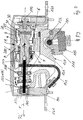
- FIG. 7 shows, by way of example for the application of the invention, a vacuum switching device with the essential functional parts in a partial cross section, in which vacuum switching tubes of the type according to the invention can be used.
- This is an electromagnetic switching device with a magnetic drive with a magnetic core, which is not shown in more detail, and the armature and at least one vacuum interrupter with a fixed contact, as well as with a lifting rod in direct linear operative connection and a movable contact with the lifting rod and the armature in operative connection Switch rocker for converting the drive movement into a switching movement of the movable contact.
- the lifting rod is firmly connected at one end to the contact carrier carrying the movable contact and the contact carrier on the output side with the vacuum interrupter in a tube bearing slidably mounted with respect to the longitudinal axis of the lifting rod.
- the armature 110 is fastened to the armature receptacle 111 and fixed to the rocker switch 120 with the interposition of the damping bearings 122 by means of the bolt 113, specifically to the rocker receiving bearing 121 formed at one end of the rocker switch 120.
- the rocker switch 120 is in the rail support housing 140 or the drive housing, not shown, of the vacuum switching device 200 is pivotally mounted.
- the vacuum interrupter 1 is arranged, which has at one end the fixed contact 31 carrying fixed contact carrier 30, which is fastened by means of screw 170 to the connecting lug 160 and is fixed in the rail support housing 140.
- the vacuum interrupter 1 further comprises the movable contact carrier 20 with the movable contact 21, the movement of which in the direction of the arrow P2, P2 'is sealed off from the vacuum interrupter 1 by means of the metal bellows 4.
- the vacuum interrupter 1 On the output side, the vacuum interrupter 1 has the tube bearing 147, in which the contact carrier 20 is slidably mounted in the direction of switching movement.
- the lifting rod 150 fastened at the end of the contact carrier 20 is in a linear direct operative connection with the movable contact carrier 20 and thus with the movable contact 21 and is also guided through the tube bearing 147 in this fastening region.
- the lifting rod 150 is axially guided in the axle guide bearing 160, the axle guide bearing 160 being arranged in the region of the side wall of the rail support housing 140 and arranged there by means of screws 153 which run perpendicular to the longitudinal axis X of the lifting rod and the vacuum interrupter 1.
- the strand 141 leading to the connecting rail 161 is fastened to the lifting rod, in direct connection to the end of the movable contact carrier 20 and on the other side by means of a hexagon nut on the lifting rod 150.
- the rocker switch 120 engages with its fork end 123a, b on both sides of the lifting rod 150 between the two bearings 147 and 160 for transmitting the switching movement P1 of the rocker switch.
- the rocker switch 120 is moved by triggering a corresponding armature movement, see arrow P3
- the rocker switch 120 is pivoted from the starting position in accordance with FIG Arrow P2, for closing the contacts 21, 31 of the vacuum interrupter 1 is executed.
- the lifting rod moves in the direction of arrow P2 'and the contacts 21, 31 open.
- the vacuum interrupter 1 comprises the movable conductor 2 and the fixed conductor 3, each of which has a contact carrier 20, 30 with a contact piece 21 or 31 attached to the mutually facing front ends.
- the vacuum interrupter is formed by the metallic cover parts 5, 6 with the insulator 7 arranged between them.
- the movable conductor 2 is sealed off from the housing or cover 5 by means of a guide 41 and the bellows 4.
- the outside parts forming the vacuum interrupter chamber are connected to one another via solder joints 10, 12, 14, 15, and the bellows 4 is fixed at the other end to the movable conductor 2 via the solder joint 16.
- the contact pieces 21, 31 are also connected to the respective contact carriers 20 and 30 via connecting surfaces 11, 13, which are designed as solder joints.
- a closed vacuum interrupter chamber 100 is thus formed.
- the contact pieces 21, 31 are laterally surrounded by the cylindrical screen 8, which is soldered on the one hand to the cover 6 in the area of the fixed contacts and extends with its free end into the area of the insulator 7, in order in this way to radiate heat and condensing metal vapor to catch and drain the switching area and shield the metal vapor arc from the cover 6 and the insulator 7.
- the screen 8 is made of copper, which enables particularly good heat dissipation.
- a getter in the form of a getter ring 9 is arranged on the outside of the screen 8 near its free end. The getter ring 9 is also protected against the direct influence of the metal vapor, since it is attached to the shield 8 on the outside, see also FIG. 1.
- FIG. 2 shows a getter ring which is produced from a correspondingly wide band by connecting the band ends 91 by means of spot welding, laser welding or, for example, electron beam welding or riveting.
- the inside diameter of the band is denoted by Ig, the band thickness by d and the band width by b.
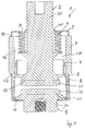
- the screen 8 is shown in perspective, which has a base screen part 81, with which it encompasses the area of the switch contacts, and adapted to this via a step-shaped shoulder 82, a cylindrical end area 83, which in turn tapers over a step-shaped shoulder 84 4, has a width a, which corresponds approximately to the thickness d of the getter ring, so that the getter ring 9 is seated thereon and is approximately flush with the outer surface 83 of the cylindrical screen.
- the height or remaining length Le of the cylindrical tapered end region 85 is somewhat larger than the width b of the getter ring 9 corresponds.
- FIG. 5 shows the getter ring 9 placed on the screen on the step-shaped shoulder 84, a narrow edge area of the dimension Le-b projecting beyond the getter ring 9 at the upper free end of the screen 8 and in this edge area, for example, by mechanical deformation four cramps 86a, 86b, 86c, 86d are formed by caulking outwards, by means of which the getter ring 9 is permanently fixed in the position pushed onto the screen 8 with the counter bearing of the step 84.
- This mechanical assembly according to the invention of the getter ring 9 on the screen 8 makes it possible to use a soft and not particularly weldable material for the screen 8, such as copper, which, however, has a high thermal conductivity.
- the attachment of the getter ring 9 placed on the screen 8 can be carried out in addition to the simple deformation by pressing the screen edge, or by partially or completely flanging the screen edge or the like.
- the cylindrical screen 8 also has a tapered cylindrical end region 85 over one step or two steps.
- the getter ring 9 is later pushed over this end region 85, as indicated, until it rests on the heel step.
- the tapered end region 85 is provided with three or more slots 8a, 8b, 8c which extend axially in the longitudinal extension of the screen 8. A greater height remains between the put-on getter ring 9 and the front end of the screen area 85, so that here sufficient flanging and overhanging, as shown in FIGS. 9 and 10, is made possible by bending outwards.
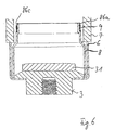
- FIG. 9 schematically shows how, after the getter ring 9 has been pulled onto the screen 8, the tapered screen area 85 is bent outwards, so to speak in a U-shape, and thereby a collar 88 is formed, the end 88a of which still spaced the getter ring 9 covered to the outside.
- the tapered area 85 from the step for supporting the getter ring so large that a a correspondingly wider, crimpable edge area remains.
- the flanging or bending is facilitated by the formation of the slots.
- the getter ring is preferably completely shaded by the collar formed in this way. In this way, an improved protection of the getter against coating with condensing metal vapor during the vacuum soldering phase and by vacuum arcs is provided.
- the flanged edge and collar 88 can also serve with its lower end 88a, if it is bent slightly outwards, as a means for centering the structure of the vacuum interrupter according to FIG. 1 by supporting the outer insulation 7, for example one Ceramic takes place and so that this ceramic 7 is centered with respect to the shield.
- the arrangement of the getter material on the outside of the shielding also protects it from the direct influence of the metal vapor arc and ensures that the getter functions at a high level over the long term.
- copper screens with high thermal conductivity can be used in connection with the getter.
- the attachment of the getter tape in the form of a prefabricated ring mechanically or by means of welded connections enables the getter material to be firmly connected to the copper screen.
- the getter ring can have any dimensions. Another advantageous fastening of the getter ring results from laser welding on the shield part, wherein shields made of heat-conducting materials, such as copper, copper alloys, can be used.
Landscapes
- High-Tension Arc-Extinguishing Switches Without Spraying Means (AREA)
- Driving Mechanisms And Operating Circuits Of Arc-Extinguishing High-Tension Switches (AREA)
- Keying Circuit Devices (AREA)
- Common Detailed Techniques For Electron Tubes Or Discharge Tubes (AREA)
- Compressors, Vaccum Pumps And Other Relevant Systems (AREA)
Priority Applications (2)
| Application Number | Priority Date | Filing Date | Title |
|---|---|---|---|
| CN 99103235 CN1123026C (zh) | 1998-03-31 | 1999-03-29 | 真空开关电子管的保护罩和保护罩的吸气剂固定方法 |
| JP11092474A JP2000057977A (ja) | 1998-03-31 | 1999-03-31 | 真空切換管のための遮蔽部材及び遮蔽部材にゲッタを固定するための方法 |
Applications Claiming Priority (2)
| Application Number | Priority Date | Filing Date | Title |
|---|---|---|---|
| DE19814398A DE19814398C1 (de) | 1998-03-31 | 1998-03-31 | Elektrisches Schaltgerät, insbesondere elektromagnetisches Schaltgerät mit Vakuumschaltröhre |
| DE19814398 | 1998-03-31 |
Publications (2)
| Publication Number | Publication Date |
|---|---|
| EP0955655A1 true EP0955655A1 (fr) | 1999-11-10 |
| EP0955655B1 EP0955655B1 (fr) | 2003-04-23 |
Family
ID=7863109
Family Applications (2)
| Application Number | Title | Priority Date | Filing Date |
|---|---|---|---|
| EP99101052A Expired - Lifetime EP0955655B1 (fr) | 1998-03-31 | 1999-01-22 | Blindage et gitter pour tube-interrupteur sous vide et procédé de fixation du gitter au blindage |
| EP99106099A Expired - Lifetime EP0949643B1 (fr) | 1998-03-31 | 1999-03-26 | Appareil de commutation électrique, notamment appareil de commutation électromagnétique avec interrupteur à vide |
Family Applications After (1)
| Application Number | Title | Priority Date | Filing Date |
|---|---|---|---|
| EP99106099A Expired - Lifetime EP0949643B1 (fr) | 1998-03-31 | 1999-03-26 | Appareil de commutation électrique, notamment appareil de commutation électromagnétique avec interrupteur à vide |
Country Status (3)
| Country | Link |
|---|---|
| EP (2) | EP0955655B1 (fr) |
| AT (1) | ATE241854T1 (fr) |
| DE (3) | DE19814398C1 (fr) |
Cited By (1)
| Publication number | Priority date | Publication date | Assignee | Title |
|---|---|---|---|---|
| DE20321632U1 (de) | 2003-05-21 | 2008-09-04 | Abb Ag | Getter für eine Vakuumschaltkammer |
Families Citing this family (3)
| Publication number | Priority date | Publication date | Assignee | Title |
|---|---|---|---|---|
| DE10238950B4 (de) * | 2002-08-24 | 2008-04-10 | Abb Patent Gmbh | Vakuumschaltgerät |
| DE102014212583A1 (de) * | 2014-06-30 | 2015-12-31 | Siemens Aktiengesellschaft | Vermeidung von Fehlausrichtungen einer Antriebsstange eines Leistungsschalters |
| CN110718415B (zh) * | 2018-07-12 | 2021-11-16 | 平高集团有限公司 | 一种真空断路器 |
Citations (2)
| Publication number | Priority date | Publication date | Assignee | Title |
|---|---|---|---|---|
| DE1185690B (de) * | 1963-05-15 | 1965-01-21 | Ass Elect Ind | Vakuumschalter |
| US4331850A (en) * | 1978-12-01 | 1982-05-25 | Hazemeijer B.V. | Vacuum switch including a getter device |
Family Cites Families (4)
| Publication number | Priority date | Publication date | Assignee | Title |
|---|---|---|---|---|
| US4032870A (en) * | 1975-09-15 | 1977-06-28 | General Electric Company | Electric circuit breaker with electromagnetic-assist means for opposing magnetic contact-separating forces |
| DE8905949U1 (de) * | 1989-05-11 | 1990-09-13 | Siemens AG, 1000 Berlin und 8000 München | Mehrpoliger Vakuum-Leistungsschalter mit einer isolierenden Traganordnung für die Schaltröhren |
| KR940000049Y1 (ko) * | 1991-12-13 | 1994-01-05 | 금성계전 주식회사 | 진공차단기의 아크방지용 개폐장치 |
| FR2737805B1 (fr) * | 1995-08-08 | 1997-08-29 | Gec Alsthom T & D Sa | Rupto-fusible sectionneur |
-
1998
- 1998-03-31 DE DE19814398A patent/DE19814398C1/de not_active Expired - Fee Related
-
1999
- 1999-01-22 DE DE59905131T patent/DE59905131D1/de not_active Expired - Fee Related
- 1999-01-22 EP EP99101052A patent/EP0955655B1/fr not_active Expired - Lifetime
- 1999-03-26 DE DE59905706T patent/DE59905706D1/de not_active Expired - Lifetime
- 1999-03-26 EP EP99106099A patent/EP0949643B1/fr not_active Expired - Lifetime
- 1999-03-26 AT AT99106099T patent/ATE241854T1/de not_active IP Right Cessation
Patent Citations (2)
| Publication number | Priority date | Publication date | Assignee | Title |
|---|---|---|---|---|
| DE1185690B (de) * | 1963-05-15 | 1965-01-21 | Ass Elect Ind | Vakuumschalter |
| US4331850A (en) * | 1978-12-01 | 1982-05-25 | Hazemeijer B.V. | Vacuum switch including a getter device |
Cited By (1)
| Publication number | Priority date | Publication date | Assignee | Title |
|---|---|---|---|---|
| DE20321632U1 (de) | 2003-05-21 | 2008-09-04 | Abb Ag | Getter für eine Vakuumschaltkammer |
Also Published As
| Publication number | Publication date |
|---|---|
| ATE241854T1 (de) | 2003-06-15 |
| EP0949643B1 (fr) | 2003-05-28 |
| DE19814398C1 (de) | 1999-12-30 |
| EP0955655B1 (fr) | 2003-04-23 |
| EP0949643A1 (fr) | 1999-10-13 |
| DE59905706D1 (de) | 2003-07-03 |
| DE59905131D1 (de) | 2003-05-28 |
Similar Documents
| Publication | Publication Date | Title |
|---|---|---|
| DE3586820T2 (de) | Magnetron mit einem keramiksockel versehen mit einer kathodenhalterungsvorrichtung. | |
| DE69730193T2 (de) | Spule mit axialem Magnetfeld für Vakuumschalter | |
| DE2557197C2 (de) | Vakuumschalter | |
| DE3709585A1 (de) | Vakuumgehaeuse fuer schaltkreisunterbrecher | |
| EP0955655B1 (fr) | Blindage et gitter pour tube-interrupteur sous vide et procédé de fixation du gitter au blindage | |
| EP1844486B1 (fr) | Procede de fabrication d'un element de contact et element de contact destine a une chambre de commutation a vide | |
| DE602005001955T2 (de) | Befestigungsvorrichtung für einen Schutzschirm in einem elektrischen Schalter, insbesondere einem Vakuumschalter. | |
| EP0660354B1 (fr) | Enveloppe pour interrupteur sous vide | |
| DE2536024A1 (de) | Hochspannungsvakuumschalter | |
| DE60101996T2 (de) | Vakuumschaltrohr | |
| DE2416747C3 (de) | Vakuumleistungsschalter | |
| EP0093414B1 (fr) | Tube interrupteur à vide | |
| DE10220110B4 (de) | Vakuumschaltkammer | |
| DE29901111U1 (de) | Abschirmung mit Getter für eine Vakuumschaltröhre | |
| DE1282768B (de) | Spulenanordnung zur Erzeugung eines Magnetfeldes in einem elektrischen Leistungsschalter | |
| DE2925307C2 (de) | Vakuum-Leistungsschalter | |
| DE3037752A1 (de) | Vakuumleistungsunterbrecherschalter | |
| DE69508680T2 (de) | Hochspannungsschalter | |
| DE4422316B4 (de) | Vakuumschaltröhre mit ringförmigem Isolator | |
| DE2758706A1 (de) | Mikrowellen-magnetron und verfahren zu seiner herstellung | |
| EP2140468B1 (fr) | Procédé de fixation d'un getter pour un interrupteur à vide et interrupteur à vide | |
| DE1915198B2 (de) | Vakuumschalter | |
| DE3411784A1 (de) | Kontakte fuer einen vakuumschalter | |
| DE102008026799A1 (de) | Vakuumschaltröhre | |
| DE3829888A1 (de) | Vakuum-schaltkammer |
Legal Events
| Date | Code | Title | Description |
|---|---|---|---|
| PUAI | Public reference made under article 153(3) epc to a published international application that has entered the european phase |
Free format text: ORIGINAL CODE: 0009012 |
|
| AK | Designated contracting states |
Kind code of ref document: A1 Designated state(s): DE FR GB |
|
| AX | Request for extension of the european patent |
Free format text: AL;LT;LV;MK;RO;SI |
|
| 17P | Request for examination filed |
Effective date: 19991228 |
|
| AKX | Designation fees paid |
Free format text: DE FR GB |
|
| GRAG | Despatch of communication of intention to grant |
Free format text: ORIGINAL CODE: EPIDOS AGRA |
|
| RTI1 | Title (correction) |
Free format text: SHIELDING AND GETTER FOR A VACUUM SWITCHING TUBE AND METHOD FOR FIXING OF THE GATTER TO THE SHIELDING |
|
| 17Q | First examination report despatched |
Effective date: 20020628 |
|
| GRAG | Despatch of communication of intention to grant |
Free format text: ORIGINAL CODE: EPIDOS AGRA |
|
| GRAH | Despatch of communication of intention to grant a patent |
Free format text: ORIGINAL CODE: EPIDOS IGRA |
|
| GRAH | Despatch of communication of intention to grant a patent |
Free format text: ORIGINAL CODE: EPIDOS IGRA |
|
| GRAA | (expected) grant |
Free format text: ORIGINAL CODE: 0009210 |
|
| AK | Designated contracting states |
Designated state(s): DE FR GB |
|
| REG | Reference to a national code |
Ref country code: GB Ref legal event code: FG4D Free format text: NOT ENGLISH |
|
| RIN1 | Information on inventor provided before grant (corrected) |
Inventor name: LIETZ, ALFREDO Inventor name: ROSSMANN, GERHARD Inventor name: LIPPERTS, JERRIE Inventor name: MEISSNER, JOHANNES, DR. |
|
| REF | Corresponds to: |
Ref document number: 59905131 Country of ref document: DE Date of ref document: 20030528 Kind code of ref document: P |
|
| GBT | Gb: translation of ep patent filed (gb section 77(6)(a)/1977) | ||
| ET | Fr: translation filed | ||
| PLBE | No opposition filed within time limit |
Free format text: ORIGINAL CODE: 0009261 |
|
| STAA | Information on the status of an ep patent application or granted ep patent |
Free format text: STATUS: NO OPPOSITION FILED WITHIN TIME LIMIT |
|
| 26N | No opposition filed |
Effective date: 20040126 |
|
| PGFP | Annual fee paid to national office [announced via postgrant information from national office to epo] |
Ref country code: DE Payment date: 20070110 Year of fee payment: 9 |
|
| PGFP | Annual fee paid to national office [announced via postgrant information from national office to epo] |
Ref country code: GB Payment date: 20070119 Year of fee payment: 9 |
|
| PGFP | Annual fee paid to national office [announced via postgrant information from national office to epo] |
Ref country code: FR Payment date: 20070111 Year of fee payment: 9 |
|
| GBPC | Gb: european patent ceased through non-payment of renewal fee |
Effective date: 20080122 |
|
| PG25 | Lapsed in a contracting state [announced via postgrant information from national office to epo] |
Ref country code: DE Free format text: LAPSE BECAUSE OF NON-PAYMENT OF DUE FEES Effective date: 20080801 |
|
| REG | Reference to a national code |
Ref country code: FR Ref legal event code: ST Effective date: 20081029 |
|
| PG25 | Lapsed in a contracting state [announced via postgrant information from national office to epo] |
Ref country code: GB Free format text: LAPSE BECAUSE OF NON-PAYMENT OF DUE FEES Effective date: 20080122 |
|
| PG25 | Lapsed in a contracting state [announced via postgrant information from national office to epo] |
Ref country code: FR Free format text: LAPSE BECAUSE OF NON-PAYMENT OF DUE FEES Effective date: 20080131 |