EP0955666B1 - Cathode de pulvérisation selon le principe magnétron - Google Patents
Cathode de pulvérisation selon le principe magnétron Download PDFInfo
- Publication number
- EP0955666B1 EP0955666B1 EP99105636A EP99105636A EP0955666B1 EP 0955666 B1 EP0955666 B1 EP 0955666B1 EP 99105636 A EP99105636 A EP 99105636A EP 99105636 A EP99105636 A EP 99105636A EP 0955666 B1 EP0955666 B1 EP 0955666B1
- Authority
- EP
- European Patent Office
- Prior art keywords
- target
- sources
- sputtering cathode
- permanent magnets
- axes
- Prior art date
- Legal status (The legal status is an assumption and is not a legal conclusion. Google has not performed a legal analysis and makes no representation as to the accuracy of the status listed.)
- Expired - Lifetime
Links
- 238000004544 sputter deposition Methods 0.000 title claims description 10
- 239000000463 material Substances 0.000 claims description 5
- 239000000696 magnetic material Substances 0.000 claims description 3
- 238000005477 sputtering target Methods 0.000 description 6
- 230000005415 magnetization Effects 0.000 description 4
- 239000000758 substrate Substances 0.000 description 3
- 239000011248 coating agent Substances 0.000 description 2
- 238000000576 coating method Methods 0.000 description 2
- 239000013077 target material Substances 0.000 description 2
- 230000006978 adaptation Effects 0.000 description 1
- 238000011109 contamination Methods 0.000 description 1
Images
Classifications
-
- H—ELECTRICITY
- H01—ELECTRIC ELEMENTS
- H01J—ELECTRIC DISCHARGE TUBES OR DISCHARGE LAMPS
- H01J23/00—Details of transit-time tubes of the types covered by group H01J25/00
- H01J23/02—Electrodes; Magnetic control means; Screens
- H01J23/04—Cathodes
- H01J23/05—Cathodes having a cylindrical emissive surface, e.g. cathodes for magnetrons
-
- C—CHEMISTRY; METALLURGY
- C04—CEMENTS; CONCRETE; ARTIFICIAL STONE; CERAMICS; REFRACTORIES
- C04B—LIME, MAGNESIA; SLAG; CEMENTS; COMPOSITIONS THEREOF, e.g. MORTARS, CONCRETE OR LIKE BUILDING MATERIALS; ARTIFICIAL STONE; CERAMICS; REFRACTORIES; TREATMENT OF NATURAL STONE
- C04B30/00—Compositions for artificial stone, not containing binders
- C04B30/02—Compositions for artificial stone, not containing binders containing fibrous materials
-
- H—ELECTRICITY
- H01—ELECTRIC ELEMENTS
- H01J—ELECTRIC DISCHARGE TUBES OR DISCHARGE LAMPS
- H01J37/00—Discharge tubes with provision for introducing objects or material to be exposed to the discharge, e.g. for the purpose of examination or processing thereof
- H01J37/32—Gas-filled discharge tubes
- H01J37/34—Gas-filled discharge tubes operating with cathodic sputtering
- H01J37/3402—Gas-filled discharge tubes operating with cathodic sputtering using supplementary magnetic fields
- H01J37/3405—Magnetron sputtering
- H01J37/3408—Planar magnetron sputtering
-
- C—CHEMISTRY; METALLURGY
- C04—CEMENTS; CONCRETE; ARTIFICIAL STONE; CERAMICS; REFRACTORIES
- C04B—LIME, MAGNESIA; SLAG; CEMENTS; COMPOSITIONS THEREOF, e.g. MORTARS, CONCRETE OR LIKE BUILDING MATERIALS; ARTIFICIAL STONE; CERAMICS; REFRACTORIES; TREATMENT OF NATURAL STONE
- C04B2111/00—Mortars, concrete or artificial stone or mixtures to prepare them, characterised by specific function, property or use
- C04B2111/54—Substitutes for natural stone, artistic materials or the like
Definitions
- the invention relates to a sputtering cathode according to the magnetron principle with a consisting of at least a part target from the material to be sputtered with a magnet arranged behind the target with sources of different polarity, is formed by the at least one self-contained tunnel of arcuately curved field lines, wherein the poles of the sources facing away from the target are connected to each other via a magnet yoke of soft magnetic material.
- a sputtering cathode (US Pat. No. 4,461,688) having a plate-shaped target and a plurality of U-shaped magnet units arranged on the side facing away from the substrate is known, the two legs of a first U-shaped magnet unit having its end faces facing away from the edge parts Abut surface of the target and abut another pair of U-shaped magnet units each at one half of the remote target surface with the end faces of their legs and further second pairs of smaller U-shaped magnet units with the faces of their two legs respectively on the outer half of the second A pair of magnetic units overlapped portion of the opposite surface of the target abut.
- a coverage of the targets on their base plate holding Pratzelfn be avoided with coating material to prevent the arcing and contamination of the substrates by chipping layer material.
- a preferred embodiment is defined in claim 2.
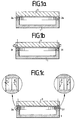
- Fig. 1a shows a conventional Sputterkathoden initial in cross section, consisting of the sputtering target with Jokkenplatte 3, the permanent magnet 2a and 2b and a yoke of soft magnetic material 1 for the magnetic yoke.
- the magnetization axes of the permanent magnets are opposite in parallel in the vertical direction, as indicated by arrows in FIG. 1a.
- An improved utilization of the target material can be achieved if the magnetization axes of the permanent magnets 2c and 2d are rotated by an angle ⁇ against the vertical axis, as shown in Fig. 1b.
- the respective optimum rotation angle ⁇ depends on the nature (eg material thickness) of the sputtering target 3 and has a direction of rotation relative to the vertical axis such that the lengths of the magnetic lines of force in or above the sputtering target are increased.
- the absolute amounts of the angles of rotation are equal for symmetry reasons for both magnets of the sputtering cathode (mirror symmetry to the cathode central axis).
- a further improvement in the utilization of the target material can be achieved if the permanent magnets 2a, 2b or 2c, 2d are replaced by two permanent magnets of half cross-sectional area 2e and 2f, as shown in FIG. 1c.
- two different angles of rotation ⁇ and ⁇ of the axes of magnetization are provided, the optimum angles of rotation depending on the nature of the sputtering target. Doubling the number of rotation angles results in advantages in the respective adaptation of the magnetic field to the sputtering target.
- the direction of rotation of both angles of rotation relative to the vertical axis is to be chosen so that the lengths of the magnetic lines of force in or over the sputtering target are increased, similar to that of the device according to FIG. 1b.
- the absolute amounts of two mirror-symmetrically opposite to the central axis of the sputtering cathode permanent magnets are the same for reasons of symmetry.
Landscapes
- Chemical & Material Sciences (AREA)
- Engineering & Computer Science (AREA)
- Ceramic Engineering (AREA)
- Physics & Mathematics (AREA)
- Plasma & Fusion (AREA)
- Analytical Chemistry (AREA)
- Materials Engineering (AREA)
- Structural Engineering (AREA)
- Organic Chemistry (AREA)
- Physical Vapour Deposition (AREA)
Claims (2)
- Cathode de pulvérisation selon le principe du magnétron comprenant une cible (3) composée au moins en partie du matériau à pulvériser, un système magnétique, disposé derrière la cible, comprenant des sources (2a à 2f) de polarité différente, par l'intermédiaire desquelles au moins un tunnel fermé en soi est formé par des lignes de champs courbées en arc, dans laquelle les aimants permanents formant les sources des champs magnétiques sont des prismes droits, de préférence des parallélépipèdes, dont les arêtes de base sont parallèles au plan de la cible, et les pôles des sources qui sont éloignés de la cible sont reliés entre eux par l'intermédiaire d'une culasse magnétique (1) faite d'un matériau magnétique doux, caractérisée en ce que les axes de magnétisation des sources sont chacun tournés selon un certain angle (α, β, γ) par rapport à un axe vertical aux surfaces des aimants permanents.
- Cathode de pulvérisation selon la revendication 1, caractérisée en ce que chaque source est composée d'au moins deux aimants permanents (2e, 2f) dont les axes de magnétisation présentent différents angles de rotation (β, γ).
Applications Claiming Priority (2)
| Application Number | Priority Date | Filing Date | Title |
|---|---|---|---|
| DE19819785A DE19819785A1 (de) | 1998-05-04 | 1998-05-04 | Zerstäubungskathode nach dem Magnetron-Prinzip |
| DE19819785 | 1998-05-04 |
Publications (2)
| Publication Number | Publication Date |
|---|---|
| EP0955666A1 EP0955666A1 (fr) | 1999-11-10 |
| EP0955666B1 true EP0955666B1 (fr) | 2007-03-07 |
Family
ID=7866581
Family Applications (1)
| Application Number | Title | Priority Date | Filing Date |
|---|---|---|---|
| EP99105636A Expired - Lifetime EP0955666B1 (fr) | 1998-05-04 | 1999-03-19 | Cathode de pulvérisation selon le principe magnétron |
Country Status (7)
| Country | Link |
|---|---|
| US (1) | US6077407A (fr) |
| EP (1) | EP0955666B1 (fr) |
| JP (1) | JP2000001779A (fr) |
| KR (1) | KR100359901B1 (fr) |
| DE (2) | DE19819785A1 (fr) |
| ES (1) | ES2284223T3 (fr) |
| TW (1) | TW439088B (fr) |
Families Citing this family (8)
| Publication number | Priority date | Publication date | Assignee | Title |
|---|---|---|---|---|
| DE19836125C2 (de) | 1998-08-10 | 2001-12-06 | Leybold Systems Gmbh | Zerstäubungsvorrichtung mit einer Kathode mit Permanentmagnetanordnung |
| US20020046945A1 (en) * | 1999-10-28 | 2002-04-25 | Applied Materials, Inc. | High performance magnetron for DC sputtering systems |
| US6887356B2 (en) * | 2000-11-27 | 2005-05-03 | Cabot Corporation | Hollow cathode target and methods of making same |
| DE10234858A1 (de) * | 2002-07-31 | 2004-02-12 | Fraunhofer-Gesellschaft zur Förderung der angewandten Forschung e.V. | Einrichtung zur Erzeugung einer Magnetron-Entladung |
| KR20140102696A (ko) * | 2011-12-27 | 2014-08-22 | 코니카 미놀타 가부시키가이샤 | 연마재 분리 방법 및 재생 연마재 |
| US10371244B2 (en) | 2015-04-09 | 2019-08-06 | United Technologies Corporation | Additive manufactured gear for a geared architecture gas turbine engine |
| EP3091101B1 (fr) | 2015-05-06 | 2018-10-17 | safematic GmbH | Unité de revêtement |
| EP3091561B1 (fr) | 2015-05-06 | 2019-09-04 | safematic GmbH | Unité de pulvérisation |
Family Cites Families (14)
| Publication number | Priority date | Publication date | Assignee | Title |
|---|---|---|---|---|
| US4265729A (en) * | 1978-09-27 | 1981-05-05 | Vac-Tec Systems, Inc. | Magnetically enhanced sputtering device |
| US4162954A (en) * | 1978-08-21 | 1979-07-31 | Vac-Tec Systems, Inc. | Planar magnetron sputtering device |
| US4180450A (en) * | 1978-08-21 | 1979-12-25 | Vac-Tec Systems, Inc. | Planar magnetron sputtering device |
| GB2028377B (en) * | 1978-08-21 | 1982-12-08 | Vac Tec Syst | Magnetically-enhanced sputtering device |
| US4239611A (en) * | 1979-06-11 | 1980-12-16 | Vac-Tec Systems, Inc. | Magnetron sputtering devices |
| US4461688A (en) * | 1980-06-23 | 1984-07-24 | Vac-Tec Systems, Inc. | Magnetically enhanced sputtering device having a plurality of magnetic field sources including improved plasma trapping device and method |
| CH648690A5 (de) * | 1980-10-14 | 1985-03-29 | Balzers Hochvakuum | Kathodenanordnung zur abstaeubung von material von einem target in einer kathodenzerstaeubungsanlage. |
| US4904362A (en) * | 1987-07-24 | 1990-02-27 | Miba Gleitlager Aktiengesellschaft | Bar-shaped magnetron or sputter cathode arrangement |
| DE3738845A1 (de) * | 1987-11-16 | 1989-05-24 | Leybold Ag | Zerstaeubungskatode nach dem magnetronprinzip |
| US4865708A (en) * | 1988-11-14 | 1989-09-12 | Vac-Tec Systems, Inc. | Magnetron sputtering cathode |
| US5162954A (en) * | 1990-07-31 | 1992-11-10 | Seagate Technology Inc. | Apparatus for generating an index pulse in a data storage system |
| DE4025077A1 (de) * | 1990-08-08 | 1992-02-20 | Leybold Ag | Magnetronkathode |
| US5262030A (en) * | 1992-01-15 | 1993-11-16 | Alum Rock Technology | Magnetron sputtering cathode with electrically variable source size and location for coating multiple substrates |
| US5399253A (en) * | 1992-12-23 | 1995-03-21 | Balzers Aktiengesellschaft | Plasma generating device |
-
1998
- 1998-05-04 DE DE19819785A patent/DE19819785A1/de not_active Withdrawn
-
1999
- 1999-03-19 ES ES99105636T patent/ES2284223T3/es not_active Expired - Lifetime
- 1999-03-19 EP EP99105636A patent/EP0955666B1/fr not_active Expired - Lifetime
- 1999-03-19 DE DE59914230T patent/DE59914230D1/de not_active Expired - Lifetime
- 1999-04-03 TW TW088105378A patent/TW439088B/zh not_active IP Right Cessation
- 1999-04-29 US US09/301,459 patent/US6077407A/en not_active Expired - Lifetime
- 1999-04-30 JP JP11125080A patent/JP2000001779A/ja active Pending
- 1999-05-03 KR KR1019990015825A patent/KR100359901B1/ko not_active Expired - Lifetime
Also Published As
| Publication number | Publication date |
|---|---|
| DE59914230D1 (de) | 2007-04-19 |
| JP2000001779A (ja) | 2000-01-07 |
| DE19819785A1 (de) | 1999-11-11 |
| KR100359901B1 (ko) | 2002-11-04 |
| TW439088B (en) | 2001-06-07 |
| KR19990088019A (ko) | 1999-12-27 |
| EP0955666A1 (fr) | 1999-11-10 |
| US6077407A (en) | 2000-06-20 |
| ES2284223T3 (es) | 2007-11-01 |
Similar Documents
| Publication | Publication Date | Title |
|---|---|---|
| DE60208204T2 (de) | Statorkern für ein Magnetlager | |
| DE69715605T2 (de) | Magnetisches leistungsubertragungssystem | |
| DE102015115347A1 (de) | Magnetanordnung für einen elektrischen Motor | |
| DE112013005732B4 (de) | Sputtergerät und Substratbearbeitungsgerät | |
| CH648690A5 (de) | Kathodenanordnung zur abstaeubung von material von einem target in einer kathodenzerstaeubungsanlage. | |
| DE69404483T2 (de) | Permanentmagnet-Vorrichtung zur Verwendung in Magnetron-Plasma-Prozessen | |
| DE4126137C2 (fr) | ||
| EP0955666A1 (fr) | Cathode de pulvérisation selon le principe magnétron | |
| WO2000002702A1 (fr) | Procede pour maintenir des composants constitues d'un materiau ferromagnetique | |
| EP1722005B1 (fr) | Méthode pour l'utilisation d'une cathode de pulvérisation ayant une cible | |
| DE69926561T2 (de) | Elektromotor | |
| DE2828844A1 (de) | Vorrichtung zum beidseitigen bestrahlen eines targets mittels eines beschleunigers fuer geladene teilchen | |
| EP1255120A3 (fr) | Appareil de résonance magnétique avec un système ouvert d'aimant et un agencement de bobines en quadrature | |
| EP1723713A1 (fr) | Dispositif d'entrainement lineaire pourvu d'un corps d'induit comportant un porte-aimant | |
| DE3029380C2 (fr) | ||
| EP0980090B1 (fr) | Dispositif de pulvérisation avec une cathode comportant un assemblage d'aimants permanents | |
| WO1995002459A1 (fr) | Systeme magnetique de separation de particules | |
| DE2548243A1 (de) | Vorrichtung zum bearbeiten von blechmaterialien | |
| DE19811073C2 (de) | Zylindrischer, mehrphasiger Transversalflußaktor | |
| DE19826935C2 (de) | Optischer Durchlicht-Strahlablenker | |
| DE2617939C2 (de) | Magnetischer Rollgang | |
| DE20115258U1 (de) | Polplattenstruktur für den Stator eines Motors | |
| DE102019113092A1 (de) | Sputterkathode-Magnetsystem und Vakuumanordnung | |
| DE60315398T2 (de) | Flacher Schrittmotor mit zwei horizontal nebeneinanderliegenden Spulen | |
| DE102011080008A1 (de) | Elektrische Maschine |
Legal Events
| Date | Code | Title | Description |
|---|---|---|---|
| PUAI | Public reference made under article 153(3) epc to a published international application that has entered the european phase |
Free format text: ORIGINAL CODE: 0009012 |
|
| AK | Designated contracting states |
Kind code of ref document: A1 Designated state(s): BE DE ES FR GB LU NL |
|
| AX | Request for extension of the european patent |
Free format text: AL;LT;LV;MK;RO;SI |
|
| 17P | Request for examination filed |
Effective date: 20000408 |
|
| AKX | Designation fees paid |
Free format text: BE DE ES FR GB LU NL |
|
| RAP1 | Party data changed (applicant data changed or rights of an application transferred) |
Owner name: APPLIED FILMS GMBH & CO. KG |
|
| 17Q | First examination report despatched |
Effective date: 20050315 |
|
| GRAP | Despatch of communication of intention to grant a patent |
Free format text: ORIGINAL CODE: EPIDOSNIGR1 |
|
| RAP1 | Party data changed (applicant data changed or rights of an application transferred) |
Owner name: APPLIED MATERIALS GMBH & CO. KG |
|
| GRAS | Grant fee paid |
Free format text: ORIGINAL CODE: EPIDOSNIGR3 |
|
| GRAA | (expected) grant |
Free format text: ORIGINAL CODE: 0009210 |
|
| AK | Designated contracting states |
Kind code of ref document: B1 Designated state(s): BE DE ES FR GB LU NL |
|
| REG | Reference to a national code |
Ref country code: GB Ref legal event code: FG4D Free format text: NOT ENGLISH |
|
| REF | Corresponds to: |
Ref document number: 59914230 Country of ref document: DE Date of ref document: 20070419 Kind code of ref document: P |
|
| GBT | Gb: translation of ep patent filed (gb section 77(6)(a)/1977) |
Effective date: 20070614 |
|
| REG | Reference to a national code |
Ref country code: ES Ref legal event code: FG2A Ref document number: 2284223 Country of ref document: ES Kind code of ref document: T3 |
|
| PLBE | No opposition filed within time limit |
Free format text: ORIGINAL CODE: 0009261 |
|
| STAA | Information on the status of an ep patent application or granted ep patent |
Free format text: STATUS: NO OPPOSITION FILED WITHIN TIME LIMIT |
|
| 26N | No opposition filed |
Effective date: 20071210 |
|
| REG | Reference to a national code |
Ref country code: DE Ref legal event code: R082 Ref document number: 59914230 Country of ref document: DE Representative=s name: ZIMMERMANN & PARTNER PATENTANWAELTE MBB, DE Ref country code: DE Ref legal event code: R082 Ref document number: 59914230 Country of ref document: DE Representative=s name: ZIMMERMANN & PARTNER, DE |
|
| REG | Reference to a national code |
Ref country code: FR Ref legal event code: PLFP Year of fee payment: 17 |
|
| REG | Reference to a national code |
Ref country code: FR Ref legal event code: PLFP Year of fee payment: 18 |
|
| REG | Reference to a national code |
Ref country code: FR Ref legal event code: PLFP Year of fee payment: 19 |
|
| REG | Reference to a national code |
Ref country code: FR Ref legal event code: PLFP Year of fee payment: 20 |
|
| PGFP | Annual fee paid to national office [announced via postgrant information from national office to epo] |
Ref country code: LU Payment date: 20180321 Year of fee payment: 20 Ref country code: DE Payment date: 20180322 Year of fee payment: 20 Ref country code: GB Payment date: 20180321 Year of fee payment: 20 Ref country code: NL Payment date: 20180321 Year of fee payment: 20 |
|
| PGFP | Annual fee paid to national office [announced via postgrant information from national office to epo] |
Ref country code: FR Payment date: 20180323 Year of fee payment: 20 Ref country code: BE Payment date: 20180321 Year of fee payment: 20 |
|
| PGFP | Annual fee paid to national office [announced via postgrant information from national office to epo] |
Ref country code: ES Payment date: 20180427 Year of fee payment: 20 |
|
| REG | Reference to a national code |
Ref country code: DE Ref legal event code: R071 Ref document number: 59914230 Country of ref document: DE |
|
| REG | Reference to a national code |
Ref country code: NL Ref legal event code: MK Effective date: 20190318 |
|
| REG | Reference to a national code |
Ref country code: GB Ref legal event code: PE20 Expiry date: 20190318 |
|
| PG25 | Lapsed in a contracting state [announced via postgrant information from national office to epo] |
Ref country code: GB Free format text: LAPSE BECAUSE OF EXPIRATION OF PROTECTION Effective date: 20190318 |
|
| REG | Reference to a national code |
Ref country code: BE Ref legal event code: MK Effective date: 20190319 |
|
| REG | Reference to a national code |
Ref country code: ES Ref legal event code: FD2A Effective date: 20200724 |
|
| PG25 | Lapsed in a contracting state [announced via postgrant information from national office to epo] |
Ref country code: ES Free format text: LAPSE BECAUSE OF EXPIRATION OF PROTECTION Effective date: 20190320 |