EP0955772A2 - Appareil de reproduction de signal vidéo et appareil de visualisation de signal vidéo - Google Patents
Appareil de reproduction de signal vidéo et appareil de visualisation de signal vidéo Download PDFInfo
- Publication number
- EP0955772A2 EP0955772A2 EP99303563A EP99303563A EP0955772A2 EP 0955772 A2 EP0955772 A2 EP 0955772A2 EP 99303563 A EP99303563 A EP 99303563A EP 99303563 A EP99303563 A EP 99303563A EP 0955772 A2 EP0955772 A2 EP 0955772A2
- Authority
- EP
- European Patent Office
- Prior art keywords
- video signal
- liquid crystal
- brightness
- crystal display
- display circuit
- Prior art date
- Legal status (The legal status is an assumption and is not a legal conclusion. Google has not performed a legal analysis and makes no representation as to the accuracy of the status listed.)
- Withdrawn
Links
Images


Classifications
-
- H—ELECTRICITY
- H04—ELECTRIC COMMUNICATION TECHNIQUE
- H04N—PICTORIAL COMMUNICATION, e.g. TELEVISION
- H04N5/00—Details of television systems
- H04N5/76—Television signal recording
- H04N5/78—Television signal recording using magnetic recording
- H04N5/782—Television signal recording using magnetic recording on tape
- H04N5/783—Adaptations for reproducing at a rate different from the recording rate
-
- Y—GENERAL TAGGING OF NEW TECHNOLOGICAL DEVELOPMENTS; GENERAL TAGGING OF CROSS-SECTIONAL TECHNOLOGIES SPANNING OVER SEVERAL SECTIONS OF THE IPC; TECHNICAL SUBJECTS COVERED BY FORMER USPC CROSS-REFERENCE ART COLLECTIONS [XRACs] AND DIGESTS
- Y10—TECHNICAL SUBJECTS COVERED BY FORMER USPC
- Y10S—TECHNICAL SUBJECTS COVERED BY FORMER USPC CROSS-REFERENCE ART COLLECTIONS [XRACs] AND DIGESTS
- Y10S358/00—Facsimile and static presentation processing
- Y10S358/906—Hand-held camera with recorder in a single unit
Definitions
- the present invention relates to a video signal reproducing apparatus comprising a display means for displaying a reproduced video signal, and a video signal display apparatus, and more particularly to such apparatus suitable for displaying a video image on a liquid crystal display means.
- a helical scan type video signal reproducing apparatus generally reproduces a signal with at least two magnetic heads (hereinafter referred to as “CH1 head” and “CH2 head”) mounted on a rotary drum and having different azimuth angles.
- a magnetic tape has oblique tracks on which a video signal is recorded. The oblique tracks are alternately formed by the respective magnetic heads at azimuth angles equal to those of the corresponding magnetic heads.
- n an integer
- n is an integer
- the display operation utilizes the opposite phase relationship between reproduced signals of the respective magnetic heads.
- the amount of polarization of liquid crystal is gradually attenuated during a period in which the video signal is not written. For this reason, with a liquid crystal display means having a back light function, light from a back light source more easily transmits the liquid crystal. Likewise, with a liquid crystal display means having a reflector, reflected light more easily transmits the liquid crystal. In other words, this means that a displayed video image changes in a brighter direction.
- This phenomenon constitutes a problem which arises not only in the liquid crystal display means but also similarly in a video display means which displays a video image while accumulating the level of the video signal in analog amount.
- a displayed video image may change in a brighter or darker direction depending on the characteristics of a particular video display means.
- the present invention has taken the following measures.
- a video signal reproducing apparatus is a helical scan type video signal reproducing apparatus for reproducing a video signal from a magnetic tape wrapped around a rotary drum having magnetic heads mounted thereon.
- the apparatus comprises a tape driving controller for controlling driving of the magnetic tape, a reproduced signal processing circuit for processing output signals from the magnetic heads to generate a reproduced video signal, a liquid crystal display circuit for displaying the reproduced video signal, a write controller for writing the reproduced video signal into the liquid crystal display circuit, and a brightness controller for controlling the brightness for the liquid crystal display circuit.
- the brightness controller controls the liquid crystal display circuit to display a brighter image thereon when the write controller continuously writes the reproduced video signal into the liquid crystal display circuit, while the brightness controller controls the liquid crystal display circuit to display a darker image thereon when the write controller discontinuously writes the reproduced video signal into the liquid crystal display circuit.
- the write controller discontinuously writes a reproduced video signal into the liquid crystal display circuit when the magnetic heads each scan the oblique tracks on the magnetic tape at an oblique angle different from the oblique angles of the oblique tracks, and the tape driving controller controls driving of the magnetic tape such that envelope of signals reproduced from the plurality of magnetic heads is in an alternately opposite phase relationship.
- the write controller writes the reproduced video signal into the liquid crystal display circuit during a period in which the magnetic heads reproduce tracks with the same azimuth angles, and the write controller controls to stop writing the reproduced video signal into the liquid crystal display circuit during a period in which the magnetic heads reproduce tracks with different azimuth angles.
- the video signal reproducing apparatus further comprises a reference brightness register for supplying the brightness controller with reference brightness.
- the brightness controller controls the brightness for the liquid crystal display circuit based on the reference brightness when the write controller continuously writes a reproduced video signal into the liquid crystal display circuit, and the brightness controller controls the liquid crystal display circuit to display an image of brightness lower than the reference brightness when the write controller discontinuously writes a reproduced video signal into the liquid crystal display circuit.
- an input terminal is provided for the user to set the reference brightness supplied by the reference brightness register.
- the brightness of a displayed video image is controlled at brightness set by the user himself in either of a mode in which a video signal is continuously written and a mode in which a video signal is discontinuously written, thereby making it possible to provide the user with more consistent images on the liquid crystal display circuit.
- the brightness controller may be an amplitude controller for controlling the amplitude of a video signal written into a liquid crystal matrix circuit (brightness controller) or a controller for controlling the center of control in the liquid crystal matrix circuit of a video signal written into the liquid crystal matrix circuit (contrast controller).
- Another video signal reproducing apparatus is a helical scan type video signal reproducing apparatus which comprises a tape driving controller, a reproduced signal processing circuit, a liquid crystal display circuit, and a brightness controller for controlling the brightness for the liquid crystal display circuit.
- the brightness controller controls the liquid crystal display circuit to display a darker image thereon when the tape driving controller controls the magnetic tape to run at a velocity even-number times (the even-number may be zero) as high as a velocity at which a video signal was recorded on the magnetic tape.
- the brightness controller controls the liquid crystal display circuit to display a brighter image thereon when the tape driving controller controls the magnetic tape to run at a velocity odd-number times as high as a velocity at which a video signal was recorded on the magnetic tape.
- a video display apparatus comprises a liquid crystal display circuit, a write controller, and a brightness controller for controlling the brightness for the liquid crystal display circuit.
- the brightness controller controls the liquid crystal display circuit to display a brighter image thereon when the write controller continuously writes a video signal into the liquid crystal display circuit, and the brightness controller controls the liquid crystal display circuit to display a darker image thereon when the write controller discontinuously writes a video signal into the liquid crystal display circuit.
- Another video display apparatus comprises a display device, having a memory effect, for displaying a video signal, a write controller, and a brightness controller for controlling the brightness for the display device.
- the brightness controller controls the display device to display a brighter video image thereon when the write controller continuously writes a reproduced video signal into the display device, and the brightness controller controls the display device to display a darker video image thereon when the write controller discontinuously writes a reproduced video signal into the display device.
- the brightness controller controls the display device to display a darker image thereon when the write controller continuously writes a reproduced video signal into the display device, and the brightness controller controls the display device to display a brighter image thereon when the write controller discontinuously writes a reproduced video signal into the display device.
- a mechanical system comprises a magnetic tape 1; a rotary drum 2 having magnetic heads 4, 5 mounted thereon; a drum motor 3 for rotating the rotary drum 2; a capstan shaft 6; a pinch roller 7; and a capstan motor 8.
- a signal processing system comprises a head switch 9 for switching signals from the magnetic heads 4, 5; a preamplifier 10 for amplifying output signals of the magnetic heads 4, 5; a reproduced video signal processing circuit 11 for modulating and equalizing an output signal from the preamplifier 10 to recover a reproduced video signal; an envelope signal detector circuit 12 for detecting an amplitude component of the output signal from the preamplifier 10; and a liquid crystal display circuit 21.
- a motor control system 24 in turn comprises a drum motor servo controller circuit 13 for controlling the rotational speed and phase of the drum motor 3 in response to a rectangular wave signal at a frequency proportional to the rotating frequency of the drum motor 3 (hereinafter referred to as the "DFG (Drum Frequency Generator) signal”) and a signal indicative of the rotating phase of the drum motor 3 (hereinafter referred to as the “DPG (Drum Phase Generator) signal”); a head switch signal generator circuit 14 for generating switching timing for the heads 4, 5 from the DPG signal or the DFG signal referenced by the DPG signal; a power amplifier circuit 15 for producing electric power for driving the drum motor 3 and a driver circuit 16 for driving a multi-phase motor; a capstan servo control processing circuit 17 for controlling the tape running speed and phase from a rectangular wave signal at a frequency proportional to the rotating frequency of the capstan motor 8 (hereinafter referred to as the "CFG (Capstan Frequency Generator) signal”) and a tape running phase error signal; a write hold
- the video signal reproducing apparatus further comprises a system controller 22 for giving a variety of operation instructions to the entire system and a reference brightness register 23 for storing a control value for the brightness of the liquid crystal display circuit 21, which may be set by the user.
- the drum motor servo controller circuit 13 in turn generates a control signal for maintaining the period of the DFG signal constant, and controls the rotation phase with respect to the tape 1 through the DPG signal. In this way, the drum motor 3 is controlled with respect to the speed and phase.
- the capstan servo control processing circuit 17 generates a velocity control signal for maintaining the period of the CFG signal constant.
- the capstan motor 8 is controlled to transport the tape 1 at a velocity substantially even-number times higher than the velocity at which the tape 1 was recorded. Then, a phase control signal for the capstan motor 8 is generated in the following manner.
- the envelope signal detector circuit 12 detects amplitude components of signals read from the tape 1, and inputs the detected signal to the AD converter circuit 19. Assuming that the tape 1 is controlled to run at a velocity substantially four times higher than the velocity at which the tape 1 was recorded, the output signal of the envelope signal detector circuit 12 and other signals at the respective circuit components in Fig. 1 are as illustrated in the waveform charts of Fig. 2. Specifically, Fig.
- FIG. 2 illustrates a switching signal 101 supplied to the head switch 9; an output signal 102 of the head switch 9; the output signal 103 of the envelope signal detector circuit 12; an output signal 104 of the write hold signal generator circuit 18; and sampling timing 105 of the AD converter circuit 19.
- each of the output signals 102 exhibits a maximum level when an associated head traverses a track having the same azimuth angle as the head, and a minimum level when the head traverses a track having a different azimuth angle.
- the signal 103 is derived by detecting the envelope of the output signals 102.
- the write hold signal generator circuit 18 multiplies the output signal of the head switch signal generator circuit 14 by substantially three (
- the capstan servo processing circuit 17 processes the difference between the sample values at the two sampling points as an error signal indicative of an error in tape running phase to control the tape running phase. As a result, the tape running phase is controlled such that a level of the envelope detection signal in the vicinity of a median point is synchronized with the rising and falling edges of the write hold timing signal.
- both of the two heads 4, 5 were used to individually sample the envelope signal 103 to calculate the difference, the respective heads 4, 5 might possibly calculate different phase error signals if the heads 4, 5 produced varying outputs. For this reason, only one of the heads is used to sample the envelope signal 103 for calculating the phase error. This results in stabilized switching timing of the write hold signal even if the outputs of the heads 4, 5 present variations.
- the capstan motor 8 is controlled with respect to the speed and phase.
- the write hold signal generator circuit 18 also generates a write hold signal for disabling/enabling update of data in the liquid crystal display circuit 21.
- the envelope detection signal and the write hold signal both exhibit an opposite phase relationship for the head 4 and the head 5.
- a lower level portion of the envelope detection signal i.e., a signal during a noise output period is prevented from being displayed on the screen.
- the drum motor 3 and the capstan motor 8 are driven by associated signals which have been amplified in power by the processing circuits 15, 16, respectively.
- the tape 1 is forced to stand still at a phase at which one of the heads 4, 5 delivers an increasing output and the other one delivers a decreasing output, as illustrated in Fig. 3.
- the system controller 22 instructs the capstan motor 8 to stop after the lapse of a predetermined time with reference to the phase of the head switch signal.
- the write hold signal generator circuit 18 generates a signal in phase with the head switch signal, for example, as illustrated in Fig. 3 and writes output signal of only one head into the liquid crystal display circuit 21, with the result that a noise-free still image can be displayed.
- the system controller 22 controls the write hold signal generator circuit 18 not to output the write hold timing signal to the liquid crystal display circuit 21 during reproduction at a velocity odd-number, including one, times higher than that during recording.
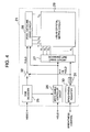
- the liquid crystal display circuit 21 comprises an RGB decoder 25; a write disable controller circuit 26; a scanning line drive circuit 27; a pixel data line drive circuit 28; a liquid crystal matrix circuit 29; a register 30 for storing a brightness control value sent thereto from the system controller 22; a digital-to-analog (DA) converter 31 for converting the control value to an analog signal; and an amplifier 32 for controlling the amplitude and operating point of a video signal to be written.
- RGB decoder 25 for storing a brightness control value sent thereto from the system controller 22
- DA digital-to-analog
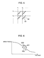
- Fig. 5 illustrates an example of the internal configuration of the matrix 29 of liquid crystal display pixels, each of which is composed of a liquid crystal element 34 and a diode 33 for preventing a video signal written into the liquid crystal element 34 from discharging.
- a reproduced video signal outputted from the reproduced signal processing circuit 11 is inputted to the RGB decoder 25 which recovers three primary colors from the reproduced video signal.
- the RGB decoder 22 also separates synchronization signals multiplexed on the video signal and inputs the same into the write disable controller circuit 26.
- the write disable controller circuit 26 separates from the synchronization signals a horizontal synchronization signal and a vertical synchronization signal, mainly required by the scanning line drive circuit 27; generates a dot clock, mainly required by the pixel data line drive circuit 28; and appropriately processes the write hold signal for disabling/enabling update of data and inputs the processed write hold signal to the respective drive circuits 27, 28.
- the respective drive circuits 27, 28, for giving respective gradation levels to respective pixels sequentially generate potential differences on horizontal lines and vertical lines illustrated in Fig. 5 to turn on only diodes of selected pixels so that the respective liquid crystal elements thus selected are applied with respective potential differences.
- update of data can be disabled only by preventing the drive circuits 27, 28 from generating the potential differences.
- a liquid crystal element changes the amount of polarized light when it is applied with a potential difference.
- a reflection type liquid crystal display circuit when light impinging on a reflector plate (not shown) disposed at the back of the liquid crystal matrix circuit 29 passes through the liquid crystal matrix circuit 29, a portion of which is applied with a potential difference to polarize the light and hence reduce the transmissivity, that portion becomes darker.
- a light source generally referred to as so-called "back light" (not shown) is disposed at the back of the liquid crystal matrix circuit 29.
- back light is disposed at the back of the liquid crystal matrix circuit 29.
- a video signal is sequentially written into each liquid crystal element at a field period or a frame period of the video signal.
- a video signal is written at a period double the period during reproduction at velocity odd-number times higher. Therefore, a video image displayed during the search at a velocity even-number times higher or during the still image reproduction becomes slightly brighter, as compared with the brightness of a video image displayed during reproduction at a velocity odd-number, including one, times higher, because of a longer discharge duration.
- the liquid crystal display circuit 21 is controlled for brightness in the following manner to suppress variations in brightness between a displayed video image reproduced at a velocity odd-number, including one, times higher and a displayed video image reproduced at a velocity even-number times higher or a reproduced still image, thereby allowing the user to have a less feeling of strangeness.
- the user gives an instruction to the system controller 22 in Fig. 1 through keys or the like (not shown) arranged on the apparatus in order to set appropriate brightness for a displayed video image in the liquid crystal display circuit 21 in accordance with a particular environment in which the apparatus is used.
- the system controller 22 increases the value in the reference brightness register 23 when an instruction is given to a "+" terminal in Fig. 1, and decreases the value in the reference brightness register 23 when an instruction is given to a "-" terminal.
- the system controller 22 reads the value in the reference brightness register 23 and sends the read value to the liquid crystal display circuit 21.
- the liquid crystal display circuit 21 receives and stores this value in the brightness register 30 in Fig. 4, and converts the value to an analog signal through the digital-to-analog converter 31.
- This analog signal causes the amplifier 32 to change the amplification ratio or an operation point to control a potential difference of a video signal that is written into the liquid crystal element 34 of the liquid crystal matrix circuit 29.
- the brightness may be changed by controlling potentials set to the scanning line drive circuit 27. In the manner described above, the user first controls the brightness of a desired video image displayed during reproduction at a velocity odd-number, including one, times higher.
- the system controller 22 upon receipt of a request from the user for the aforementioned search at a velocity even-number times higher or for trick reproduction of a still image, gives corresponding instructions to the respective components of the motor control system 24, causing the motor control system 24 to transition to a motor control target for the search. Also, the system controller 22 corrects a brightness control value based on the value in the reference brightness register 23 to make a displayed video image darker, and sends the brightness control value to the liquid crystal display circuit 21. In this way, the liquid crystal display circuit 21 receives the brightness control value for making the displayed image darker while the displayed video image inherently tends to be brighter during the search or during reproduction of a still image because of a longer write period for the liquid crystal elements.
- the cancellation of the displayed image tending to be brighter and the brightness control value intended for a darker displayed image results in reducing a change in brightness, viewed from the user, during reproduction at a velocity odd-number, including one, times higher and during the search at a velocity even-number times higher or during reproduction of a still image.
- the difference in brightness, viewed from the user, between an image reproduced at a velocity odd-number, including one, times higher and an image reproduced during the search at a velocity even-number times higher or a reproduced still image is previously set as a correction value for the brightness control value in the reference brightness register 23 associated with the system controller 22.
- the system controller 22 may monitor when discontinuous writing into the liquid crystal display circuit 21 is executed, relying on information from the motor control unit 24 on how the motors respond or from information on how the write hold timing signal generator circuit 18 outputs the write hold signal, and switch the brightness based on the discontinuous writing, if detected.
- a voltage across the terminals of a liquid crystal element may be illustrated in Fig. 6.
- the brightness may be controlled by reducing the amplitude of a written video signal through the amplifier 32 in Fig. 4 to restrict the brightness to a range indicated by reference numeral 201.
- the brightness control may be realized by increasing a voltage at the operation point of the amplifier 32 in Fig. 4 and a voltage applied to the scanning line drive circuit 27 to shift the brightness into a range indicated by reference numeral 203.
- a similar control scheme may be applied to any video display means as long as it has the ability of holding a video image to be displayed.
- a control scheme similar to the foregoing may be applied if the video display means has a characteristic of displaying a brighter video image as a write period is longer.
- a video display means which displays a darker video image as a write period is longer, a video image displayed during a search at a velocity even-number times higher or during still image reproduction may only be controlled to be brighter as compared with the brightness of a video image displayed during reproduction at a velocity odd-number, including one, times higher.
- the present invention can effectively suppress, with a simple configuration, the difference in brightness between a mode in which a video signal is continuously written into a display means and a mode in which a video signal is discontinuously written into the display means, the present invention can advantageously provide the user with a displayed video image free from a feeling of strangeness.
Landscapes
- Engineering & Computer Science (AREA)
- Multimedia (AREA)
- Signal Processing (AREA)
- Liquid Crystal Display Device Control (AREA)
- Television Signal Processing For Recording (AREA)
- Control Of Indicators Other Than Cathode Ray Tubes (AREA)
- Picture Signal Circuits (AREA)
- Television Receiver Circuits (AREA)
Applications Claiming Priority (2)
| Application Number | Priority Date | Filing Date | Title |
|---|---|---|---|
| JP12564098 | 1998-05-08 | ||
| JP10125640A JPH11331741A (ja) | 1998-05-08 | 1998-05-08 | 映像信号再生装置および映像信号表示装置 |
Publications (2)
| Publication Number | Publication Date |
|---|---|
| EP0955772A2 true EP0955772A2 (fr) | 1999-11-10 |
| EP0955772A3 EP0955772A3 (fr) | 2001-01-24 |
Family
ID=14915037
Family Applications (1)
| Application Number | Title | Priority Date | Filing Date |
|---|---|---|---|
| EP99303563A Withdrawn EP0955772A3 (fr) | 1998-05-08 | 1999-05-06 | Appareil de reproduction de signal vidéo et appareil de visualisation de signal vidéo |
Country Status (3)
| Country | Link |
|---|---|
| US (1) | US6504992B1 (fr) |
| EP (1) | EP0955772A3 (fr) |
| JP (1) | JPH11331741A (fr) |
Families Citing this family (1)
| Publication number | Priority date | Publication date | Assignee | Title |
|---|---|---|---|---|
| KR100839804B1 (ko) * | 2000-10-31 | 2008-06-19 | 코닌클리케 필립스 일렉트로닉스 엔.브이. | 이미지들을 디스플레이하는 시스템 및 방법 |
Family Cites Families (8)
| Publication number | Priority date | Publication date | Assignee | Title |
|---|---|---|---|---|
| US5155477A (en) * | 1988-11-18 | 1992-10-13 | Sony Corporation | Video signal display apparatus with a liquid crystal display unit |
| US5623344A (en) | 1992-09-01 | 1997-04-22 | Hitachi America, Ltd. | Digital video recording device with trick play capability |
| EP0630023B1 (fr) * | 1993-06-18 | 1999-05-19 | Matsushita Electric Industrial Co., Ltd. | Appareil d'enregistrement et de reproduction |
| KR0137333B1 (ko) * | 1994-06-24 | 1998-05-15 | 김광호 | 배속재생을 위한 헤드트래킹 제어방법 및 그 장치 |
| KR19980702009A (ko) * | 1995-12-05 | 1998-07-15 | 요트. 게아. 아 롤페즈 | 비디오 레코더 섹션과 텔레비젼 수상기 섹션을 포함하는 조합 장치 |
| JP3557817B2 (ja) * | 1996-11-07 | 2004-08-25 | ソニー株式会社 | 記録モード判別装置及び記録モード判別方法 |
| JP3423193B2 (ja) * | 1997-06-30 | 2003-07-07 | 三洋電機株式会社 | 液晶駆動回路 |
| US6278496B1 (en) * | 1997-10-09 | 2001-08-21 | Sanyo Electric Co., Ltd. | Digital correction circuit and image data processing apparatus equipped with a digital correction circuit |
-
1998
- 1998-05-08 JP JP10125640A patent/JPH11331741A/ja active Pending
-
1999
- 1999-05-06 US US09/305,451 patent/US6504992B1/en not_active Expired - Fee Related
- 1999-05-06 EP EP99303563A patent/EP0955772A3/fr not_active Withdrawn
Also Published As
| Publication number | Publication date |
|---|---|
| JPH11331741A (ja) | 1999-11-30 |
| EP0955772A3 (fr) | 2001-01-24 |
| US6504992B1 (en) | 2003-01-07 |
Similar Documents
| Publication | Publication Date | Title |
|---|---|---|
| US6603452B1 (en) | Color shading correction device and luminance shading correction device | |
| JP2616652B2 (ja) | 液晶駆動方法及び液晶表示装置 | |
| KR100775135B1 (ko) | 액정 패널의 표시 방법 및 표시 장치 | |
| US20080252583A1 (en) | Liquid-crystal display apparatus, control method thereof, and computer program | |
| JP2012159859A (ja) | 液晶表示装置の駆動方法 | |
| JP3202613B2 (ja) | 色むら補正装置 | |
| JP2005128488A (ja) | 表示装置、その駆動装置、及び表示装置の表示方法 | |
| EP0369481B1 (fr) | Appareil d'affichage de signal vidéo avec affichage à cristaux liquides | |
| JP2009128504A (ja) | 液晶表示装置 | |
| JP5072424B2 (ja) | 液晶表示装置 | |
| US6504992B1 (en) | Video signal reproducing apparatus and video signal display apparatus | |
| JPH11239359A (ja) | 反射型プロジェクタ | |
| US4489352A (en) | Video tape recording/reproducing apparatus having an auto tracking function | |
| JPH1185110A (ja) | 表示装置及び表示方法 | |
| JP3853819B2 (ja) | マトリクスディスプレイの制御装置 | |
| KR20020013828A (ko) | 그레이 스케일 제어를 갖는 디스플레이 장치 | |
| JP2007047476A (ja) | 液晶表示装置および液晶表示装置の駆動方法 | |
| JPH04290388A (ja) | 液晶表示装置 | |
| JP2982248B2 (ja) | 映像信号表示装置 | |
| KR100212547B1 (ko) | 비디오 카세트 레코더의 서보 제어 장치 | |
| JP3451827B2 (ja) | 表示むら抑制装置及び信号駆動装置並びに画像表示システム | |
| JP2000023067A (ja) | 表示装置及びその駆動方法 | |
| KR930012165B1 (ko) | Ldp 화면안정화회로 및 방법 | |
| JP3125720B2 (ja) | 再生装置 | |
| JP3227861B2 (ja) | 磁気記録再生装置 |
Legal Events
| Date | Code | Title | Description |
|---|---|---|---|
| PUAI | Public reference made under article 153(3) epc to a published international application that has entered the european phase |
Free format text: ORIGINAL CODE: 0009012 |
|
| 17P | Request for examination filed |
Effective date: 19990526 |
|
| AK | Designated contracting states |
Kind code of ref document: A2 Designated state(s): DE FR GB |
|
| AX | Request for extension of the european patent |
Free format text: AL;LT;LV;MK;RO;SI |
|
| PUAL | Search report despatched |
Free format text: ORIGINAL CODE: 0009013 |
|
| AK | Designated contracting states |
Kind code of ref document: A3 Designated state(s): AT BE CH CY DE DK ES FI FR GB GR IE IT LI LU MC NL PT SE |
|
| AX | Request for extension of the european patent |
Free format text: AL;LT;LV;MK;RO;SI |
|
| RIC1 | Information provided on ipc code assigned before grant |
Free format text: 7H 04N 5/775 A, 7H 04N 5/783 B |
|
| AKX | Designation fees paid |
Free format text: DE FR GB |
|
| STAA | Information on the status of an ep patent application or granted ep patent |
Free format text: STATUS: THE APPLICATION IS DEEMED TO BE WITHDRAWN |
|
| 18D | Application deemed to be withdrawn |
Effective date: 20051216 |