EP0955800B1 - Mecanisme d'amenee du fil pour tondeuse a fil - Google Patents
Mecanisme d'amenee du fil pour tondeuse a fil Download PDFInfo
- Publication number
- EP0955800B1 EP0955800B1 EP97907732A EP97907732A EP0955800B1 EP 0955800 B1 EP0955800 B1 EP 0955800B1 EP 97907732 A EP97907732 A EP 97907732A EP 97907732 A EP97907732 A EP 97907732A EP 0955800 B1 EP0955800 B1 EP 0955800B1
- Authority
- EP
- European Patent Office
- Prior art keywords
- spool
- line
- housing
- respect
- trimmer head
- Prior art date
- Legal status (The legal status is an assumption and is not a legal conclusion. Google has not performed a legal analysis and makes no representation as to the accuracy of the status listed.)
- Expired - Lifetime
Links
Images





Classifications
-
- A—HUMAN NECESSITIES
- A01—AGRICULTURE; FORESTRY; ANIMAL HUSBANDRY; HUNTING; TRAPPING; FISHING
- A01D—HARVESTING; MOWING
- A01D34/00—Mowers; Mowing apparatus of harvesters
- A01D34/01—Mowers; Mowing apparatus of harvesters characterised by features relating to the type of cutting apparatus
- A01D34/412—Mowers; Mowing apparatus of harvesters characterised by features relating to the type of cutting apparatus having rotating cutters
- A01D34/416—Flexible line cutters
- A01D34/4161—Means for feeding cutter line
- A01D34/4163—Means for feeding cutter line by triggered line feedout, e.g. bump-feeding
Definitions
- the present invention relates to vegetation cutting line trimmers, and more particularly to a line-feed mechanism for a line trimmer.
- the bump knob must be removed. This can be difficult when the bump knob has become tight as a result of normal use.
- the spool and spring are removed from the housing.
- the line In order to load the line, the line must be secured to the hub and carefully wrapped around the spool. If the line is not tightly held while wrapping, it can release and quickly unwind from the spool.
- the spring When the line is fully wrapped around the spool, the spring must be held closely adjacent the spool for insertion onto the drive shaft.
- the cutting ends of the line must be fed through a pair of eyelets in the housing as the line is carefully held in its wrapped position about the spool. Once the line is through the eyelets and the spool is inside the housing, the bump knob is replaced to secure the spool in position.
- This line assembly process may be difficult and time consuming because the installer is required to simultaneously hold the line, spool, spring and housing while feeding the line through the eyelets and carefully holding the line in its wrapped position about the spool to prevent the line from "coughing up” and releasing from the spool.
- US-A-4 168 572 discloses a rotating head carrying a flexible cutting line wound on a rotatable spool with its free end extended radially into a cutting plane. An additional length of line is extended into the cutting plane by pushing a head against the ground to move a glide ball inwardly. By means of a spiral ratchet the ball rotates the spool in a predetermined angular displacement in the head. After the cutting line length is extended, the spool is secured automatically against further rotation within the head.
- the present invention avoids the above referenced problems experienced in prior art assemblies by providing a line trimmer head which does not require removal of the spool from the housing for reloading new line onto the spool.
- An object of the present invention is to provide a line trimmer head which may be reloaded with flexible line without removing the spool from the head.
- Another object of the present invention is to provide a line trimmer head with separate compartments for storage of individual flexible lines.
- Another object of the present invention is to provide a line trimmer head which is inexpensive to manufacture, durable and easy to reload with flexible line.
- a further object of the present invention is to provide a speed-spool, line winding spool subassembly which allows spool rotation in one direction for winding while the spool is in the housing while preventing spool rotation in an opposing direction to facilitate line-feed bumping and line trimming operations.
- Yet another object of the present invention is to provide a speed-spool assembly which eliminates the spring and pawl as separate components.
- a line trimmer head comprising:
- the present invention also provides a line trimmer head, comprising:
- a line trimmer head 10 is shown in accordance with the present invention.
- the line trimmer head 10 is connected to a support shaft 12 and includes a housing 14.
- Flexible lines 16,18 extend from a pair of peripheral openings 20 formed in the housing 14 and are stored within the housing 14.
- the flexible lines 16,18 extend from the line trimmer head 10 for cutting vegetation.
- the line trimmer head 10 rotates about the central axis 22 to rotate the flexible lines for cutting.
- the line trimmer head 10 includes a spool 24, having a flange 26.
- a bump knob 28 extends below the spool 24 for engagement with a ground surface to selectively payout additional flexible line 16,18.
- the spool 24 is adapted to receive flexible line for storage thereabout.
- the flexible lines extend out of the housing through the pair of eyelets 32,34 in the peripheral openings 20.
- the spool 24 includes a lower flange 26 which is positioned adjacent the open end 36 of the housing 14.
- the spool 24 also includes an intermediate flange 38 which separates the spool 24 into two line storage compartments 40,42. In this configuration, the two flexible lines 16,18 are stored in the separate storage compartments 40,42 respectively. This configuration prevents welding of the lines 16,18 together as the spool 24 and housing 14 are rotated.
- the spool 24 also includes an upper flange 44 extending from the flange hub 46. The upper flange 44 in cooperation with the intermediate flange 38 and the hub 46 form the line storage compartment 40.
- the bump knob 28 cooperates with the drive shaft 30.
- the bump knob 28 is movable in an aperture 48 formed in the spool 24.
- a spring 50 biases the bump knob 28 toward an extended position away from the spool 24.
- the bump knob 28 engages a sleeve 52 which is arranged concentrically about the drive shaft 30.
- the sleeve 52 engages the actuator member 54.
- the actuator member 54 includes a ramped surface 56, which engages a corresponding ramped surface 58 on the locking member 60 in order to move the locking member 60 laterally within the housing 14.
- the bump knob 28 is bumped onto a ground surface, which moves the bump knob 28 axially along the drive shaft 30.
- the spring 50 is compressed and the sleeve 52 forces the actuator member 54 axially along the drive shaft 30.
- the ramped surface 56 of the actuator member 54 engages the ramped surface 58 of the locking member 60.
- the ramped surface 56 travels along the ramped surface 58, thereby causing the locking member 60 to move laterally within the housing 14.
- the locking member 60 includes a tooth 62, which is engageable with the cogs 64 (FIG. 4) on the spool 24.
- the tooth 62 of the locking member 60 is engaged with one of the plurality of cogs 64 on the spool 24 to lock the spool 24 for rotation with the housing 14. In this position, the spool 24 rotates with the housing 14, and the line trimmer head 10 may be used to cut vegetation.
- the bump head 28 When additional payout of the line is required, the bump head 28 is depressed, which moves the ramped surfaces 56,58 respectively, causing the locking member 60 to move laterally to disengage the tooth 62 from the cogs 64. Incremental payout of flexible line 16,18 is then allowed until the opposing ramp 66 on the locking member 60 engages one of the cogs 64, thus returning the locking member 60 to a position wherein the tooth 62 is engaged with one of the cogs 64. Accordingly, only limited payout of flexible line is permitted because the opposing ramp 66 will engage one of the cogs after a predetermined incremental rotation of the spool 24, thereby causing the locking member 60 to return.
- the legs 68,70 of the locking member 60 slidably travel along slots (not shown) in the housing 14 to facilitate lateral movement of the locking member 60 within the housing 14.
- the springs 80,82 bias the locking member 60 toward a position of engagement between the tooth 62 and one of the cogs 64.
- the nuts 72,74 cooperate with the drive shaft 30 to hold the assembly together.
- the nut 72 cooperates with an aperture 76 (FIG. 2) in the housing 14, and the nut 74 cooperates with an aperture 78 in the bump knob 28.
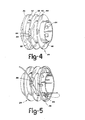
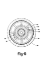
- the spool 24 is more clearly shown in FIGS. 4, 5 and 6.
- the peripheral openings 20 (FIG. 3) are lined up with the respective guide channel 84,86 on the spool 24.
- the line is inserted through a peripheral opening 20 into the respective guide channel 84, which is formed on the intermediate flange 38.
- the guide channel 84 includes a first funnel 88 formed in the intermediate flange 38, and a curved portion 90 formed inside the hub 46 in communication with the first funnel 88 for guiding the flexible line to a position beyond the lower flange 26.
- the lower flange 26 includes a pair of holes 92,94 formed therethrough for receiving the flexible line.
- the user inserts the end of the flexible line into the respective hole 92,94 in the flange 26 to secure the line with respect to the spool 24.
- the user places a finger in the finger depression 95 formed in the lower flange 26 and winds the spool 24 with respect to the housing 14 in order to draw line into the housing and wrap it around the spool. If two flexible lines are used, they will automatically be stored in the separate chambers 40,42 as a result of the sloped surfaces 96 formed on the intermediate flange 38 to guide the flexible line into the appropriate line storage compartment 40,42 upon initial winding of the spool.
- the line is fed first into the housing through the peripheral opening 20 and into the guide channel 84 via the funnel 88.
- the funnel 88 guides the flexible line toward the curved portion 90 of the guide channel, which redirects the line toward the lower flange 26.
- the slot 98 in the hub 46 allows the line to travel from the curved portion 90 to a position beyond the lower flange 26, at which point the end of the flexible line may be inserted into the hole 92 to secure the line with respect to the spool.
- the user places a finger in the finger depression 95 and rotates the spool 24 with respect to the housing 14 in order to draw flexible line into the line storage compartments 40,42 about the hub 46.
- the line is then ready for cutting and the user must bump the bump knob 28 for payout of additional line when desired.
- flexible line 116 may be fed into the line trimmer head 110 without removal of the spool 124.
- line 116 is fed through the eyelet 134 in the peripheral opening 120 of the housing 114.
- the line 116 is then fed up through the large opening 138 in the flange 126.
- the large opening 138 is in communication with both the small opening 136 of the flange and the peripheral opening 120 of the housing.
- the line 116 is inserted through the small opening 136 in the flange 126.
- the other end of the line 116 is then tugged to secure the line within the small and large opening 134,136.
- this embodiment includes only a single spool, and does not include the guide channels disclosed with respect to the first embodiment of the present invention.
- the line trimmer head 210 is connected to the support shaft 212 and includes a housing 214.
- Flexible lines 216,218 extend from a pair of peripheral apertures 220 formed in the housing 214 and are stored within the housing 214.
- the flexible lines 216,218 extend from the line trimmer head 210 for cutting vegetation.
- the line trimmer head 210 rotates about the central axis 221 to rotate the flexible lines for cutting.
- the line trimmer head 210 includes a spool 224, having a flange 226 extending radially outwardly from the periphery thereof.
- a bump knob 228 extends below the spool 224 for engagement with a ground surface to selectively payout additional flexible line 216,218.
- the drive shaft 230 engages the housing 214 to cause rotation of the housing 214.
- the spool 224 is adapted to receive flexible line for storage thereabout.
- the flexible lines extend out of the housing through the pair of eyelets 232,234 in the peripheral openings 220.
- the spool 224 includes a lower flange 226 which is positioned adjacent the open end 236 of the housing 214.
- the spool 224 also includes an upper flange 244 extending from the flange hub 246.
- the upper flange 244 in cooperation with the hub 246 and lower flange 226, forms the line storage compartment 240.
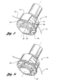
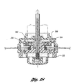
- a spool sub-assembly 248, as shown in Figure 11, is positioned at least partially within the housing 214 adjacent the open end 236 of the housing.
- the spool sub-assembly 248 comprises the spool 224, the cog ring 250 and the ratchet and pawl assembly 252.
- the ratchet and pawl assembly 252 allows rotation of the spool 224 in a first direction with respect to the cog ring 250 for winding line around the spool, while preventing spool rotation in a second direction opposite the first direction for line feed bumping and line trimming operations.
- the spool subassembly 248 is secured together by the bolt 254 and washer 256, and the subassembly 248 is spring-loaded with respect to the housing 214 by the spring 258 for line feed bumping operations, to be described below.
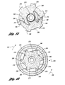
- the ratchet and pawl assembly 252 is more clearly understood with reference to Figures 12, 13 and 16.
- a pair of pawls 260,262 are pivotally secured to the cog ring 250 by the pivot pins 264,266.
- the spring 268 pivotally biases the pawls 260,262 away from the cog ring hub 270.
- the engagement portions 272,274 of the pawls 260,262 are outwardly spring-loaded to facilitate cooperation with the ratchet member 276 formed in the spool flange 244.
- the ratchet member 276 comprises a plurality of ramps 278 and pockets 280 which are engageable with the engagement portions 272,274 of the pawls 260,262.
- the operator For winding line around the spool, the operator simply grips the serrated portion 282 of the spool 224 and rotates the spool in a first direction 284. As the spool is rotated in the first direction 284, line is wound about the spool within the line storage compartment 240.
- the stops 286 on the housing 214 engage the cog ring teeth 288 to prevent rotation of the cog ring 250 with respect to the housing to allow winding of the line.
- the pawls 260,262 ride along the ramps 278 formed by the ratchet member 276 in the spool 224 in order to allow such rotation. In this manner, a "speed-spool" is provided whereby an operator may quickly wind line around the spool 224 while the spool is disposed within the housing 214.
- Rotation of the spool 224 in a second direction 290 with respect to the cog ring 250 is prevented by the pockets 280.
- the pawls 260,262 ride into the pockets 280 in the ratchet member 276, which prevents further rotation of the spool 224 in the second direction 290 with respect to the cog ring 250.
- This relative rotation prevention facilitates line feed bumping and line trimming operations.
- the spool flange 226 includes a set of first holes 290,292 and a set of second holes 294,296 formed through the flange in communication with each other and in communication with the peripheral apertures in the housing to facilitate line feeding.
- the operator simply inserts flexible line 216,218 through the peripheral apertures 220 in the housing 214, as shown in Figure 11, and further inserts the flexible line through the set of first holes 290,292 formed in the spool flange 226, and finally returns the flexible lines 216,218 into the second holes 294,296 formed in the flange 226 adjacent the respective first holes 290,292.
- each line 216,218 tugs each line 216,218 to secure the line with respect to the spool, then grips the serrated portion 282 of the spool 224 and rotates the spool 224 in the first direction 284 with respect to the cog ring 250, as described above, such that the pawls 260,262 cooperate with the ramps 278 to allow such rotation and winding of the flexible line about the spool.
- the self-contained spool subassembly 248 provides the advantage of being a separate subassembly manufacturing operation which provides a spool usable with existing line trimmer head housings.
- the housing 214 includes a base 298, cylindrical sidewall portion 300, a first row of stops 302 positioned inside the housing where the base and sidewall portion meet, and a second row of stops 286 positioned inside the housing 214 along the side wall portion 300 spaced from the base 298 in a manner to allow bump-actuated indexing of the cog teeth 288 between the first and second rows 302,286 of stops for dispensing incremental amounts of line from the spool.
- the operator When payout of additional flexible line from the line storage compartment 240 is desired, the operator simply bumps the bump head 228 on the ground as the line trimmer head is rotating. When the bump head 228 is bumped on the ground, the bump head 228 forces the spool subassembly 248 toward the base 298 of the housing 214. As the subassembly 248 moves toward the housing base 298, the cog teeth 288 disengage from the first row of stops 286, and the spool rotates to payout line until the cog teeth 288 engage the stops 302 to prevent further rotation.
- the spring 258 then forces the spool subassembly 248 away from the housing base 298 to clear the cog teeth 288 away from the stops 302, and the cog ring 250 and spool subassembly 248 continue to rotate further until the cog teeth 288 are in alignment with and engage the stops 286 in the second row.
- the spool subassembly 248 then comes to rest in this position with respect to the housing 214 for line trimming operations.
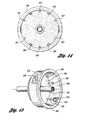
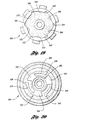
- the spool 320 (shown in Figure 20) comprises a molded-in pawl 322, which includes spring arms 324, 326, 328 supported at the respective base 330, 332, 334.
- the spring arms 324, 326, 328 include knobs 336, 338, 340, respectively, for engagement in the pockets 342, 344, 346, 348, 350, 352 which are integrally molded within the cog ring 356 (shown in Figure 19).
- the spring arms 324, 326, 328 are molded such that they are supported only by the respective base 330, 332, 334 and are free to spring outward from the center of the spool 320 about the respective base 330, 332, 334.
- the respective base 330, 332, 334 of each spring arm 324, 326, 328 is supported by a support ring 360 which is also integrally molded on the spool 320.
- the spool 320 may be rotated in the direction indicated by arrows 362 in Figure 17 for line-winding operations, but is prevented from rotating in the opposite direction by the knobs 336, 338, 340 engaging the pockets 348, 344, 352.
- the arms 324, 326, 328 spring in as they travel up the ramps 364, 366, 368, 370, 372, 374, and return outward as they reach the pockets 342, 344, 346, 348, 350, 352 to prevent opposite rotation.
- the separate pawl and spring assembly illustrated in Figure 16 is eliminated.
- the molded-in spring arms 324, 326, 328 could comprise various configurations, so long as they are configured to have an outward spring bias.
Landscapes
- Life Sciences & Earth Sciences (AREA)
- Environmental Sciences (AREA)
- Harvester Elements (AREA)
- Removal Of Insulation Or Armoring From Wires Or Cables (AREA)
- Sewing Machines And Sewing (AREA)
Claims (16)
- Une tête de taille-herbe à fil, comportant :caractérisée, d'une part, par le fait que la bobine forme un canal de guidage au travers de celle-ci qui communique avec ladite ouverture périphérique pour recevoir une extrémité d'un fil souple introduit par ladite ouverture périphérique et pour guider ladite extrémité de fil souple au travers de la bobine à une position allant au-delà de ladite bride pour faciliter la fixation de ladite extrémité de fil souple par rapport à ladite bobine et, d'autre part, par le fait que la bobine est enroulable à l'intérieur du boítier pour charger le fil souple sur la bobine sans retirer la bobine du boítier.un arbre moteur rotatif ;un boítier, installé sur ledit arbre moteur de manière à tourner avec celui-ci, et ayant une extrémité ouverte et au moins une ouverture périphérique ménagée au travers du boítier ; etune bobine comprenant une bride, ladite bride étant positionnée au moins partiellement à l'intérieur dudit boítier à côté de ladite extrémité ouverte dudit boítier ;
- La tête de taille-herbe à fil de la revendication 1, dans laquelle ladite bobine est fixée axialement par rapport au dit boítier.
- La tête de taille-herbe à fil de la revendication 1 ou de la revendication 2, dans laquelle ladite bobine peut tourner par rapport au dit boítier pour faciliter l'enroulement du fil souple autour de ladite bobine quand celle-ci est positionnée au moins partiellement à l'intérieur dudit boítier.
- La tête de taille-herbe à fil de la revendication 3, comportant en outre plusieurs dents partant soit de ladite bobine soit dudit boítier et un cliquet installé de manière à coulisser par rapport à l'autre de ces deux éléments, c'est-à-dire soit de ladite bobine, soit dudit boítier pour un fonctionnement solidaire sélectif avec les dites dents, ce qui permet la rotation de ladite bobine par rapport au boítier dans un sens et empêche sélectivement la rotation de ladite bobine dans le sens opposé par rapport au dit boítier.
- La tête de taille-herbe à fil de la revendication 4, comportant en outre un déclencheur de cliquet fonctionnant de manière solidaire avec ledit cliquet et saillant au-delà de ladite bobine pour faciliter la poussée dudit déclencheur afin de permettre la rotation de ladite bobine dans le sens inverse par rapport au dit boítier.
- La tête de taille-herbe à fil d'une quelconque des revendications 1 à 5, comportant en outre au moins un renfoncement ménagé dans ladite bride qui permet l'interaction d'un doigt pour effectuer l'enroulement de la bobine.
- Une tête de taille-herbe à fil, comportant :caractérisée, d'une part, par le fait que ladite bride a au moins une paire d'orifices ménagée au travers de celle-ci, les dits orifices communiquant l'un avec l'autre et avec l'ouverture périphérique, ce qui permet de recevoir successivement un fil souple introduisible dans ledit boítier par ladite ouverture périphérique et premièrement par l'une de ladite paire d'orifices et puis par l'autre de ladite paire d'orifices pour fixer ledit fil par rapport au dit boítier et, d'autre part, par le fait que la bobine est enroulable à l'intérieur du boítier pour charger le fil souple sur la bobine sans sortir la bobine du boítier.un arbre moteur rotatif ;un boítier installé sur ledit arbre moteur pour tourner avec celui-ci, ayant au moins une ouverture périphérique ménagée au travers du boítier ; etune bobine ayant au moins une bride saillant radialement vers l'extérieur de sa périphérie, ladite bobine étant positionnée au moins partiellement à l'intérieur dudit boítier ;
- La tête de taille-herbe à fil d'une quelconque des revendications 1 à 7, dans laquelle le dit ensemble de bobine comporte une roue dentée fixée à celui-ci, ladite bobine pouvant tourner dans un premier sens de rotation par rapport à la roue dentée pour enrouler le fil sur la bobine et être immobilisée contre toute rotation dans un deuxième sens opposé au premier sens de rotation pour faciliter la rotation de la bobine et de la roue dentée avec le boítier pour les travaux de taillage.
- La tête de taille-herbe à fil. d'une quelconque des revendications 1 à 8, dans laquelle le dit ensemble de bobine comporte un ensemble à cliquet et rochet formé entre la roue dentée et la bobine pour faciliter la rotation de la bobine dans le premier sens de rotation et empêcher la rotation de la bobine dans le deuxième sens par rapport à la roue dentée.
- La tête de taille-herbe à fil de la revendication 9, dans laquelle l'ensemble à cliquet et rochet comporte :au moins un cliquet connecté à la roue dentée de manière à pivoter et doté d'un ressort par rapport à la roue dentée ; etun élément de rochet réalisé dans ladite bobine à côté de la roue dentée, ledit élément de rochet comportant plusieurs rampes et poches pour fonctionner de manière solidaire avec ledit cliquet afin de permettre ladite rotation de la bobine par rapport à la roue dentée dans un premier sens tout en empêchant la rotation dans ledit deuxième sens.
- La tête de taille-herbe à fil de la revendication 10, dans laquelle la roue dentée comporte des dents et ledit boítier comporte en outre :un fond ;une partie de paroi latérale cylindrique ;une première série de butées positionnées à l'intérieur du boítier où ledit fond et les dites parties de paroi latérales se rencontrent ; etune deuxième rangée de butées positionnées à l'intérieur dudit boítier le long de la dite partie de paroi latérale et espacées dudit fond de manière à permettre l'indexage par éjection des dites dents entre la première et la deuxième rangée de butées pour dévider des quantités incrémentielles de fil de la bobine.
- La tête de taille-herbe à fil d'une quelconque des revendications 1 à 11, dans lequel ladite bride comporte au moins une paire d'orifices ménagés dans celle-ci, lesdits orifices communiquent l'un avec l'autre et avec ladite ouverture périphérique, ce qui permet de recevoir successivement un fil souple introduisible dans ledit boítier par ladite ouverture périphérique et premièrement par l'une de ladite paire d'orifices puis par l'autre de ladite paire d'orifices pour fixer ledit fil par rapport à ladite bobine.
- La tête de taille-herbe à fil d'une quelconque des revendications 1 à 12, dans laquelle le dit ensemble de bobine comporte une roue dentée fixée à celui-ci, ladite bobine pouvant tourner dans un premier sens de rotation par rapport à la roue dentée pour enrouler le fil autour de la bobine et être immobilisée contre toute rotation dans un deuxième sens de rotation opposé au dit premier sens de rotation afin faciliter la rotation de la bobine et de la roue dentée avec le boítier pour les travaux de taillage ; et
dans laquelle ledit ensemble de bobine comporte en outre un cliquet moulé de manière à être intégré avec soit ladite bobine soit ladite roue dentée et un élément de rochet moulé de manière à être intégré à l'autre de ces deux éléments, c'est-à-dire soit ladite bobine soit ladite roue dentée, pour faciliter la rotation de la bobine dans le premier sens et empêcher la rotation de la bobine dans le deuxième sens de rotation par rapport à la roue dentée. - La tête de taille-herbe à fil de la revendication 13, dans laquelle ledit élément de rochet comporte plusieurs rampes et poches pour un fonctionnement solidaire avec ledit cliquet afin de permettre ladite rotation dans le premier sens par rapport à la roue dentée et empêcher la rotation dans le deuxième sens.
- La tête de taille-herbe à fil de la revendication 14, dans laquelle la roue dentée comporte des dents et ledit boítier comporte en outre :un fond ;une partie de paroi latérale cylindrique ;une première rangée de butées positionnées à l'intérieur du boítier où ledit fond et les dites parties de paroi latérales se rencontrent ; etune deuxième rangée de butées positionnées à l'intérieur dudit boítier le long de la dite partie de paroi latérale et espacées dudit fond de manière à permettre l'indexage par éjection des dites dents entre la première et la deuxième rangée de butées pour dévider des quantités incrémentielles de fil de la bobine.
- La tête de taille-herbe à fil d'une quelconque des revendications 1 à 15, dans lequel ladite bride comporte au moins une paire d'orifices ménagée au travers de celle-ci, les dits orifices communiquant l'un avec l'autre et avec ladite ouverture périphérique, ce qui permet de recevoir successivement un fil souple introduisible dans ledit boítier par ladite ouverture périphérique et premièrement par l'une de ladite paire d'orifices puis par l'autre de ladite paire d'orifices pour fixer ledit fil par rapport à ladite bobine.
Priority Applications (1)
| Application Number | Priority Date | Filing Date | Title |
|---|---|---|---|
| EP02077279A EP1240816B1 (fr) | 1996-02-15 | 1997-02-14 | Mécanisme d'amenée du fil pour tondeuse à fil |
Applications Claiming Priority (7)
| Application Number | Priority Date | Filing Date | Title |
|---|---|---|---|
| US601788 | 1996-02-15 | ||
| US08/601,788 US5671536A (en) | 1996-02-15 | 1996-02-15 | Line feed configuration for line trimmers |
| US664157 | 1996-06-14 | ||
| US08/664,157 US5659960A (en) | 1996-02-15 | 1996-06-14 | Line feed configuration for line trimmers |
| US719904 | 1996-09-25 | ||
| US08/719,904 US5806192A (en) | 1996-02-15 | 1996-09-25 | Line feed configuration for line trimmers |
| PCT/US1997/002680 WO1997029627A1 (fr) | 1996-02-15 | 1997-02-14 | Mecanisme d'amenee du fil pour tondeuse a fil |
Related Child Applications (1)
| Application Number | Title | Priority Date | Filing Date |
|---|---|---|---|
| EP02077279A Division EP1240816B1 (fr) | 1996-02-15 | 1997-02-14 | Mécanisme d'amenée du fil pour tondeuse à fil |
Publications (3)
| Publication Number | Publication Date |
|---|---|
| EP0955800A1 EP0955800A1 (fr) | 1999-11-17 |
| EP0955800A4 EP0955800A4 (fr) | 2000-08-30 |
| EP0955800B1 true EP0955800B1 (fr) | 2003-10-29 |
Family
ID=27416837
Family Applications (2)
| Application Number | Title | Priority Date | Filing Date |
|---|---|---|---|
| EP02077279A Expired - Lifetime EP1240816B1 (fr) | 1996-02-15 | 1997-02-14 | Mécanisme d'amenée du fil pour tondeuse à fil |
| EP97907732A Expired - Lifetime EP0955800B1 (fr) | 1996-02-15 | 1997-02-14 | Mecanisme d'amenee du fil pour tondeuse a fil |
Family Applications Before (1)
| Application Number | Title | Priority Date | Filing Date |
|---|---|---|---|
| EP02077279A Expired - Lifetime EP1240816B1 (fr) | 1996-02-15 | 1997-02-14 | Mécanisme d'amenée du fil pour tondeuse à fil |
Country Status (7)
| Country | Link |
|---|---|
| US (1) | US5806192A (fr) |
| EP (2) | EP1240816B1 (fr) |
| JP (1) | JP2000506003A (fr) |
| AU (1) | AU709510B2 (fr) |
| CA (1) | CA2245580C (fr) |
| DE (2) | DE69725886T2 (fr) |
| WO (1) | WO1997029627A1 (fr) |
Cited By (3)
| Publication number | Priority date | Publication date | Assignee | Title |
|---|---|---|---|---|
| US10856466B2 (en) | 2017-08-07 | 2020-12-08 | Nanjing Chervon Industry Co., Ltd. | Grass trimming head and grass trimmer having the same |
| US11818979B2 (en) | 2016-01-22 | 2023-11-21 | Nanjing Chervon Industry Co., Ltd. | Grass trimmer |
| US12622350B2 (en) | 2017-08-07 | 2026-05-12 | Nanjing Chervon Industry Co., Ltd. | Grass trimming head and grass trimmer having the same |
Families Citing this family (37)
| Publication number | Priority date | Publication date | Assignee | Title |
|---|---|---|---|---|
| US6148523A (en) * | 1997-02-14 | 2000-11-21 | Ryobi North America, Inc. | Line feed mechanism for a line trimmer |
| IT1304867B1 (it) * | 1998-07-07 | 2001-04-05 | Arnetoli Motor | Testina tagliaerba con ricarica del filo senza estrazione delrocchetto |
| JP4121210B2 (ja) * | 1999-03-16 | 2008-07-23 | スターテング工業株式会社 | 刈払機用のロータリカッタ |
| US6401344B1 (en) | 1999-09-21 | 2002-06-11 | Mark R. Moore | Head for line trimming apparatus |
| US7111403B2 (en) | 1999-09-21 | 2006-09-26 | Moore Mark R | Head for line trimming apparatus |
| US6684614B2 (en) * | 2000-06-30 | 2004-02-03 | Owen Patrick Greenwell | Mobile power driven vegetation trimmer and line feed control |
| US6952877B2 (en) | 2003-01-10 | 2005-10-11 | Shindaiwa, Inc. | Vegetation cutting device |
| SE0302176D0 (sv) * | 2003-08-07 | 2003-08-07 | Electrolux Ab | Eyelet for a trimmer head |
| US7513046B2 (en) * | 2003-10-02 | 2009-04-07 | Proulx Manufacturing, Inc. | Trimmer head for use in flexible line rotary trimmers having improved line loading mechanism |
| US6901667B2 (en) * | 2003-10-02 | 2005-06-07 | Proulx Manufacturing, Inc. | Trimmer head for use in flexible line rotary trimmers |
| US7581322B2 (en) * | 2003-10-02 | 2009-09-01 | Proulx Manufacturing, Inc. | Trimmer head for use in flexible line rotary trimmers having improved line loading mechanism |
| CN101048059B (zh) * | 2004-09-03 | 2010-10-20 | 普罗克斯制造公司 | 修剪器头部 |
| US7640668B2 (en) * | 2005-12-08 | 2010-01-05 | Kwik Products, Inc. | Quick loading cutting head for a rotary trimmer |
| ITRE20060098A1 (it) * | 2006-08-30 | 2008-02-29 | Tecomec S P A | Testina per decespugliatore con caricamento del filo senza smontaggio |
| US10273112B2 (en) | 2006-11-16 | 2019-04-30 | Torvian Inc. | String trimmer head with curved trimmer line guide |
| US7536792B2 (en) | 2007-01-03 | 2009-05-26 | Moore Mark R | Head for a rotary line trimmer apparatus |
| US8001694B2 (en) * | 2007-10-22 | 2011-08-23 | Mtd Products Inc | Fixed line rotary head trimmer with quick friction rotational lock for string trimmer machine |
| US20090172955A1 (en) * | 2008-01-03 | 2009-07-09 | Morris John F | String trimmer head |
| US9924631B2 (en) | 2008-04-22 | 2018-03-27 | George E. Alliss | Spool for straight through line feed vegetation trimmer apparatus with modules and spokes |
| ITFI20080097A1 (it) | 2008-05-15 | 2009-11-16 | Arnetoli Motor Srl | "una testina tosaerba a filo utilizzabile alternativamente su macchine a rotazione destra o sinistra" |
| WO2010089639A1 (fr) * | 2009-01-22 | 2010-08-12 | Techtronic Industries Company Limited | Tête à fil pour appareil de coupe |
| US9253942B2 (en) * | 2010-09-20 | 2016-02-09 | George E. Alliss | Trimmer head with automatic trimmer line feed mechanism |
| WO2013138752A1 (fr) | 2012-03-15 | 2013-09-19 | Shakespeare Company, Llc | Tête de taille-bordures universellement adaptable et facile à charger dotée d'un bouton à frapper sur le sol et à rotation libre |
| WO2015144197A1 (fr) | 2014-03-24 | 2015-10-01 | Husqvarna Ab | Tête de débroussailleuse à chargement rapide |
| US10130030B2 (en) | 2014-05-27 | 2018-11-20 | Mtd Products Inc | Trimmer head |
| USD970321S1 (en) | 2014-11-20 | 2022-11-22 | Torvent Llc | Line trimmer component |
| US20160183452A1 (en) | 2014-12-29 | 2016-06-30 | Husqvarna Ab | Quick loading trimmer head |
| WO2017147172A1 (fr) * | 2016-02-22 | 2017-08-31 | Mtd Products Inc | Tête de taille-bordures multimode |
| USD825293S1 (en) | 2016-12-12 | 2018-08-14 | First-To-Invent, Llc | Trimmer spool non-radial straight channel |
| US10537057B2 (en) | 2017-04-04 | 2020-01-21 | Black & Decker, Inc. | Spool assembly for a trimmer head |
| US11122735B2 (en) | 2017-09-12 | 2021-09-21 | Milwaukee Electric Tool Corporation | String trimmer head and spool |
| WO2019105789A1 (fr) | 2017-11-30 | 2019-06-06 | Husqvarna Ab | Tête de taille-bordures avec caractéristique de libération de fil améliorée |
| EP3831181B1 (fr) * | 2019-12-04 | 2024-02-21 | Andreas Stihl AG & Co. KG | Bobine de fil pour tête faucheuse à fil |
| JP7650893B2 (ja) * | 2020-04-01 | 2025-03-25 | ハスクバーナ・アーベー | トリマーライン供給の制御 |
| US11903339B1 (en) * | 2022-10-10 | 2024-02-20 | Imack Laydera-Collins | Externally windable trimmer head |
| US11632903B1 (en) | 2022-10-10 | 2023-04-25 | Imack Laydera-Collins | Externally windable trimmer head |
| JP7597436B1 (ja) * | 2024-03-18 | 2024-12-10 | 有限会社とまと不動産 | 刈払機及び刈払機に用いられるコードリールカセット |
Family Cites Families (17)
| Publication number | Priority date | Publication date | Assignee | Title |
|---|---|---|---|---|
| US4035912A (en) * | 1971-12-13 | 1977-07-19 | Weed Eater, Inc. | Rotary cutting assembly |
| US4067108A (en) * | 1971-12-13 | 1978-01-10 | Weed Eater, Inc. | Rotary cutting assembly |
| US4052789A (en) * | 1976-12-02 | 1977-10-11 | Weed Eater, Inc. | Rotary cutting assembly |
| US4134204A (en) * | 1976-06-01 | 1979-01-16 | Perdue Bennie G | Rotary flail cutter system |
| CA1079075A (fr) * | 1976-07-19 | 1980-06-10 | George C. Ballas | Couteau rotatif |
| US4168572A (en) * | 1977-07-11 | 1979-09-25 | Weed Eater, Inc. | Apparatus for cutting vegetation |
| US4151646A (en) * | 1978-02-27 | 1979-05-01 | K & S Industries, Inc. | Flexible line trimmer with line feeding apparatus |
| US4852258A (en) * | 1981-03-19 | 1989-08-01 | White Consolidated Industries, Inc. | Apparatus for cutting vegetation |
| US4276691A (en) * | 1978-07-17 | 1981-07-07 | Palmieri Vincent A | Rotary nylon line vegetation cutter |
| US4271595A (en) * | 1979-07-26 | 1981-06-09 | Hawaiian Motor Company | Housing and cutting line assembly for vegetation cutting apparatus |
| US4483069A (en) * | 1979-08-01 | 1984-11-20 | Emerson Electric Co. | Apparatus for cutting vegetation |
| US4335510A (en) * | 1980-06-18 | 1982-06-22 | Black & Decker, Inc. | String trimmer |
| US4475287A (en) * | 1982-07-01 | 1984-10-09 | The Toro Company | Filament line retaining member |
| JPH0232018Y2 (fr) * | 1986-05-24 | 1990-08-30 | ||
| JP3113270B2 (ja) * | 1990-11-16 | 2000-11-27 | 杉原林機株式会社 | コード型草刈機の刈刃装置におけるコード繰出し機構 |
| GB9315594D0 (en) * | 1993-07-28 | 1993-09-08 | Black & Decker Inc | Improvements in or relating to vegetation cutters |
| JP3167859B2 (ja) * | 1994-04-07 | 2001-05-21 | タナカ工業株式会社 | ナイロンコード型刈払機 |
-
1996
- 1996-09-25 US US08/719,904 patent/US5806192A/en not_active Expired - Fee Related
-
1997
- 1997-02-14 DE DE69725886T patent/DE69725886T2/de not_active Expired - Fee Related
- 1997-02-14 JP JP9529604A patent/JP2000506003A/ja active Pending
- 1997-02-14 CA CA002245580A patent/CA2245580C/fr not_active Expired - Fee Related
- 1997-02-14 AU AU19655/97A patent/AU709510B2/en not_active Ceased
- 1997-02-14 EP EP02077279A patent/EP1240816B1/fr not_active Expired - Lifetime
- 1997-02-14 WO PCT/US1997/002680 patent/WO1997029627A1/fr not_active Ceased
- 1997-02-14 EP EP97907732A patent/EP0955800B1/fr not_active Expired - Lifetime
- 1997-02-14 DE DE69733620T patent/DE69733620T2/de not_active Expired - Fee Related
Cited By (5)
| Publication number | Priority date | Publication date | Assignee | Title |
|---|---|---|---|---|
| US11818979B2 (en) | 2016-01-22 | 2023-11-21 | Nanjing Chervon Industry Co., Ltd. | Grass trimmer |
| US10856466B2 (en) | 2017-08-07 | 2020-12-08 | Nanjing Chervon Industry Co., Ltd. | Grass trimming head and grass trimmer having the same |
| US11503759B2 (en) | 2017-08-07 | 2022-11-22 | Nanjing Chervon Industry Co., Ltd. | Grass trimming head and grass trimmer having the same |
| US11910743B2 (en) | 2017-08-07 | 2024-02-27 | Nanjing Chervon Industry Co., Ltd. | Grass trimming head and grass trimmer having the same |
| US12622350B2 (en) | 2017-08-07 | 2026-05-12 | Nanjing Chervon Industry Co., Ltd. | Grass trimming head and grass trimmer having the same |
Also Published As
| Publication number | Publication date |
|---|---|
| US5806192A (en) | 1998-09-15 |
| EP1240816A1 (fr) | 2002-09-18 |
| CA2245580C (fr) | 2004-08-31 |
| EP1240816B1 (fr) | 2005-06-22 |
| WO1997029627A1 (fr) | 1997-08-21 |
| DE69733620T2 (de) | 2005-12-15 |
| EP0955800A4 (fr) | 2000-08-30 |
| JP2000506003A (ja) | 2000-05-23 |
| DE69733620D1 (de) | 2005-07-28 |
| EP0955800A1 (fr) | 1999-11-17 |
| DE69725886D1 (de) | 2003-12-04 |
| DE69725886T2 (de) | 2004-05-13 |
| CA2245580A1 (fr) | 1997-08-21 |
| AU709510B2 (en) | 1999-09-02 |
| AU1965597A (en) | 1997-09-02 |
Similar Documents
| Publication | Publication Date | Title |
|---|---|---|
| EP1240816B1 (fr) | Mécanisme d'amenée du fil pour tondeuse à fil | |
| US6148523A (en) | Line feed mechanism for a line trimmer | |
| US5659960A (en) | Line feed configuration for line trimmers | |
| US5671536A (en) | Line feed configuration for line trimmers | |
| US20190059213A1 (en) | Trimmer head | |
| US7412768B2 (en) | Invertible trimmer line spool for a vegetation trimmer apparatus | |
| EP1446002B1 (fr) | Tete de fil fixee pour appareils de coupe rotatifs a fil flexible | |
| EP0970596B1 (fr) | Tête de coupe à rechargement de filament sans retrait de la bobine | |
| US5020223A (en) | Simplified bump-feed type cutting head assembly for flexible line trimmers | |
| US6854185B1 (en) | Vegetation trimmer apparatus | |
| EP0351989B2 (fr) | Tête semi-automatique pour faucheuse à filament | |
| EP1795062A2 (fr) | Tête de coupe à chargement rapide pour coupeuse rotative | |
| AU2022201494A1 (en) | Trimmer head | |
| EP0840999B1 (fr) | Tête de coupe munie de moyens d'alimentation en filament | |
| US20260096506A1 (en) | Power tool and compact power feed trimmer head | |
| US20060254060A1 (en) | Vegetation trimmer apparatus |
Legal Events
| Date | Code | Title | Description |
|---|---|---|---|
| PUAI | Public reference made under article 153(3) epc to a published international application that has entered the european phase |
Free format text: ORIGINAL CODE: 0009012 |
|
| 17P | Request for examination filed |
Effective date: 19980909 |
|
| AK | Designated contracting states |
Kind code of ref document: A1 Designated state(s): DE FR GB IT |
|
| RIC1 | Information provided on ipc code assigned before grant |
Free format text: 7A 01D 50/00 A, 7A 01D 34/00 B |
|
| A4 | Supplementary search report drawn up and despatched |
Effective date: 20000713 |
|
| AK | Designated contracting states |
Kind code of ref document: A4 Designated state(s): DE FR GB IT |
|
| 18W | Application withdrawn |
Withdrawal date: 20000918 |
|
| D18W | Application withdrawn (deleted) | ||
| 17Q | First examination report despatched |
Effective date: 20020211 |
|
| RAP1 | Party data changed (applicant data changed or rights of an application transferred) |
Owner name: MTD PRODUCTS, INC. |
|
| GRAH | Despatch of communication of intention to grant a patent |
Free format text: ORIGINAL CODE: EPIDOS IGRA |
|
| GRAS | Grant fee paid |
Free format text: ORIGINAL CODE: EPIDOSNIGR3 |
|
| GRAA | (expected) grant |
Free format text: ORIGINAL CODE: 0009210 |
|
| AK | Designated contracting states |
Kind code of ref document: B1 Designated state(s): DE FR GB IT |
|
| REG | Reference to a national code |
Ref country code: GB Ref legal event code: FG4D |
|
| RIC1 | Information provided on ipc code assigned before grant |
Ipc: 7A 01D 34/00 A |
|
| REF | Corresponds to: |
Ref document number: 69725886 Country of ref document: DE Date of ref document: 20031204 Kind code of ref document: P |
|
| ET | Fr: translation filed | ||
| PLBE | No opposition filed within time limit |
Free format text: ORIGINAL CODE: 0009261 |
|
| STAA | Information on the status of an ep patent application or granted ep patent |
Free format text: STATUS: NO OPPOSITION FILED WITHIN TIME LIMIT |
|
| 26N | No opposition filed |
Effective date: 20040730 |
|
| PGFP | Annual fee paid to national office [announced via postgrant information from national office to epo] |
Ref country code: IT Payment date: 20080228 Year of fee payment: 12 Ref country code: GB Payment date: 20080213 Year of fee payment: 12 Ref country code: DE Payment date: 20080214 Year of fee payment: 12 |
|
| PGFP | Annual fee paid to national office [announced via postgrant information from national office to epo] |
Ref country code: FR Payment date: 20080226 Year of fee payment: 12 |
|
| GBPC | Gb: european patent ceased through non-payment of renewal fee |
Effective date: 20090214 |
|
| REG | Reference to a national code |
Ref country code: FR Ref legal event code: ST Effective date: 20091030 |
|
| PG25 | Lapsed in a contracting state [announced via postgrant information from national office to epo] |
Ref country code: DE Free format text: LAPSE BECAUSE OF NON-PAYMENT OF DUE FEES Effective date: 20090901 |
|
| PG25 | Lapsed in a contracting state [announced via postgrant information from national office to epo] |
Ref country code: GB Free format text: LAPSE BECAUSE OF NON-PAYMENT OF DUE FEES Effective date: 20090214 Ref country code: FR Free format text: LAPSE BECAUSE OF NON-PAYMENT OF DUE FEES Effective date: 20090302 |
|
| PG25 | Lapsed in a contracting state [announced via postgrant information from national office to epo] |
Ref country code: IT Free format text: LAPSE BECAUSE OF NON-PAYMENT OF DUE FEES Effective date: 20090214 |