EP0956251B1 - Dispositif de transport de produits - Google Patents
Dispositif de transport de produits Download PDFInfo
- Publication number
- EP0956251B1 EP0956251B1 EP98900071A EP98900071A EP0956251B1 EP 0956251 B1 EP0956251 B1 EP 0956251B1 EP 98900071 A EP98900071 A EP 98900071A EP 98900071 A EP98900071 A EP 98900071A EP 0956251 B1 EP0956251 B1 EP 0956251B1
- Authority
- EP
- European Patent Office
- Prior art keywords
- horizontal
- oscillations
- elements
- adjustable
- directions
- Prior art date
- Legal status (The legal status is an assumption and is not a legal conclusion. Google has not performed a legal analysis and makes no representation as to the accuracy of the status listed.)
- Expired - Lifetime
Links
- 230000010355 oscillation Effects 0.000 claims description 17
- 230000001360 synchronised effect Effects 0.000 claims description 7
- 229920003023 plastic Polymers 0.000 claims description 2
- 239000004033 plastic Substances 0.000 claims description 2
- 239000011888 foil Substances 0.000 claims 1
- 239000000463 material Substances 0.000 claims 1
- 230000001133 acceleration Effects 0.000 description 4
- 238000004806 packaging method and process Methods 0.000 description 4
- 230000006835 compression Effects 0.000 description 1
- 238000007906 compression Methods 0.000 description 1
- 238000010276 construction Methods 0.000 description 1
- 238000011109 contamination Methods 0.000 description 1
- 230000008878 coupling Effects 0.000 description 1
- 238000010168 coupling process Methods 0.000 description 1
- 238000005859 coupling reaction Methods 0.000 description 1
- 230000005294 ferromagnetic effect Effects 0.000 description 1
- 239000011521 glass Substances 0.000 description 1
- 230000003287 optical effect Effects 0.000 description 1
- 230000000737 periodic effect Effects 0.000 description 1
- 229920002635 polyurethane Polymers 0.000 description 1
- 239000004814 polyurethane Substances 0.000 description 1
- 230000000284 resting effect Effects 0.000 description 1
Images

Classifications
-
- B—PERFORMING OPERATIONS; TRANSPORTING
- B65—CONVEYING; PACKING; STORING; HANDLING THIN OR FILAMENTARY MATERIAL
- B65G—TRANSPORT OR STORAGE DEVICES, e.g. CONVEYORS FOR LOADING OR TIPPING, SHOP CONVEYOR SYSTEMS OR PNEUMATIC TUBE CONVEYORS
- B65G1/00—Storing articles, individually or in orderly arrangement, in warehouses or magazines
- B65G1/02—Storage devices
- B65G1/04—Storage devices mechanical
- B65G1/0478—Storage devices mechanical for matrix-arrangements
-
- B—PERFORMING OPERATIONS; TRANSPORTING
- B65—CONVEYING; PACKING; STORING; HANDLING THIN OR FILAMENTARY MATERIAL
- B65G—TRANSPORT OR STORAGE DEVICES, e.g. CONVEYORS FOR LOADING OR TIPPING, SHOP CONVEYOR SYSTEMS OR PNEUMATIC TUBE CONVEYORS
- B65G27/00—Jigging conveyors
-
- B—PERFORMING OPERATIONS; TRANSPORTING
- B65—CONVEYING; PACKING; STORING; HANDLING THIN OR FILAMENTARY MATERIAL
- B65G—TRANSPORT OR STORAGE DEVICES, e.g. CONVEYORS FOR LOADING OR TIPPING, SHOP CONVEYOR SYSTEMS OR PNEUMATIC TUBE CONVEYORS
- B65G27/00—Jigging conveyors
- B65G27/34—Jigging conveyors comprising a series of co-operating units
-
- B—PERFORMING OPERATIONS; TRANSPORTING
- B65—CONVEYING; PACKING; STORING; HANDLING THIN OR FILAMENTARY MATERIAL
- B65G—TRANSPORT OR STORAGE DEVICES, e.g. CONVEYORS FOR LOADING OR TIPPING, SHOP CONVEYOR SYSTEMS OR PNEUMATIC TUBE CONVEYORS
- B65G47/00—Article or material-handling devices associated with conveyors; Methods employing such devices
- B65G47/22—Devices influencing the relative position or the attitude of articles during transit by conveyors
- B65G47/24—Devices influencing the relative position or the attitude of articles during transit by conveyors orientating the articles
- B65G47/244—Devices influencing the relative position or the attitude of articles during transit by conveyors orientating the articles by turning them about an axis substantially perpendicular to the conveying plane
Definitions
- a transport device is known from US-A-3 174 613, in which between two spaced apart conveyor belts with several rows of rollers with the same conveying direction parallel, horizontal roller axes arranged per row are. The roles are either at the orbital speed conveyor belts or at a speed 1.4 times faster driven. Your upper, common tangent plane corresponds to the top of the conveyor belts.
- the axes of the Rollers of each row can move together by 45 ° from a basic position be pivoted in which they are perpendicular to the conveying direction of the conveyor belts are. Promote in this swung out position the rolls of the products delivered by the first conveyor belt, namely glass panels on a cross conveyor belt.
- From GB-A-2 259 900 is a conveyor device according to the preamble of claims 1 and 2, in which the products are known an almost horizontal table in one of the four selectable Directions can be transported.
- the table consists of a large number of table elements arranged side by side, the translationally synchronous in both directions parallel to the table level swing back and forth. Each table element is additional driven oscillator in the vertical direction, these vertical vibrations synchronized with the horizontal vibrations are.
- the present invention has for its object a device to create the above type with simple construction allows easy adjustment of the transport speed. This task is accomplished through the combination of features of the claims solved.
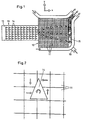
- the device is schematic in plan in the Application shown in a packaging machine.
- the device consists of a horizontal square table 10, the from a multitude of closely spaced square table elements 11 there.
- rows 10 of products 14 are delivered to the table 10.
- the products 14 are in the x direction conveyed and distributed in the y direction and, if necessary, rotated to fill them into packaging container 15 on the right edge of the table.
- the containers 15 are fed via a separate conveyor 16 and then transported for further packaging.
- Each element 11 can have a product resting on it in each transport in any direction.
- the floor plan of the elements 11 does not necessarily have to be be square. It can also be rectangular, triangular or hexagonal his. Other polygonal shapes are possible, too the elements 11 are not uniform in this case.
- FIG 3 is a cross section through part of a first Embodiment shown.
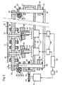
- a frame 20 there are two drive shafts 21 rotatable with vertical axis and axially immovable stored.
- One shaft 21 is via pulleys 22 and a toothed belt 23 via a controller 49 by a speed-controllable Drive motor 24 driven.
- a guide member 25 is attached at the top of the Shafts 21, a guide member 25 is attached.
- a carriage 26 is displaceable transversely to the axis of the shafts 21 guided and lockable by means of screws 27, which Grip through longitudinal slots 28 of link 25.
- the sled 26 each carry an eccentric pin 29 parallel to the shafts 21. By loosening the screws 27 and moving the slide 26 the eccentricity a of the pin 29 can be adjusted.
- the Pins 29 are in a common, horizontal support plate 30 rotatably mounted. At the lower end there is one on each of the shafts 21 Flange 31 attached, which another, not adjustable Eccentric pin 32 carries. The eccentricity of these pins 32 is offset by 90 ° relative to that of the pin 29.
- the pins 32 are rotatably mounted in a coupling rod 33. That’s why two shafts 21 rotatably connected together. While running Motor 24 guides the support plate 30 in a circular motion in its Level off. There is still one eccentric mass on each of the shafts 21 34 attached to balance the balance by the support plate 30.
- Each table element 11 is vertically parallel by means of leaf springs 39 attached to itself slidably on the plate 30.
- Each element 11 has a tappet 40 with a spherical cap in the center End face 41 from.
- the measure of eccentricity the pin 29 laterally offset from the axis of the plunger 40 a servo motor or stepper motor 42 is attached to the frame 20.
- the motor 42 has a vertical output shaft 43.
- On the Shaft 43 is a cylindrical pin 44 with an axis to the Fixed shaft 43 inclined axis.
- On the pin 44 is a cylindrical shoe 45 coaxially attached.
- the shoe 45 has one sloping, flat end face 46 on which the surface 41 of the Tappet 40 rests.
- the angle which the surface 46 has with a Includes radial plane of the shoe 45 corresponds to the angle under which the axes of the shaft 43 and the pin 44 cross. By turning the shoe 45 relative to the pin 44 can therefore be the inclination of the surface 46 with respect to one Set the horizontal level from 0 to the maximum value shown.
- Each motor 42 can be individually controlled by a controller 48, so that the surfaces 46 are individually selectable Are inclined towards.
- the controls 48, 49 are by a common control device 50 controlled.
- the surface of the Table 10 can still by a thin, flexible plate 47 to Example a film made of polyurethane or another plastic be covered, which the spaces 48 between the Bridges table elements 11. This increases the risk of contamination reduced.
- the operation of the device described is as follows:
- the motor 24 rotates at the set, constant speed of for example 10 to 30 Hz, so that the table elements 11 a Carry out a circular motion in your plane, for example with a radius of 5 mm.
- the frequency, the radius a and the stroke h are selected so that the acceleration of the table elements 11 down at least in the area of the top dead center of the lifting vibration is greater than gravitational acceleration, so that Product periodically stands out from the element 11 in question.
- the frequency and eccentricity a is set in this case so that the products 14 at least in phases, namely when the elements accelerate 11 slide down on the surface of the elements 11. At the upward acceleration is the frictional force between the elements 11 and the product 14 larger than during acceleration down so that even in this case a translatory movement of the products 14 on the table 10.
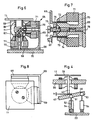
- FIG. 45 A variant of the actuation of the shoe 45 is shown in FIG.
- the shoe 45 is in this case a circular disc, which is mounted on a ball joint 51 in the center.
- the Hinge 51 is mounted on a stand 52 attached to the frame 20.
- At the periphery of the shoe 45 are 90 ° against each other offset two further ball joints 53 arranged, which are adjustable in height by a linear lifting element 54 each.
- the lifting elements 54 are pivotally mounted on the frame 20.
- she can, for example, as stepper motors with threaded spindles or be designed as linear motors with position feedback.
- This variant has the advantage that not only the direction but also the amount of inclination of the surface 46, that is to say the stroke amplitude h is individually adjustable for each table element 11. In order to can 10 different speeds of the on the table Products 14 can be specified in different sectors.
- Deviating from the embodiment shown in Figure 4 can the sliding surface 46 of the shoe 45 also horizontally and the shoe 45 be guided vertically. In this case, he will through a single linear lifting element 54 vertically in sync with the horizontal vibrations with an adjustable amplitude and adjustable phase position with respect to the vibration in the x-direction swinging driven by the lifting element 54.
- Figure 5 shows an application example of this variant for distribution and grouping the products 14 delivered by the belt 12.
- the average conveying speed v x on the table 10 in the transport direction A of the belt 12 is greater than the belt speed.
- the products are delivered in four columns 57, which are shifted laterally in rows in table columns 58 by suitable selection of the conveying direction of the table elements 11 on the table 10.
- the transport direction R of the elements 11 has a component directed against this column 58 each on the right and left of one of these columns 58.
- the products 14 are grouped on the right edge of the table 10 into two groups of six fields 59 each (formed by an element 11).
- the transport direction of the elements 11 immediately surrounding these fields 59 is directed radially to these fields.
- the transport speed of the fields 59 is 0. As soon as a group 60 is complete, it is transported away for packaging, for example by means of a suction gripper.
- the rows 13 are moved in the x direction with traveling waves.
- the elements 11 transport at the target speed in the x direction.
- the elements 11 lying immediately to the right transport slower, those to the left of them faster. This makes it possible to keep the rows 13 aligned on the table 10 and to align them if they are delivered from the belt 12 unaligned.
- the device is preferably controlled by an optical recognition device (not shown) arranged above the table 10.
- FIGS. 6 to 8 show a further embodiment of the invention shown.
- a separate drive 65 is mounted on the frame 20.
- On the plate-shaped table element 11 is below a square tube 66 with a center flat floor 67 mounted.
- the tube 66 is surrounded by a cube-shaped one Carrier 68 with three mutually perpendicular Walls 69.
- the carrier 68 is mounted on the frame 20.
- At every Wall 69 is a ferromagnetic armature 70 with a coil 71 attached.
- Plunger coil 72 dips into a cylindrical air gap 73 of the armature 70 a.
- a screw 74 is screwed coaxially into the armature 70.
- An alternating current is applied to the three moving coils 72 a selectable, same frequency.
- the phase position and the The amplitude of the AC voltage is individual between the three Coils 73 adjustable.
- 72 for the two coils with the horizontal axis 78 the amplitude is the same and the phase is around Moved 90 °, the table element again leads a circular Movement parallel to yourself.
- the table element instead of circular also an elliptical or a linear, horizontal Vibration of the table element 11 can be achieved, depending on the phase position and amplitude ratio of the to the coils 72 with horizontal Axis applied voltage.
- the three moving coil arrangements 70 to 75 can also be replaced are driven by three linear motors with position feedback. This has the The advantage that the vibration amplitudes are independent of the weight or the presence of the products 14. This is special advantageous when moving a product 14 between two Table elements 11.
Landscapes
- Engineering & Computer Science (AREA)
- Mechanical Engineering (AREA)
- Physics & Mathematics (AREA)
- Mathematical Physics (AREA)
- Jigging Conveyors (AREA)
- Attitude Control For Articles On Conveyors (AREA)
Claims (11)
- Dispositif de transport de produits, dans une direction (x, y) pouvant être sélectionnée, avec une table (10) à peu près horizontale, présentant une pluralité d'éléments de table (11) disposés les uns à côté des autres, chaque élément de table (11) étant entraíné en translation dans les deux directions (x, y) par un dispositif d'entraínement (21 à 24; 65), provoquant un mouvement oscillatoire dans un sens et dans l'autre, parallèlement au plan de la table, et les oscillations effectuées dans les deux directions (x, y) étant synchronisées ensembles, et dans lequel chaque élément de table (11) est en outre entraíné selon un mouvement oscillatoire en direction verticale (z), et dans lequel ce mouvement oscillatoire vertical est synchronisé par rapport aux mouvements oscillatoires horizontaux, caractérisé en ce que le mouvement oscillatoire vertical est réglable en phase par rapport aux mouvements oscillatoires horizontaux de chaque élément de table (11), et en ce que l'amplitude de course (h) du mouvement oscillatoire vertical de chaque élément de table (11) est réglable individuellement.
- Dispositif de transport de produits, dans une direction (x, y) pouvant être sélectionnée, avec une table (10) à peu près horizontale, présentant une pluralité d'éléments de table (11) disposés les uns à côté des autres, dans lequel chaque élément de table (11) est entraíné en translation dans les deux directions (x, y) par un dispositif d'entraínement (21 à 24; 65), provoquant un mouvement oscillatoire dans un sens et dans l'autre, parallèlement au plan de la table, et dans lequel les oscillations effectuées dans les deux directions (x, y) sont synchronisées ensemble, et chaque élément de table (11) est en outre entraíné selon un mouvement oscillatoire en direction verticale (z), et ce mouvement oscillatoire vertical est synchronisé envers les mouvements oscillatoires horizontaux, caractérisé en ce que le mouvement oscillatoire vertical est réglable en phase par rapport aux mouvements oscillatoires horizontaux de chaque élément de table (11), et en ce que tous les éléments de table (11) sont montés de façon déplaçable verticalement sur un support (30), et le support (30) est entraíné en un mouvement oscillatoire dans les deux directions horizontales (x, y) par un entraínement commun (21 à 24).
- Dispositif selon la revendication 2 ou 3, dans lequel l'entraínement (21 à 24) comprend au moins deux arbres d'entraínement (21) verticaux, sur lesquels le support (30) est monté de façon excentrique.
- Dispositif selon l'une des revendications 2 ou 3, dans lequel un poussoir (40) fait saillie perpendiculairement vers le bas, de chaque élément de table (11), poussoir dont l'extrémité frontale (41) repose sur une surface (46), inclinée par rapport au plan de la table (10), d'un élément support (45), et la direction de la ligne de pente de la surface (46) est réglable.
- Dispositif selon l'une des revendications 2 à 5, caractérisé, en ce que l'amplitude de course (h) du mouvement oscillatoire vertical est réglable individuellement pour chaque élément de table (11).
- Dispositif selon la revendication 1, caractérisé en ce que chaque élément de table (11) présente un dispositif d'entraínement (65) propre.
- Dispositif selon l'une des revendications 1 à 6, caractérisé en ce que la course d'oscillation (a) dans les deux directions horizontales (x, y) est identique et, de préférence, réglable.
- Dispositif selon l'une des revendications 1 à 7, caractérisé en ce que les mouvements oscillatoires effectués dans les deux directions horizontales (x, y) sont mutuellement déphasées de 90°, de sorte que les éléments de table (11) effectuent un mouvement dont la trajectoire est circulaire.
- Dispositif selon l'une des revendications 1 à 8, caractérisé en ce que la fréquence des oscillations est réglable.
- Dispositif selon l'une des revendications 1 à 9, caractérisé en ce que les éléments de table (11) ont un profil triangulaire, rectangulaire ou hexagonal.
- Dispositif selon l'une des revendications 1 à 10, caractérisé en ce que l'ensemble des éléments de table (11) sont couverts par une feuille de couverture (47) flexible, commune, en particulier une feuille de matière synthétique, qui couvre les espaces intermédiaires (48) existant entre les éléments de table (11).
Applications Claiming Priority (3)
| Application Number | Priority Date | Filing Date | Title |
|---|---|---|---|
| CH17997 | 1997-01-28 | ||
| CH17997 | 1997-01-28 | ||
| PCT/CH1998/000013 WO1998032679A1 (fr) | 1997-01-28 | 1998-01-15 | Dispositif de transport de produits |
Publications (2)
| Publication Number | Publication Date |
|---|---|
| EP0956251A1 EP0956251A1 (fr) | 1999-11-17 |
| EP0956251B1 true EP0956251B1 (fr) | 2001-10-04 |
Family
ID=4181074
Family Applications (1)
| Application Number | Title | Priority Date | Filing Date |
|---|---|---|---|
| EP98900071A Expired - Lifetime EP0956251B1 (fr) | 1997-01-28 | 1998-01-15 | Dispositif de transport de produits |
Country Status (5)
| Country | Link |
|---|---|
| US (1) | US6189677B1 (fr) |
| EP (1) | EP0956251B1 (fr) |
| AU (1) | AU5305798A (fr) |
| DE (1) | DE59801630D1 (fr) |
| WO (1) | WO1998032679A1 (fr) |
Cited By (1)
| Publication number | Priority date | Publication date | Assignee | Title |
|---|---|---|---|---|
| DE102023103664A1 (de) * | 2023-02-15 | 2024-08-22 | Otto-von-Guericke-Universität Magdeburg, Körperschaft des öffentlichen Rechts | Fördervorrichtung zum flächigen Fortbewegen und Vereinzeln einer Gutmenge |
Families Citing this family (20)
| Publication number | Priority date | Publication date | Assignee | Title |
|---|---|---|---|---|
| DE19927251C2 (de) * | 1999-06-15 | 2001-05-17 | Siemens Ag | Vorrichtung zum Handhaben von Stückgütern |
| JP2002120812A (ja) * | 2000-10-16 | 2002-04-23 | Ishida Co Ltd | 箱詰めシステムにおける製品振り分け機構 |
| US7036653B2 (en) | 2002-01-29 | 2006-05-02 | Siemens Technology-To-Business Center Llc | Load manipulation system |
| US6910569B2 (en) * | 2002-01-29 | 2005-06-28 | Siemens Technology-To-Business Center, Llc | Load singulation system and method |
| CA2503863A1 (fr) * | 2002-10-29 | 2004-05-13 | Siemens Aktiengesellschaft | Systeme de bande transporteuse permettant de manipuler des articles distribues |
| US20050107909A1 (en) * | 2003-11-14 | 2005-05-19 | Siemens Technology-To-Business Center Llc | Systems and methods for programming motion control |
| US20050107911A1 (en) * | 2003-11-14 | 2005-05-19 | Siemens Technology-To-Business Center Llc | Systems and methods for controlling load motion actuators |
| US20050065633A1 (en) * | 2003-11-14 | 2005-03-24 | Michael Wynblatt | Systems and methods for relative control of load motion actuators |
| DE102004022060A1 (de) * | 2004-05-05 | 2005-12-01 | Siemens Ag | Fördereinrichtung zum Transportieren von Fördergut und Verfahren zum Betreiben der Fördereinrichtung |
| US7389867B2 (en) * | 2005-05-27 | 2008-06-24 | Scandia Technologies | Systems and methods for orienting and conveying articles |
| WO2007109109A2 (fr) * | 2006-03-16 | 2007-09-27 | Northwestern University | Procédé et appareil de manipulation de pièces |
| JP5647777B2 (ja) * | 2009-08-11 | 2015-01-07 | レオン自動機株式会社 | 食品生地切断片旋回装置 |
| JP5466989B2 (ja) * | 2010-04-28 | 2014-04-09 | レオン自動機株式会社 | 食品生地の整列方法及び装置 |
| DE102014106756B4 (de) | 2014-05-14 | 2025-12-04 | Stadler Anlagenbau Gmbh | Müllgemischausbreitungsvorrichtung |
| DE102015117241B4 (de) | 2015-10-09 | 2018-11-15 | Deutsche Post Ag | Ansteuerung einer Förderanlage |
| US10549923B2 (en) | 2016-02-26 | 2020-02-04 | Douglas Machine Inc. | Article accumulation pattern building load plate |
| ES2750852T3 (es) * | 2016-10-31 | 2020-03-27 | Rheon Automatic Machinery Co | Un aparato para alinear y posicionar trozos de masa alimenticia |
| TWI669259B (zh) * | 2019-02-19 | 2019-08-21 | 住華科技股份有限公司 | 輸送裝置 |
| TWI895527B (zh) * | 2021-10-19 | 2025-09-01 | 日商大福股份有限公司 | 物品搬送裝置 |
| DE102023114198A1 (de) * | 2023-05-31 | 2024-12-05 | TRUMPF Werkzeugmaschinen SE + Co. KG | Vibrationsförderer zum gerichteten Fördern eines Werkstücks |
Family Cites Families (6)
| Publication number | Priority date | Publication date | Assignee | Title |
|---|---|---|---|---|
| US3174613A (en) * | 1963-02-25 | 1965-03-23 | Saint Gobain Corp | Transfer conveyor |
| US3613860A (en) * | 1970-07-09 | 1971-10-19 | Fred L Waite | Unscrambling conveyor for baked goods |
| IT1157862B (it) * | 1982-02-12 | 1987-02-18 | C I M Srl | Dispositivo di convogliamento e posizionamento senza ribaltamento di triangoli di pasta alimentare in macchine avvolgitrici di cornetti |
| US5145049A (en) * | 1990-10-12 | 1992-09-08 | Mcclurkin Jack | Pattern forming conveyor |
| GB9120301D0 (en) * | 1991-09-24 | 1991-11-06 | Post Office | Distribution apparatus |
| IL101435A (en) * | 1992-03-31 | 1998-02-08 | Assa Ind C S Ltd | Storing system and method |
-
1998
- 1998-01-15 DE DE59801630T patent/DE59801630D1/de not_active Expired - Fee Related
- 1998-01-15 WO PCT/CH1998/000013 patent/WO1998032679A1/fr not_active Ceased
- 1998-01-15 AU AU53057/98A patent/AU5305798A/en not_active Abandoned
- 1998-01-15 EP EP98900071A patent/EP0956251B1/fr not_active Expired - Lifetime
-
1999
- 1999-07-27 US US09/361,141 patent/US6189677B1/en not_active Expired - Fee Related
Cited By (1)
| Publication number | Priority date | Publication date | Assignee | Title |
|---|---|---|---|---|
| DE102023103664A1 (de) * | 2023-02-15 | 2024-08-22 | Otto-von-Guericke-Universität Magdeburg, Körperschaft des öffentlichen Rechts | Fördervorrichtung zum flächigen Fortbewegen und Vereinzeln einer Gutmenge |
Also Published As
| Publication number | Publication date |
|---|---|
| US6189677B1 (en) | 2001-02-20 |
| DE59801630D1 (de) | 2001-11-08 |
| AU5305798A (en) | 1998-08-18 |
| WO1998032679A1 (fr) | 1998-07-30 |
| EP0956251A1 (fr) | 1999-11-17 |
Similar Documents
| Publication | Publication Date | Title |
|---|---|---|
| EP0956251B1 (fr) | Dispositif de transport de produits | |
| AU609869B2 (en) | Lane adjusting apparatus for bottle guides | |
| EP0415154B1 (fr) | Méthode pour inspecter des objets à partir de différents angles visuels | |
| DE69121230T2 (de) | Einrichtung zum Verteilen und Sammeln von zu fördernden Produkten | |
| DE60311778T2 (de) | Zurückziehbare übergabeeinrichtung für eine dosiervorrichtung | |
| EP0960814A1 (fr) | Dispositif pour alimenter des objets à une machine d'emballage | |
| EP0491658A1 (fr) | Procédé et dispositif pour déformer sous forme d'ondulation un matériau en feuilles | |
| DD295326A5 (de) | Verfahren und vorrichtung zum sukzessiven zufuehren flacher produkte | |
| EP3357839A1 (fr) | Procédé et système de transport destinés à manipuler un flux de produits initial | |
| DE60301621T2 (de) | Fliessband zum transport von tabakmaterial | |
| DE3034339T1 (de) | Workpiece conveying apparatus | |
| DE60113343T2 (de) | Zuordnungsmechanismus für eine Waage | |
| DE60206199T2 (de) | Handhabungssystem für eine last | |
| KR20170137288A (ko) | 토출 방향 조절 가능한 로봇 디스펜서 | |
| DE2356355A1 (de) | Massenausgeglichener schuettelfoerderer | |
| CH663404A5 (en) | Method for the conveying of mass parts and apparatus for carrying out the method | |
| DE2205355B2 (de) | Schwingförderer mit einer wahlweise in unterschiedlichen Schwingrichtungen antreibbaren Förderrinne | |
| US4986056A (en) | Lane adjusting apparatus for bottle guides | |
| EP3670400A1 (fr) | Installation de mise en uvre et procédé de mise en uvre | |
| EP0868349A1 (fr) | Dispositif pour la formation de groupes de produits en forme de disques empiles | |
| WO2004054367A1 (fr) | Dispositif d'acheminement pour matieres a cuire | |
| DE69008523T2 (de) | Steuervorrichtung für produkte. | |
| DE102008000892A1 (de) | Zuführsystem für Kleinteile | |
| DE4210507C2 (de) | Vorrichtung zur Einstellung von wenigstens zwei auf Unwuchtwellen umlaufenden Unwuchten in ihrer Unwuchtlage zueinander | |
| DE69618871T2 (de) | Artikelauswahl- und Verteilungsvorrichtung |
Legal Events
| Date | Code | Title | Description |
|---|---|---|---|
| PUAI | Public reference made under article 153(3) epc to a published international application that has entered the european phase |
Free format text: ORIGINAL CODE: 0009012 |
|
| 17P | Request for examination filed |
Effective date: 19990708 |
|
| AK | Designated contracting states |
Kind code of ref document: A1 Designated state(s): CH DE FR GB IT LI NL |
|
| GRAG | Despatch of communication of intention to grant |
Free format text: ORIGINAL CODE: EPIDOS AGRA |
|
| 17Q | First examination report despatched |
Effective date: 20010531 |
|
| GRAG | Despatch of communication of intention to grant |
Free format text: ORIGINAL CODE: EPIDOS AGRA |
|
| GRAH | Despatch of communication of intention to grant a patent |
Free format text: ORIGINAL CODE: EPIDOS IGRA |
|
| GRAH | Despatch of communication of intention to grant a patent |
Free format text: ORIGINAL CODE: EPIDOS IGRA |
|
| GRAA | (expected) grant |
Free format text: ORIGINAL CODE: 0009210 |
|
| AK | Designated contracting states |
Kind code of ref document: B1 Designated state(s): CH DE FR GB IT LI NL |
|
| REG | Reference to a national code |
Ref country code: CH Ref legal event code: NV Representative=s name: ISLER & PEDRAZZINI AG Ref country code: CH Ref legal event code: EP |
|
| REF | Corresponds to: |
Ref document number: 59801630 Country of ref document: DE Date of ref document: 20011108 |
|
| REG | Reference to a national code |
Ref country code: GB Ref legal event code: IF02 |
|
| GBT | Gb: translation of ep patent filed (gb section 77(6)(a)/1977) |
Effective date: 20011217 |
|
| ET | Fr: translation filed | ||
| PLBE | No opposition filed within time limit |
Free format text: ORIGINAL CODE: 0009261 |
|
| STAA | Information on the status of an ep patent application or granted ep patent |
Free format text: STATUS: NO OPPOSITION FILED WITHIN TIME LIMIT |
|
| 26N | No opposition filed | ||
| PGFP | Annual fee paid to national office [announced via postgrant information from national office to epo] |
Ref country code: CH Payment date: 20021118 Year of fee payment: 6 |
|
| PGFP | Annual fee paid to national office [announced via postgrant information from national office to epo] |
Ref country code: FR Payment date: 20021209 Year of fee payment: 6 |
|
| PGFP | Annual fee paid to national office [announced via postgrant information from national office to epo] |
Ref country code: NL Payment date: 20021212 Year of fee payment: 6 Ref country code: GB Payment date: 20021212 Year of fee payment: 6 |
|
| PGFP | Annual fee paid to national office [announced via postgrant information from national office to epo] |
Ref country code: DE Payment date: 20021213 Year of fee payment: 6 |
|
| PG25 | Lapsed in a contracting state [announced via postgrant information from national office to epo] |
Ref country code: GB Free format text: LAPSE BECAUSE OF NON-PAYMENT OF DUE FEES Effective date: 20040115 |
|
| PG25 | Lapsed in a contracting state [announced via postgrant information from national office to epo] |
Ref country code: LI Free format text: LAPSE BECAUSE OF NON-PAYMENT OF DUE FEES Effective date: 20040131 Ref country code: CH Free format text: LAPSE BECAUSE OF NON-PAYMENT OF DUE FEES Effective date: 20040131 |
|
| PG25 | Lapsed in a contracting state [announced via postgrant information from national office to epo] |
Ref country code: NL Free format text: LAPSE BECAUSE OF NON-PAYMENT OF DUE FEES Effective date: 20040801 |
|
| PG25 | Lapsed in a contracting state [announced via postgrant information from national office to epo] |
Ref country code: DE Free format text: LAPSE BECAUSE OF NON-PAYMENT OF DUE FEES Effective date: 20040803 |
|
| GBPC | Gb: european patent ceased through non-payment of renewal fee |
Effective date: 20040115 |
|
| REG | Reference to a national code |
Ref country code: CH Ref legal event code: PL |
|
| PG25 | Lapsed in a contracting state [announced via postgrant information from national office to epo] |
Ref country code: FR Free format text: LAPSE BECAUSE OF NON-PAYMENT OF DUE FEES Effective date: 20040930 |
|
| NLV4 | Nl: lapsed or anulled due to non-payment of the annual fee |
Effective date: 20040801 |
|
| REG | Reference to a national code |
Ref country code: FR Ref legal event code: ST |
|
| PG25 | Lapsed in a contracting state [announced via postgrant information from national office to epo] |
Ref country code: IT Free format text: LAPSE BECAUSE OF NON-PAYMENT OF DUE FEES Effective date: 20050115 |