EP0956426B1 - Appareil et procede d'assemblage d'un bloc rotatif obturateur de puits - Google Patents
Appareil et procede d'assemblage d'un bloc rotatif obturateur de puits Download PDFInfo
- Publication number
- EP0956426B1 EP0956426B1 EP97951718A EP97951718A EP0956426B1 EP 0956426 B1 EP0956426 B1 EP 0956426B1 EP 97951718 A EP97951718 A EP 97951718A EP 97951718 A EP97951718 A EP 97951718A EP 0956426 B1 EP0956426 B1 EP 0956426B1
- Authority
- EP
- European Patent Office
- Prior art keywords
- blowout preventer
- rotating
- spindle assembly
- assembly
- lugs
- Prior art date
- Legal status (The legal status is an assumption and is not a legal conclusion. Google has not performed a legal analysis and makes no representation as to the accuracy of the status listed.)
- Expired - Lifetime
Links
- 238000000034 method Methods 0.000 title claims description 4
- 230000020347 spindle assembly Effects 0.000 claims description 30
- 239000012530 fluid Substances 0.000 claims description 5
- 238000005553 drilling Methods 0.000 description 11
- VNWKTOKETHGBQD-UHFFFAOYSA-N methane Chemical compound C VNWKTOKETHGBQD-UHFFFAOYSA-N 0.000 description 2
- 230000000295 complement effect Effects 0.000 description 1
- 238000005260 corrosion Methods 0.000 description 1
- 230000007797 corrosion Effects 0.000 description 1
- 230000008878 coupling Effects 0.000 description 1
- 238000010168 coupling process Methods 0.000 description 1
- 238000005859 coupling reaction Methods 0.000 description 1
- 239000003345 natural gas Substances 0.000 description 1
Images

Classifications
-
- E—FIXED CONSTRUCTIONS
- E21—EARTH OR ROCK DRILLING; MINING
- E21B—EARTH OR ROCK DRILLING; OBTAINING OIL, GAS, WATER, SOLUBLE OR MELTABLE MATERIALS OR A SLURRY OF MINERALS FROM WELLS
- E21B33/00—Sealing or packing boreholes or wells
- E21B33/02—Surface sealing or packing
- E21B33/08—Wipers; Oil savers
- E21B33/085—Rotatable packing means, e.g. rotating blow-out preventers
Definitions
- This invention relates to rotating blowout preventers, sometimes called rotating drilling heads or rotating kelly packers generally, and in particular to apparatus for and a method of connecting and disconnecting the rotating assembly of a rotating blowout preventer to and from the non-rotating body that is attached to the blowout preventer stack.
- Rotating blowout preventers seal tightly around kellys, drill pipe, drill collars, tubing or casing and are used for drilling in areas susceptible to kicks or blowouts, for drilling under pressure, for drilling with reverse circulation and when circulating with natural gas or air. They can be used for drilling with pressure in the well. They will also allow pipe to be stripped in and out of the hole with pressure in the well. These situations where operations are being conducted under pressure are referred to as "under balance" drilling as opposed to balanced drilling where the mud system is balanced and there is no need for seals between the drill pipe, kelly, etc., to prevent fluid from the well bore from flowing upwardly past the mud return line.
- Rotating blowout preventers generally include a stationary body that is mounted on top of the blowout preventer stack and a removable rotating spindle assembly that is latched into the body and has a rotating portion that rotates with the kelly during drilling operation.
- the rotating spindle assembly includes a stripper rubber that provides a seal between the rotating spindle assembly and the kelly or drill pipe. Whenever it is necessary to remove the entire rotating spindle assembly, it can be released from the housing and moved upwardly with the kelly to allow a joint of pipe to be added to the drill string or replacement of the rotating spindle assembly by either another rotating spindle assembly or a flanged riser.
- the rotating assembly is bolted or clamped to the housing, which makes releasing and reconnecting the rotating spindle assembly to the housing time-consuming and complicated.
- US-A-4,754,820 discloses a rotating blowout preventer in which an upper body assembly, which includes a rotary tube and rubber stripper, is releasably secured to a fixed tubular body by means of an external rotary clamp.
- the upper body assembly and the rotary clamp have complementary radial segments and grooves whereby radial segments on the upper body assembly may be passed through and beneath the clamp which is then rotated to clamp the segments to the fixed tubular body.
- D1 describes this arrangement as being “a bayonet-type coupler arrangement", but it is not a "bayonet” coupling in the normal sense of the term.
- the arrangement disclosed in D1 is relatively complex. It relies on the use of a hydraulic motor and pinion gear to rotate the clamp.
- the clamp, the interengaging segments, and the hydraulic motor and pinion gear are on the exterior of the apparatus where they are likely to be degraded by corrosion or the presence of extraneous matter.
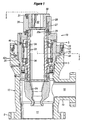
- the drilling head of FIG. 1 includes tubular body 10 having a longitudinally extending central opening 11 and lower flange 12 for bolting the body to the top of a blowout preventer stack.
- Mud return line 14 extends laterally from body 10 to provide passageway 16 through which drilling mud, or whatever fluid is flowing from the well, to flow laterally from opening 11 to the mud pits.
- Mounted in opening 11 in body 10 is rotating spindle assembly 18.
- the assembly includes non-rotating spindle assembly housing 20 and rotating sleeve 22 that extends through the rotating spindle assembly housing and is connected at its lower end to stripper rubber 24.
- Sleeve 22 is connected at its upper end to upper drive bushing assembly 26.
- This assembly includes collar 28 that is attached to sleeve 22 by bolt 27 and drive ring 29 that is attached to sleeve 22 by threads 29a.
- Kelly bushing 30 is-attached to collar 28 by cap screws 31.
- the kelly bushing is provided with a hex or a square opening 32 through which the kelly extends. Whether it is a hex or a square opening will depend upon the kelly, of course, but this provides a drive connection between the kelly and the rotating spindle assembly so that the rotating spindle assembly will rotate with the kelly.
- Upper and lower bearings 34 and 36 support the spindle assembly for rotation relative to stationary body 20 of the spindle assembly.
- rotating spindle assembly 18 is held in body 10 of the rotating blowout preventer by lugs 40, four of which are shown in this embodiment. These lugs are integrally attached to the outside of housing 20.
- the rotating spindle assembly is locked in the housing by lowering the assembly into opening 11 of body 10 with lugs 40 passing through vertical slots 42 in annular housing ring 37 mounted on the top of body 10 by bolts 39, as shown in FIGS. 2 and 3.
- lugs reach bottom 42a of the vertical slots, they are then moved laterally into horizontal grooves 44 in housing ring 37.
- the lugs are held in the horizontal grooves 42 by lock pin 46.
Landscapes
- Life Sciences & Earth Sciences (AREA)
- Engineering & Computer Science (AREA)
- Geology (AREA)
- Mining & Mineral Resources (AREA)
- Physics & Mathematics (AREA)
- Environmental & Geological Engineering (AREA)
- Fluid Mechanics (AREA)
- General Life Sciences & Earth Sciences (AREA)
- Geochemistry & Mineralogy (AREA)
- Earth Drilling (AREA)
- Filling Or Discharging Of Gas Storage Vessels (AREA)
Claims (4)
- Un bloc obturateur de puits rotatif comprenant :caractérisé en ce qu'une portion supérieure de la surface intérieure dudit orifice axial (11) dans le corps de bloc obturateur de puits (10) est pourvue de fentes sensiblement configurées en L (42, 44),un corps de bloc obturateur de puits (10) destiné à être monté sur un empilement de bloc obturateur de puits, ledit corps de bloc obturateur de puits (10) étant percé d'un orifice axial central (11) dans lequel est reçu du fluide provenant d'un alésage de puits et présentant une conduite d'écoulement latérale (14) dans laquelle le fluide provenant de l'alésage de puits peut s'écouler latéralement et sortir du corps de bloc obturateur de puits (10), etun assemblage à broche rotatif () pouvant s'engager de façon sélective dans le corps de bloc obturateur de puits (10), l'assemblage à broche rotatif (20 à 24) comprenant un boítier de broche (20) destiné à être monté dans le corps de bloc obturateur de puits (10), un tube formant broche (22) et un caoutchouc formant garniture d'étanchéité (24) pour tourner avec l'assemblage à broche (20 à 24) et fournir un joint entre celui-ci et la portion de train de tiges qui s'étend à travers l'assemblage à broche () afin de détourner le fluide jusqu'à la conduite d'écoulement latérale (14) ;
et en ce que le boítier de broche (20) est pourvu d'oreilles (40) agencées pour s'engager dans les fentes sensiblement configurées en L (42, 44). - Le bloc obturateur de puits rotatif de la revendication 1, dans lequel chacune des fentes sensiblement configurées en L (42, 44) comprend une fente axiale (42) et une fente circonférentielle communicante (44), l'assemblage comprenant de plus une barre de verrouillage (46) pouvant s'engager de façon sélective dans une fente axiale (42) afin de verrouiller les oreilles (40) dans les fentes circonférentielles (44).
- Le bloc obturateur de puits rotatif de la revendication 1 ou de la revendication 2 comprenant de plus une fourrure d'entraínement (30) attachée à l'assemblage à broche rotatif (20 à 24).
- Une méthode pour engager de façon sélective un assemblage à broche rotatif (20 à 24) d'un bloc obturateur de puits rotatif dans un corps de bloc obturateur de puits (10), consistant :à engager des oreilles (40) dont est pourvu un boítier de broche (20) dans des fentes sensiblement configurées en L (42, 44) dont est pourvue une surface intérieure supérieure du corps de bloc obturateur de puits (10), età déplacer les oreilles (40) en un mouvement sensiblement configuré en L dans les fentes sensiblement configurées en L (42, 44) afin de raccorder l'assemblage à broche rotatif (20 à 24) au corps de bloc obturateur de puits (10).
Applications Claiming Priority (3)
| Application Number | Priority Date | Filing Date | Title |
|---|---|---|---|
| US08/770,719 US5848643A (en) | 1996-12-19 | 1996-12-19 | Rotating blowout preventer |
| US770719 | 1996-12-19 | ||
| PCT/US1997/023188 WO1998027313A1 (fr) | 1996-12-19 | 1997-12-16 | Appareil et procede d'assemblage d'un bloc rotatif obturateur de puits |
Publications (2)
| Publication Number | Publication Date |
|---|---|
| EP0956426A1 EP0956426A1 (fr) | 1999-11-17 |
| EP0956426B1 true EP0956426B1 (fr) | 2002-10-23 |
Family
ID=25089467
Family Applications (1)
| Application Number | Title | Priority Date | Filing Date |
|---|---|---|---|
| EP97951718A Expired - Lifetime EP0956426B1 (fr) | 1996-12-19 | 1997-12-16 | Appareil et procede d'assemblage d'un bloc rotatif obturateur de puits |
Country Status (6)
| Country | Link |
|---|---|
| US (1) | US5848643A (fr) |
| EP (1) | EP0956426B1 (fr) |
| AU (1) | AU5528598A (fr) |
| CA (1) | CA2275445C (fr) |
| DE (1) | DE69716646D1 (fr) |
| WO (1) | WO1998027313A1 (fr) |
Cited By (1)
| Publication number | Priority date | Publication date | Assignee | Title |
|---|---|---|---|---|
| EP4248056A4 (fr) * | 2020-11-19 | 2024-10-23 | Opla Energy Ltd. | Dispositif de commande rotatif |
Families Citing this family (46)
| Publication number | Priority date | Publication date | Assignee | Title |
|---|---|---|---|---|
| GB9604917D0 (en) * | 1996-03-08 | 1996-05-08 | Red Baron Oil Tools Rental | Removal of wellhead assemblies |
| US6029745A (en) * | 1998-01-22 | 2000-02-29 | Weatherford/Lamb, Inc. | Casing cutting and retrieving system |
| US6913092B2 (en) | 1998-03-02 | 2005-07-05 | Weatherford/Lamb, Inc. | Method and system for return of drilling fluid from a sealed marine riser to a floating drilling rig while drilling |
| US6209663B1 (en) * | 1998-05-18 | 2001-04-03 | David G. Hosie | Underbalanced drill string deployment valve method and apparatus |
| US6112810A (en) * | 1998-10-31 | 2000-09-05 | Weatherford/Lamb, Inc. | Remotely controlled assembly for wellbore flow diverter |
| EP1157189B1 (fr) | 1999-03-02 | 2006-11-22 | Weatherford/Lamb, Inc. | Tete de controle rotative a tube prolongateur interne |
| US7159669B2 (en) | 1999-03-02 | 2007-01-09 | Weatherford/Lamb, Inc. | Internal riser rotating control head |
| CN1081283C (zh) * | 1999-11-24 | 2002-03-20 | 四川石油管理局 | 一种钻井旋转防喷器 |
| US6547002B1 (en) | 2000-04-17 | 2003-04-15 | Weatherford/Lamb, Inc. | High pressure rotating drilling head assembly with hydraulically removable packer |
| GB2394517A (en) * | 2002-10-23 | 2004-04-28 | Black & Decker Inc | Powered hammer having a spindle lock with synchronising element |
| US7487837B2 (en) | 2004-11-23 | 2009-02-10 | Weatherford/Lamb, Inc. | Riser rotating control device |
| US7836946B2 (en) | 2002-10-31 | 2010-11-23 | Weatherford/Lamb, Inc. | Rotating control head radial seal protection and leak detection systems |
| US7779903B2 (en) * | 2002-10-31 | 2010-08-24 | Weatherford/Lamb, Inc. | Solid rubber packer for a rotating control device |
| US7040394B2 (en) * | 2002-10-31 | 2006-05-09 | Weatherford/Lamb, Inc. | Active/passive seal rotating control head |
| US7237623B2 (en) | 2003-09-19 | 2007-07-03 | Weatherford/Lamb, Inc. | Method for pressurized mud cap and reverse circulation drilling from a floating drilling rig using a sealed marine riser |
| US7380590B2 (en) * | 2004-08-19 | 2008-06-03 | Sunstone Corporation | Rotating pressure control head |
| US8826988B2 (en) | 2004-11-23 | 2014-09-09 | Weatherford/Lamb, Inc. | Latch position indicator system and method |
| US7926593B2 (en) | 2004-11-23 | 2011-04-19 | Weatherford/Lamb, Inc. | Rotating control device docking station |
| US7296628B2 (en) | 2004-11-30 | 2007-11-20 | Mako Rentals, Inc. | Downhole swivel apparatus and method |
| US8579033B1 (en) | 2006-05-08 | 2013-11-12 | Mako Rentals, Inc. | Rotating and reciprocating swivel apparatus and method with threaded end caps |
| DK2016254T3 (en) | 2006-05-08 | 2017-07-10 | Mako Rentals Inc | APPARATUS AND PROCEDURE FOR BIRTHLINE TO DRILL |
| US7743823B2 (en) * | 2007-06-04 | 2010-06-29 | Sunstone Technologies, Llc | Force balanced rotating pressure control device |
| DK2176503T3 (en) | 2007-08-06 | 2018-01-22 | Mako Rentals Inc | Rotating and reciprocating rotary joint device and method |
| US7717170B2 (en) * | 2007-08-27 | 2010-05-18 | Williams John R | Stripper rubber pot mounting structure and well drilling equipment comprising same |
| US7717169B2 (en) * | 2007-08-27 | 2010-05-18 | Theresa J. Williams, legal representative | Bearing assembly system with integral lubricant distribution and well drilling equipment comprising same |
| US8083677B2 (en) * | 2007-09-24 | 2011-12-27 | Baxter International Inc. | Access disconnect detection using glucose |
| US7997345B2 (en) | 2007-10-19 | 2011-08-16 | Weatherford/Lamb, Inc. | Universal marine diverter converter |
| US8286734B2 (en) | 2007-10-23 | 2012-10-16 | Weatherford/Lamb, Inc. | Low profile rotating control device |
| US8844652B2 (en) | 2007-10-23 | 2014-09-30 | Weatherford/Lamb, Inc. | Interlocking low profile rotating control device |
| US8322432B2 (en) | 2009-01-15 | 2012-12-04 | Weatherford/Lamb, Inc. | Subsea internal riser rotating control device system and method |
| US9359853B2 (en) | 2009-01-15 | 2016-06-07 | Weatherford Technology Holdings, Llc | Acoustically controlled subsea latching and sealing system and method for an oilfield device |
| US8307903B2 (en) | 2009-06-24 | 2012-11-13 | Weatherford / Lamb, Inc. | Methods and apparatus for subsea well intervention and subsea wellhead retrieval |
| US8347983B2 (en) | 2009-07-31 | 2013-01-08 | Weatherford/Lamb, Inc. | Drilling with a high pressure rotating control device |
| US8347982B2 (en) | 2010-04-16 | 2013-01-08 | Weatherford/Lamb, Inc. | System and method for managing heave pressure from a floating rig |
| US8403059B2 (en) | 2010-05-12 | 2013-03-26 | Sunstone Technologies, Llc | External jet pump for dual gradient drilling |
| US9175542B2 (en) | 2010-06-28 | 2015-11-03 | Weatherford/Lamb, Inc. | Lubricating seal for use with a tubular |
| RU2572866C2 (ru) | 2011-04-06 | 2016-01-20 | Халлибертон Энерджи Сервисез, Инк. | Вращающийся превентор, оснащенный захватным устройством с принудительным приводом |
| US9540898B2 (en) | 2014-06-26 | 2017-01-10 | Sunstone Technologies, Llc | Annular drilling device |
| US9896905B2 (en) * | 2014-10-10 | 2018-02-20 | Saudi Arabian Oil Company | Inflow control system for use in a wellbore |
| US9938793B2 (en) | 2015-11-24 | 2018-04-10 | Freudenberg Oil & Gas, Llc | Spherical blow out preventer annular seal |
| MX2020001650A (es) | 2017-08-11 | 2020-08-03 | Schlumberger Technology Bv | Unión de tubo ascendente para perforación con presión controlada y perforación con elevación de lodo submarina. |
| EP3685005B1 (fr) * | 2017-09-19 | 2023-07-12 | Services Pétroliers Schlumberger | Dispositif de commande rotatif |
| US12018541B1 (en) | 2018-02-09 | 2024-06-25 | Mueller Rental, Inc | Stripper head system and method of use |
| US10914130B1 (en) * | 2018-02-09 | 2021-02-09 | Mueller Rental, Inc. | Stripper head system and method of use |
| US11530593B1 (en) | 2018-02-09 | 2022-12-20 | Mueller Rental, Inc. | Stripper head system and method of use |
| US11473377B2 (en) | 2019-04-12 | 2022-10-18 | NTDrill Holdings, LLC | Rotating control device with flexible sleeve |
Family Cites Families (9)
| Publication number | Priority date | Publication date | Assignee | Title |
|---|---|---|---|---|
| US3621912A (en) * | 1969-12-10 | 1971-11-23 | Exxon Production Research Co | Remotely operated rotating wellhead |
| US3965987A (en) * | 1973-03-08 | 1976-06-29 | Dresser Industries, Inc. | Method of sealing the annulus between a toolstring and casing head |
| US3934887A (en) * | 1975-01-30 | 1976-01-27 | Dresser Industries, Inc. | Rotary drilling head assembly |
| US4500094A (en) * | 1982-05-24 | 1985-02-19 | Biffle Morris S | High pressure rotary stripper |
| US4531580A (en) * | 1983-07-07 | 1985-07-30 | Cameron Iron Works, Inc. | Rotating blowout preventers |
| US4828024A (en) * | 1984-01-10 | 1989-05-09 | Hydril Company | Diverter system and blowout preventer |
| US4754820A (en) * | 1986-06-18 | 1988-07-05 | Drilex Systems, Inc. | Drilling head with bayonet coupling |
| US5224557A (en) * | 1991-07-22 | 1993-07-06 | Folsom Metal Products, Inc. | Rotary blowout preventer adaptable for use with both kelly and overhead drive mechanisms |
| US5178215A (en) * | 1991-07-22 | 1993-01-12 | Folsom Metal Products, Inc. | Rotary blowout preventer adaptable for use with both kelly and overhead drive mechanisms |
-
1996
- 1996-12-19 US US08/770,719 patent/US5848643A/en not_active Expired - Lifetime
-
1997
- 1997-12-16 AU AU55285/98A patent/AU5528598A/en not_active Abandoned
- 1997-12-16 CA CA002275445A patent/CA2275445C/fr not_active Expired - Fee Related
- 1997-12-16 EP EP97951718A patent/EP0956426B1/fr not_active Expired - Lifetime
- 1997-12-16 DE DE69716646T patent/DE69716646D1/de not_active Expired - Lifetime
- 1997-12-16 WO PCT/US1997/023188 patent/WO1998027313A1/fr not_active Ceased
Cited By (1)
| Publication number | Priority date | Publication date | Assignee | Title |
|---|---|---|---|---|
| EP4248056A4 (fr) * | 2020-11-19 | 2024-10-23 | Opla Energy Ltd. | Dispositif de commande rotatif |
Also Published As
| Publication number | Publication date |
|---|---|
| US5848643A (en) | 1998-12-15 |
| WO1998027313A1 (fr) | 1998-06-25 |
| DE69716646D1 (de) | 2002-11-28 |
| AU5528598A (en) | 1998-07-15 |
| CA2275445A1 (fr) | 1998-06-25 |
| EP0956426A1 (fr) | 1999-11-17 |
| CA2275445C (fr) | 2003-09-23 |
Similar Documents
| Publication | Publication Date | Title |
|---|---|---|
| US5848643A (en) | Rotating blowout preventer | |
| US7686342B2 (en) | Pipe connector and torque tool | |
| USRE50847E1 (en) | Multi-bowl wellhead assembly and method of completing a well | |
| US4949796A (en) | Drilling head seal assembly | |
| US7080685B2 (en) | High pressure rotating drilling head assembly with hydraulically removable packer | |
| US7308954B2 (en) | Rotating diverter head | |
| US6516861B2 (en) | Method and apparatus for injecting a fluid into a well | |
| CA2697063C (fr) | Systeme de connexion a retraction de presse-etoupe | |
| EP1718840B1 (fr) | Adaptateur de presse-etoupe | |
| AU2008101301A4 (en) | Stripper rubber with integral retracting retention member connection apparatus | |
| US7909105B2 (en) | Independent wellhead drilling adapter | |
| US7237613B2 (en) | Underbalanced marine drilling riser | |
| US20120055677A1 (en) | Rotating flow control diverter with riser pipe adapter | |
| US10072475B2 (en) | Integrated managed pressure drilling riser joint | |
| EP3685005B1 (fr) | Dispositif de commande rotatif | |
| US9267350B1 (en) | Top pot assembly | |
| US5240081A (en) | Mudline subsea wellhead system | |
| US10450823B1 (en) | Flange adapter | |
| RU2142552C1 (ru) | Устройство герметизации устья скважины | |
| EP3877623B1 (fr) | Appareil et procédé se rapportant à un forage sous pression contrôlée | |
| US20040231835A1 (en) | Tubing hanger orientation device | |
| MXPA99005652A (en) | Apparatus for and method of assembling a rotary blowout preventer | |
| CA2636949C (fr) | Adaptateur independant pour forage de tete de puits |
Legal Events
| Date | Code | Title | Description |
|---|---|---|---|
| PUAI | Public reference made under article 153(3) epc to a published international application that has entered the european phase |
Free format text: ORIGINAL CODE: 0009012 |
|
| 17P | Request for examination filed |
Effective date: 19990625 |
|
| AK | Designated contracting states |
Kind code of ref document: A1 Designated state(s): DE FR GB IT |
|
| 17Q | First examination report despatched |
Effective date: 20010514 |
|
| GRAG | Despatch of communication of intention to grant |
Free format text: ORIGINAL CODE: EPIDOS AGRA |
|
| GRAG | Despatch of communication of intention to grant |
Free format text: ORIGINAL CODE: EPIDOS AGRA |
|
| GRAH | Despatch of communication of intention to grant a patent |
Free format text: ORIGINAL CODE: EPIDOS IGRA |
|
| GRAH | Despatch of communication of intention to grant a patent |
Free format text: ORIGINAL CODE: EPIDOS IGRA |
|
| GRAA | (expected) grant |
Free format text: ORIGINAL CODE: 0009210 |
|
| AK | Designated contracting states |
Kind code of ref document: B1 Designated state(s): DE FR GB IT |
|
| PG25 | Lapsed in a contracting state [announced via postgrant information from national office to epo] |
Ref country code: IT Free format text: LAPSE BECAUSE OF FAILURE TO SUBMIT A TRANSLATION OF THE DESCRIPTION OR TO PAY THE FEE WITHIN THE PRE;WARNING: LAPSES OF ITALIAN PATENTS WITH EFFECTIVE DATE BEFORE 2007 MAY HAVE OCCURRED AT ANY TIME BEFORE 2007. THE CORRECT EFFECTIVE DATE MAY BE DIFFERENT FROM THE ONE RECORDED.SCRIBED TIME-LIMIT Effective date: 20021023 |
|
| REG | Reference to a national code |
Ref country code: GB Ref legal event code: FG4D |
|
| REF | Corresponds to: |
Ref document number: 69716646 Country of ref document: DE Date of ref document: 20021128 |
|
| PG25 | Lapsed in a contracting state [announced via postgrant information from national office to epo] |
Ref country code: DE Free format text: LAPSE BECAUSE OF FAILURE TO SUBMIT A TRANSLATION OF THE DESCRIPTION OR TO PAY THE FEE WITHIN THE PRESCRIBED TIME-LIMIT Effective date: 20030124 |
|
| ET | Fr: translation filed | ||
| PLBE | No opposition filed within time limit |
Free format text: ORIGINAL CODE: 0009261 |
|
| STAA | Information on the status of an ep patent application or granted ep patent |
Free format text: STATUS: NO OPPOSITION FILED WITHIN TIME LIMIT |
|
| 26N | No opposition filed |
Effective date: 20030724 |
|
| REG | Reference to a national code |
Ref country code: GB Ref legal event code: 732E |
|
| REG | Reference to a national code |
Ref country code: FR Ref legal event code: TP |
|
| REG | Reference to a national code |
Ref country code: FR Ref legal event code: PLFP Year of fee payment: 19 |
|
| PGFP | Annual fee paid to national office [announced via postgrant information from national office to epo] |
Ref country code: GB Payment date: 20151229 Year of fee payment: 19 |
|
| PGFP | Annual fee paid to national office [announced via postgrant information from national office to epo] |
Ref country code: FR Payment date: 20151217 Year of fee payment: 19 |
|
| GBPC | Gb: european patent ceased through non-payment of renewal fee |
Effective date: 20161216 |
|
| REG | Reference to a national code |
Ref country code: FR Ref legal event code: ST Effective date: 20170831 |
|
| PG25 | Lapsed in a contracting state [announced via postgrant information from national office to epo] |
Ref country code: FR Free format text: LAPSE BECAUSE OF NON-PAYMENT OF DUE FEES Effective date: 20170102 |
|
| PG25 | Lapsed in a contracting state [announced via postgrant information from national office to epo] |
Ref country code: GB Free format text: LAPSE BECAUSE OF NON-PAYMENT OF DUE FEES Effective date: 20161216 |