EP0956793A2 - Verschwenkbare Stütze für einen Stuhl - Google Patents
Verschwenkbare Stütze für einen Stuhl Download PDFInfo
- Publication number
- EP0956793A2 EP0956793A2 EP99107348A EP99107348A EP0956793A2 EP 0956793 A2 EP0956793 A2 EP 0956793A2 EP 99107348 A EP99107348 A EP 99107348A EP 99107348 A EP99107348 A EP 99107348A EP 0956793 A2 EP0956793 A2 EP 0956793A2
- Authority
- EP
- European Patent Office
- Prior art keywords
- spring
- support according
- mobile
- support
- previous
- Prior art date
- Legal status (The legal status is an assumption and is not a legal conclusion. Google has not performed a legal analysis and makes no representation as to the accuracy of the status listed.)
- Withdrawn
Links
Images


Classifications
-
- A—HUMAN NECESSITIES
- A47—FURNITURE; DOMESTIC ARTICLES OR APPLIANCES; COFFEE MILLS; SPICE MILLS; SUCTION CLEANERS IN GENERAL
- A47C—CHAIRS; SOFAS; BEDS
- A47C1/00—Chairs adapted for special purposes
- A47C1/02—Reclining or easy chairs
- A47C1/031—Reclining or easy chairs having coupled concurrently adjustable supporting parts
- A47C1/032—Reclining or easy chairs having coupled concurrently adjustable supporting parts the parts being movably-coupled seat and back-rest
- A47C1/03294—Reclining or easy chairs having coupled concurrently adjustable supporting parts the parts being movably-coupled seat and back-rest slidingly movable in the base frame, e.g. by rollers
-
- A—HUMAN NECESSITIES
- A47—FURNITURE; DOMESTIC ARTICLES OR APPLIANCES; COFFEE MILLS; SPICE MILLS; SUCTION CLEANERS IN GENERAL
- A47C—CHAIRS; SOFAS; BEDS
- A47C1/00—Chairs adapted for special purposes
- A47C1/02—Reclining or easy chairs
- A47C1/031—Reclining or easy chairs having coupled concurrently adjustable supporting parts
- A47C1/032—Reclining or easy chairs having coupled concurrently adjustable supporting parts the parts being movably-coupled seat and back-rest
- A47C1/03255—Reclining or easy chairs having coupled concurrently adjustable supporting parts the parts being movably-coupled seat and back-rest with a central column, e.g. rocking office chairs
-
- A—HUMAN NECESSITIES
- A47—FURNITURE; DOMESTIC ARTICLES OR APPLIANCES; COFFEE MILLS; SPICE MILLS; SUCTION CLEANERS IN GENERAL
- A47C—CHAIRS; SOFAS; BEDS
- A47C1/00—Chairs adapted for special purposes
- A47C1/02—Reclining or easy chairs
- A47C1/031—Reclining or easy chairs having coupled concurrently adjustable supporting parts
- A47C1/032—Reclining or easy chairs having coupled concurrently adjustable supporting parts the parts being movably-coupled seat and back-rest
- A47C1/03261—Reclining or easy chairs having coupled concurrently adjustable supporting parts the parts being movably-coupled seat and back-rest characterised by elastic means
- A47C1/03266—Reclining or easy chairs having coupled concurrently adjustable supporting parts the parts being movably-coupled seat and back-rest characterised by elastic means with adjustable elasticity
-
- A—HUMAN NECESSITIES
- A47—FURNITURE; DOMESTIC ARTICLES OR APPLIANCES; COFFEE MILLS; SPICE MILLS; SUCTION CLEANERS IN GENERAL
- A47C—CHAIRS; SOFAS; BEDS
- A47C1/00—Chairs adapted for special purposes
- A47C1/02—Reclining or easy chairs
- A47C1/031—Reclining or easy chairs having coupled concurrently adjustable supporting parts
- A47C1/032—Reclining or easy chairs having coupled concurrently adjustable supporting parts the parts being movably-coupled seat and back-rest
- A47C1/03261—Reclining or easy chairs having coupled concurrently adjustable supporting parts the parts being movably-coupled seat and back-rest characterised by elastic means
- A47C1/03272—Reclining or easy chairs having coupled concurrently adjustable supporting parts the parts being movably-coupled seat and back-rest characterised by elastic means with coil springs
Definitions
- the invention relates to an inclinable support for oscillating or synchronized chairs and armchairs, having a device for regulating the suspension and the inclination.
- chair also is intended to designate armchairs, in particular office armchairs, and any similar furniture.
- syncronized is applied to chairs and armchairs in which the angle of oscillation of the back is different from that of the seat; the term oscillating is applied to chairs and armchairs in which seat and back tilt with the same angle.
- a further purpose of the present invention is to also allow the user to regulate the starting position of the inclination.
- the inclined surface(s) of the said regulating device for setting the spring are flat.
- the setting regulation device of the spring comprises two opposed wedges with at least one inclined surface each, joined to the said fixed part or to the said mobile part.
- the two wedges present two inclined surfaces each, joined to the fixed part and to the mobile part respectively.
- the inclined surfaces present a mirror image angle of inclination about a common reference line.
- the support further comprises a housing to which the back is fixed securely.
- the inclination spring acts on the back through the said housing directly or through an oscillating arm rigidly connected to the said housing and the oscillating arm comprises a slot which can be engaged by a spacer spacer to set the zero position of the chair.
- the spacer is endowed with a nose to engage the slot and with side prominences to engage the oscillating arm in two positions.
- the inclinable support for oscillating or syncronized chairs according to the present invention presents the following advantages: the regulation of the setting of the spring can be fine adjusted due to the reducing effect of the wedge mechanism on the rotation imparted to the setting screw of said mechanism.
- the screw thread can be coarse pitched to support the stress imposed by the spring and by use; at the same time, the reduction (in mechanical effort) introduced by the inclined surfaces of the wedge mechanism reduces the effort which must be applied manually to the screw to effect the operation of regulation of the setting of the spring.
- the presence of the spacer acting on the oscillating arm allows to have two starting positions (zero positions) for the oscillation of the chair.
- the position with the nose of said spacer in a slot of the oscillating arm results in an advanced position of the back; the support of the said nose on the side of the oscillating arm results in a more reclined position of the back as the starting position for the oscillation of all the chair.
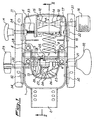
- the support for the chair comprises a fork 1, equipped with base 2 of attachment to the back (not shown).
- the fork oscillates on the transversal pivot 3 by means of the rotation supports 4 with which the body 5 of the support is provided.
- An arm 6 oscillating within the body 5 is rigidly connected to pivot 3, and carries a reaction pivot 7, shown in figures 2 and 3, for spring 8 that regulates the effort necessary for the inclination of the chair.
- Pivot 9 has the function of engaging rack 28 (fig.1), commanded from the outside by means of lever 29 and rod 30 to stop the chair in the desired inclined position.
- Figure 2 also shows a bush 35 joined to reaction pivot 7 and acting as a housing for the mobile extremity 36 of spring 8.
- the spring 8 is joined at the other extremity to the regulation device by means of the spring adjuster according to the present invention.
- Such device has a fixed part 13 rigidly connected with body 5 and a mobile part 10 on which an extremity of spring 8 is coupled.
- the fixed part or the mobile, or both parts has a surface 14 inclined with respect to the axis of spring 8 (which coincides with the right portion of the II-II section line outlined in fig. 1).
- Between the fixed part 13 and mobile part 10 is arranged at least one wedge 12 also having an inclined complementary surface matching the surface of the fixed and/ or mobile part.
- the wedge or wedges are mobile along an axis that is substantially perpendicular to the axis of spring 8. Due to the surface 14 the movement of wedges 12 is converted to the movement of mobile part 10 along the axis of spring 8.
- wedges 12 are slidable on inclined and converging surfaces 14 of fixed part 13 and mobile part 10 under the action of screw 15, which is operated from the outside via the knob 16 and rotating rod 17.
- the inclined surfaces provide a mirror-image angle of inclination with respect to a common reference line.
- the angle ⁇ of inclination of the surfaces (fig.1) is between 85 and 65 degrees and is preferably around 80 degrees.
- the device according to the invention comprises means also to regulate the so-called "zero position,” or starting position, of the inclination.
- the oscillating arm 6 is engaged by means of the slot 18 with the nose 19 of a spacer 20.
- the nose 19 has a side prominence 25 and is transversely mobile on pivot 21, operated from the outside by means of lever 22.
- the spacer is in contact with shelf 26 of the boss 27 attached to the chair support column 24.
- lever 22 also commands the finger lever 23 driving the damper, adjustable in height, located in the chair support column 24.
- the support mechanism for chair presents, finally, L-shaped irons 31 for fixing the seat (not shown). Irons 31 are coupled in an oscillating way via pivots 32 and 33 to fork 1 and to body 5; pivot 33 is controlled from the outside via knob M.
- the L-shaped irons have slots 34 to allow the horizontal shift of the seat with respect to the back.
- the support according to the invention operates as follows: the user, acting on knob 16 and, therefore, on screw 15 brings together or separates wedges 12 of the mechanism: the position of reaction of spring 8 is thus consequently modified, changing the elastic characteristics and therefore the setting. More particularly, in the configuration shown in Figures 1 and 2 the wedges 12 are at their maximum distance and spring 8 is in its widest configuration (i.e. set for the least effort of oscillation). Rotating knob 16 and screw 17 two wedges 12 are drawn together and simultaneously mobile part 10 is moved away from fixed part 13, compressing spring 8 as shown in Fig. 3. In this configuration spring 8 is set for a greater oscillation force.
- the rotation action of the user is mediated by the inclined surfaces 14 of the wedges and of the fixed part 10 and mobile part 13 of the mechanism: this action is smoother, both in terms of the direct effort on the part of the user and in the search for a position more suited to his requirements.
- the angle ⁇ of the inclination of the surfaces can reach 85 degrees giving a strong amplification effect of the fineness of regulation and smootness of actuation.
- the regulation of the starting position of the oscillation is achieved by shifting spacer 20 transversely to the support for the oscillating chair upon pressure on pivot 21 through the lever 22.
- the spacer has two positions: the first, corresponding to Figures 1 and 2, where the nose 19 is housed in the slot 18 in oscillating arm 6, and a second position, visible in figure 3, where nose 19 leans externally against said arm 6, after a translation of pivot 21 toward lever 22.
- the second position is attainable after the user has inclined the chair so as to allow the disengagement of nose 19 from slot 18 and permit the translation of pivot 21.
- the horizontal regulation of the seat position is achieved by operating knob M which controls the spring loaded disengagement pivot 33 and the L-shaped irons can then run with their slots 34 on the pivots 32 and 33 of fork 1 and body 5.
- knob M controls the spring loaded disengagement pivot 33 and the L-shaped irons can then run with their slots 34 on the pivots 32 and 33 of fork 1 and body 5.
- Inclined surfaces 14, other than flat as shown in the Figures could be achieved by constant curvature, cylindrical, or varying, elliptical or with other types of curve, for determine a variation in behavior on the basis of the position of the interposed wedges, with the object of compensating the increase of the elastic reaction of the spring during compression.
Landscapes
- Health & Medical Sciences (AREA)
- Dentistry (AREA)
- General Health & Medical Sciences (AREA)
- Chairs Characterized By Structure (AREA)
- Chairs For Special Purposes, Such As Reclining Chairs (AREA)
- Chair Legs, Seat Parts, And Backrests (AREA)
Applications Claiming Priority (2)
| Application Number | Priority Date | Filing Date | Title |
|---|---|---|---|
| IT1998MI000894A IT1306230B1 (it) | 1998-04-27 | 1998-04-27 | Supporto inclinabile per sedia |
| ITMI980894 | 1998-04-27 |
Publications (2)
| Publication Number | Publication Date |
|---|---|
| EP0956793A2 true EP0956793A2 (de) | 1999-11-17 |
| EP0956793A3 EP0956793A3 (de) | 2001-01-17 |
Family
ID=11379898
Family Applications (1)
| Application Number | Title | Priority Date | Filing Date |
|---|---|---|---|
| EP99107348A Withdrawn EP0956793A3 (de) | 1998-04-27 | 1999-04-21 | Verschwenkbare Stütze für einen Stuhl |
Country Status (3)
| Country | Link |
|---|---|
| US (1) | US20010013569A1 (de) |
| EP (1) | EP0956793A3 (de) |
| IT (1) | IT1306230B1 (de) |
Cited By (4)
| Publication number | Priority date | Publication date | Assignee | Title |
|---|---|---|---|---|
| WO2006026363A2 (en) | 2004-08-26 | 2006-03-09 | L & P Property Management Company | J-back adjustment mechanism |
| WO2006106380A1 (en) * | 2005-04-06 | 2006-10-12 | Donati S.P.A. | Synchronisation mechanism for chairs or armchairs |
| WO2006108536A1 (de) * | 2005-04-13 | 2006-10-19 | Bock 1 Gmbh & Co. Kg | Vorrichtung zur sitzneigeverstellung eines stuhles |
| ITTV20080144A1 (it) * | 2008-11-12 | 2010-05-13 | L & P Property Management Co | Dispositivo di regolazione della spinta di un meccanismo, particolarmente per sedute regolabili |
Families Citing this family (7)
| Publication number | Priority date | Publication date | Assignee | Title |
|---|---|---|---|---|
| CA2446654C (en) * | 2003-10-24 | 2011-12-20 | Ram Machines (1990) Ltd. | Chair spring tension control |
| US7766426B2 (en) * | 2006-08-29 | 2010-08-03 | Ram Machines (1990) Ltd. | Tilt controls for chairs |
| ITMI20070718A1 (it) * | 2007-04-06 | 2008-10-07 | L & P Property Management Co | Dispositivo di regolazione per sedie regolabili e simili. |
| ITMI20070719A1 (it) * | 2007-04-06 | 2008-10-07 | L & P Property Management Co | Dispositivo di inclinazione per un sedile reclinabile. |
| US8498621B2 (en) | 2008-08-20 | 2013-07-30 | At&T Mobility Ii Llc | Cellular device management |
| ITUB20154688A1 (it) * | 2015-10-15 | 2017-04-15 | Co Fe Mo Ind S R L | Meccanismo di oscillazione per sedie regolabile |
| IT201600071468A1 (it) | 2016-07-08 | 2018-01-08 | Co Fe Mo Ind S R L | Meccanismo di oscillazione per sedie |
Family Cites Families (2)
| Publication number | Priority date | Publication date | Assignee | Title |
|---|---|---|---|---|
| JPH0511791Y2 (de) * | 1987-08-24 | 1993-03-24 | ||
| DE4324541A1 (de) * | 1993-07-22 | 1995-01-26 | Trendoffice Bueromoebel | Stuhl, insbesondere Bürostuhl |
-
1998
- 1998-04-27 IT IT1998MI000894A patent/IT1306230B1/it active
-
1999
- 1999-04-21 EP EP99107348A patent/EP0956793A3/de not_active Withdrawn
- 1999-04-27 US US09/299,623 patent/US20010013569A1/en not_active Abandoned
Cited By (6)
| Publication number | Priority date | Publication date | Assignee | Title |
|---|---|---|---|---|
| WO2006026363A2 (en) | 2004-08-26 | 2006-03-09 | L & P Property Management Company | J-back adjustment mechanism |
| EP1799492B1 (de) * | 2004-08-26 | 2019-05-15 | L&P Property Management Company | J-rückenlehnen-verstellmechanismus |
| WO2006106380A1 (en) * | 2005-04-06 | 2006-10-12 | Donati S.P.A. | Synchronisation mechanism for chairs or armchairs |
| US7364233B2 (en) | 2005-04-06 | 2008-04-29 | Donati S.P.A. | Synchronisation mechanism for chairs or armchairs |
| WO2006108536A1 (de) * | 2005-04-13 | 2006-10-19 | Bock 1 Gmbh & Co. Kg | Vorrichtung zur sitzneigeverstellung eines stuhles |
| ITTV20080144A1 (it) * | 2008-11-12 | 2010-05-13 | L & P Property Management Co | Dispositivo di regolazione della spinta di un meccanismo, particolarmente per sedute regolabili |
Also Published As
| Publication number | Publication date |
|---|---|
| IT1306230B1 (it) | 2001-06-04 |
| EP0956793A3 (de) | 2001-01-17 |
| US20010013569A1 (en) | 2001-08-16 |
| ITMI980894A1 (it) | 1999-10-27 |
Similar Documents
| Publication | Publication Date | Title |
|---|---|---|
| US7281764B2 (en) | Tension control mechanism for chair | |
| CN102905579B (zh) | 椅子的靠背用反力机构及安装有该机构的椅子 | |
| US6896329B2 (en) | Chair, in particular office chair | |
| US8025335B2 (en) | Chair | |
| CN107536314B (zh) | 座椅倾斜机构 | |
| US4695093A (en) | Work chair | |
| US4200332A (en) | Adjustable chair | |
| US4270797A (en) | Ergonomic chair | |
| EP0552219B1 (de) | Einrichtung in einem verstellbaren lehnstuhl | |
| EP2725943B1 (de) | Neigungsmechanismus für einen stuhl und stuhl | |
| US20110074197A1 (en) | Chair | |
| US20070057552A1 (en) | Tension adjustment mechanism for a chair | |
| EP0956793A2 (de) | Verschwenkbare Stütze für einen Stuhl | |
| US5005905A (en) | Chair for an office or the like | |
| US7316453B2 (en) | Chair spring tension control | |
| US20060082201A1 (en) | Chair | |
| JPH0531962Y2 (de) | ||
| JPH0646935A (ja) | 椅子の背,座部の連動支持機構 | |
| JP2001057918A (ja) | 椅 子 | |
| GB2264862A (en) | "a chair tilting mechanism" | |
| EP3599938B1 (de) | Gelenksystem für stühle | |
| WO2009127862A1 (en) | Chair back tilt tensioning | |
| EP0956792A2 (de) | Stütze für einen schwingenden oder synchronisierten Stuhl | |
| HK1120710B (en) | Servo mechanism for a seat part, in particular of a chair |
Legal Events
| Date | Code | Title | Description |
|---|---|---|---|
| PUAI | Public reference made under article 153(3) epc to a published international application that has entered the european phase |
Free format text: ORIGINAL CODE: 0009012 |
|
| AK | Designated contracting states |
Kind code of ref document: A2 Designated state(s): AT BE CH CY DE DK ES FI FR GB GR IE IT LI LU MC NL PT SE |
|
| AX | Request for extension of the european patent |
Free format text: AL;LT;LV;MK;RO;SI |
|
| PUAL | Search report despatched |
Free format text: ORIGINAL CODE: 0009013 |
|
| AK | Designated contracting states |
Kind code of ref document: A3 Designated state(s): AT BE CH CY DE DK ES FI FR GB GR IE IT LI LU MC NL PT SE |
|
| AX | Request for extension of the european patent |
Free format text: AL;LT;LV;MK;RO;SI |
|
| AKX | Designation fees paid | ||
| REG | Reference to a national code |
Ref country code: DE Ref legal event code: 8566 |
|
| STAA | Information on the status of an ep patent application or granted ep patent |
Free format text: STATUS: THE APPLICATION IS DEEMED TO BE WITHDRAWN |
|
| 18D | Application deemed to be withdrawn |
Effective date: 20010718 |