EP0956806A1 - Sauggerät zum Ansaugen von Schmutz od.dgl. enthaltendem Sauggut - Google Patents
Sauggerät zum Ansaugen von Schmutz od.dgl. enthaltendem Sauggut Download PDFInfo
- Publication number
- EP0956806A1 EP0956806A1 EP99107788A EP99107788A EP0956806A1 EP 0956806 A1 EP0956806 A1 EP 0956806A1 EP 99107788 A EP99107788 A EP 99107788A EP 99107788 A EP99107788 A EP 99107788A EP 0956806 A1 EP0956806 A1 EP 0956806A1
- Authority
- EP
- European Patent Office
- Prior art keywords
- locking
- suction
- dirt
- suction device
- bearing
- Prior art date
- Legal status (The legal status is an assumption and is not a legal conclusion. Google has not performed a legal analysis and makes no representation as to the accuracy of the status listed.)
- Granted
Links
- 239000000463 material Substances 0.000 title claims description 15
- 238000000926 separation method Methods 0.000 claims abstract description 10
- 239000000428 dust Substances 0.000 claims abstract description 7
- 230000002093 peripheral effect Effects 0.000 claims description 4
- 238000003780 insertion Methods 0.000 claims description 2
- 230000037431 insertion Effects 0.000 claims description 2
- 238000003754 machining Methods 0.000 description 2
- 235000004443 Ricinus communis Nutrition 0.000 description 1
- 240000000528 Ricinus communis Species 0.000 description 1
- 238000013459 approach Methods 0.000 description 1
- 230000000712 assembly Effects 0.000 description 1
- 238000000429 assembly Methods 0.000 description 1
- 238000003801 milling Methods 0.000 description 1
- 238000012986 modification Methods 0.000 description 1
- 230000004048 modification Effects 0.000 description 1
- 239000002245 particle Substances 0.000 description 1
- 238000005192 partition Methods 0.000 description 1
- 238000011144 upstream manufacturing Methods 0.000 description 1
- XLYOFNOQVPJJNP-UHFFFAOYSA-N water Substances O XLYOFNOQVPJJNP-UHFFFAOYSA-N 0.000 description 1
Images


Classifications
-
- A—HUMAN NECESSITIES
- A47—FURNITURE; DOMESTIC ARTICLES OR APPLIANCES; COFFEE MILLS; SPICE MILLS; SUCTION CLEANERS IN GENERAL
- A47L—DOMESTIC WASHING OR CLEANING; SUCTION CLEANERS IN GENERAL
- A47L9/00—Details or accessories of suction cleaners, e.g. mechanical means for controlling the suction or for effecting pulsating action; Storing devices specially adapted to suction cleaners or parts thereof; Carrying-vehicles specially adapted for suction cleaners
-
- A—HUMAN NECESSITIES
- A47—FURNITURE; DOMESTIC ARTICLES OR APPLIANCES; COFFEE MILLS; SPICE MILLS; SUCTION CLEANERS IN GENERAL
- A47L—DOMESTIC WASHING OR CLEANING; SUCTION CLEANERS IN GENERAL
- A47L5/00—Structural features of suction cleaners
- A47L5/12—Structural features of suction cleaners with power-driven air-pumps or air-compressors, e.g. driven by motor vehicle engine vacuum
- A47L5/22—Structural features of suction cleaners with power-driven air-pumps or air-compressors, e.g. driven by motor vehicle engine vacuum with rotary fans
- A47L5/36—Suction cleaners with hose between nozzle and casing; Suction cleaners for fixing on staircases; Suction cleaners for carrying on the back
- A47L5/365—Suction cleaners with hose between nozzle and casing; Suction cleaners for fixing on staircases; Suction cleaners for carrying on the back of the vertical type, e.g. tank or bucket type
Definitions
- the invention relates to a suction device for sucking in dirt or the like.
- suction material for example dust air
- a dirt space for receiving the dirt or the like.
- Lower part of the device an upper part of the device arranged on the lower part, that about a laterally arranged, horizontal pivot axis pivoted on the lower part and from the top of the lower part, covering the dirt space Use position in an open position in which the Dirt room is accessible, can be swung up.
- suction devices are used, for example, in connection with a when machining a workpiece dust-generating hand machine tool used that through a hose line with the suction device is connected so that the accruing during workpiece machining Dust is extracted and collected in the dirt space of the suction device becomes.
- a suction device for dry suction material like dusty air, it can also be a suction device for act wet operation, in particular polluted water is sucked in. To remove dirt or to insert an empty dirt container, the upper part is swung up.
- the invention has for its object a suction device of the beginning to create the kind that is user-friendly and a enables easy assembly.
- the device aggregates, in particular a suction unit for sucking in the suction material and a dirt-retaining separation unit, in Area of the upper part and expediently arranged on this be so that they are locked in the open position
- Upper part are easily accessible and, if necessary, serviced can be held without the upper part being held by hand must become.
- Another advantage is that you can easily remove the top from the bottom, which is why the upper part is simply swung open into its removal position must become.
- the suction device 1 shown in the drawing is used for Suction of dirt or the like containing suction, for example Dust air.
- the suction device 1 can not only for dry suction material but also for wet suction material.
- a lateral connecting piece 2 is arranged on the suction device 1, to the outside of the suction device, only dash-dotted in Fig. 1 indicated hose line 3 can be connected.
- the other The end of the hose line 3 is, for example, with a hand tool like grinder, saw or milling machine connected, in their operation, when the respective workpiece is machined, Dust accumulates.
- a hand tool like grinder, saw or milling machine connected, in their operation, when the respective workpiece is machined, Dust accumulates.
- a handheld machine tool of course another device can also be connected.
- the suction device 1 has a lower device part 4, which has a dirty space 5 contains, in which the contained in the suction material Dirt or the like is collected.
- the dirt space 5 is up open towards.
- a device upper part 6 is arranged on the lower part 4, that about a laterally arranged, horizontal pivot axis 7 is pivotally mounted on the lower part 4, so that Upper part 6 from a top 8 of the lower part 4, the dirt space 5 covering use position (Fig. 1) in an open position (Fig. 2) can be swiveled up, in which the Dirt space 5 is accessible from above, so that the dirt is removed or an empty dirt container can be used.
- a suction unit 9 in the form of a blower is included associated drive motor for sucking the suction material and a Dirt or the like restrained separation unit 10 in the form of a Filter device available.
- the equipment units 9,10 are in the embodiment on the upper part 6 and are arranged in this.
- the upper part 6 is open on its underside.
- the device units 9, 10 mentioned are only by rough outlines indicated.
- the suction unit 9 is arranged on the suction side and is located behind the separation unit when viewed in the direction of flow 10.
- the separation unit 10 is on the upper part 6 above the dirt chamber 5 arranged.
- the dirt space 5 is located in the pivot axis 7 facing away rear device area.
- the suction unit 9 is the separation unit 10 arranged upstream of the swivel axis 7 on the upper part 6 and can in the dirt chamber 5 adjacent to the pivot axis 7 out Immerse space 11 of lower part 4.
- the dirt room 5 and the space 11 just mentioned are through a partition 12 separated from each other.
- the connecting piece 2 is arranged on the lower part 4 of the device.
- the swivel axis 7 is on the same side (front) of the lower part 4 as the connecting piece 2.
- the connecting piece 2 passes through a corresponding recess in the housing of the upper part 6, which allows the pivoting of the upper part 6.
- the lower part 4 contains the suction material within the lower part in the dirt chamber 5 leading suction pipe 13, which in the area of Top 8 of the lower part 4 runs.
- the connecting piece 2 is arranged. The opposite The end of the suction pipe 13 opens into the dirt space 5.
- the suction device 1 shown is mobile and can be pushed or pulled by hand.
- a pair of front casters 14 on the underside of the suction device and a rear pair of castors 15 are present.
- the upper part 6 In its downward direction on the open upper side 8 of the lower part 4 pivoted position of use, the upper part 6, for example attached to the lower part 4 by latching.
- a locking member 16 arranged on the upper part 6 and one assigned locking recess 17 indicated on the lower part 4.
- the dirt space 5 is accessible. Furthermore, the device assemblies 9, 10 are also accessible, so that, for example, the filter device forming the separation unit 10 can be cleaned.
- the device upper part is 6 in the open position releasably lockable with the lower part 4, so that it remains in the open position. It is understood that the Locking is releasable, so that the upper part 6 in the unlocked state can be pivoted again. It is provided that the upper part 6 beyond the open position in the direction of the use position closing the lower part away into a 3 is pivotable, in which the upper part 6 can be removed from the lower part 4 (Fig. 4).
- the upper part 6 is in accordance with its arrival in the open position Fig. 2 locked automatically with the lower part 4.
- this automatic locking takes place both when swiveling up from the use position as well as when swiveling back from the removal position.
- the locking the upper part 6 with the lower part 4 in the open position Locking device has in the embodiment a locking projection 19 arranged on the upper part 6, the is directed substantially parallel to the pivot axis 7, and a contained on the lower part 4 in a locking section 21, the locking recess 19 associated locking recess 20 on.
- the locking projection 19 is in the substantially parallel to the direction of the pivot axis 7 movable by a spring force. Before the top 6 arrives in the open position, the locking projection 19 slides on Locking section 21, wherein he against the spring force Locking portion 21 is held so that when it reaches the Open position occurs in the locking recess 20.
- suction pipe 13 runs in the area of the upper side 8 of the lower part 4.
- This suction tube 13 carries the useful Embodiment, the locking portion 21 on the intake manifold 13 is arranged upwards laterally so that their Outside 25 stands tangentially from the suction pipe 13. In this way forms the circular cylindrical peripheral surface of the suction tube 13 a sliding surface arranged below the locking section 21, about the locking projection 19 when pivoting the Upper part 6 from the use position to the open position the outside 25 of the locking section 28 slides.
- the locking projection 19 also has a locking lug 26 on the locking section in the locked state 21 engages behind the locking recess 20.
- the suction pipe 13 is made of plastic.
- the locking section 21 is integrally formed on the suction pipe 13.
- the locking projection is in the embodiment 19 on the upper part 6 and the locking recess 20th arranged on the lower part 4.
- this could also be the other way round be, i.e. the locking projection could on Lower part of the device and the locking recess on the upper part of the device are located.
- the locking projection 19 instead of the locking projection 19 the locking section with the locking recess be deflectable against a spring force.
- both the locking projection and the the locking portion containing the locking recess to arrange elastically movable.
- the Locking projection 19 on a suitably made of plastic existing locking element 27 is arranged, the a locking arm forming the locking projection 19 28 and a spring arm 29 forms.
- the two arms are 28,29 V-like arranged to each other and go from one on the upper part of the device 6 fixed fastening area 30 of the locking element 27 out.
- On the fastening area 30 opposite The locking projection is located at the end of the locking arm 28 19.
- the end facing away from the fastening area 30 the spring arm 29 is supported on the upper part 6 of the device.
- Fig. 7 are the parts of the upper part 6 on which the fastening area 30 is fixed and the spring arm 29 is supported, indicated by dash-dotted lines.
- the fastening area 30 For defining the fastening area 30 this end of the locking element 27 in a Upper part 6 formed recess 31 inserted.
- the Fastening area 30 arranged on the upper part 6 of the device Retaining tabs 32 or the like attacked.
- the locking element 27 does not have to be directly on the device upper part 6 but can, how shown, on one of the equipment, conveniently on Housing of the suction unit 9, be attached.
- the locking element 27 is on the upper part 6 attached that his locking arm 28 against that of spring arm 29 exerted on the upper part 6 supporting spring arm can be pivoted in the direction of arrow 24.
- the spring arm 29 presses the locking arm 28 against arrow 24 towards the Federar m 29 away.
- the mounting arm 28 in the direction opposite arrow 24 against an end stop 33 held on the upper part of the device, which is on the side of the spring arm 29 is located.
- the locking arm 28 is on the Locking projection 19 from a stop bracket 34, which the End stop 33 forming part of the device upper part 6 engages behind.
- the locking element 27 has a plate-like overall Shape, with the spring arm 29 is formed like a tongue. The remaining area of the plate-shaped locking element 27 forms the locking arm 28.
- locking projection located on the lower part 6 of the device could be a locking element 27 corresponding locking element on the lower part of the device be arranged.
- the locking projection 19 operable to release the lock by hand.
- the locking arm 28 is pressed in the direction according to arrow 24, so that the locking projection 19 from the locking recess 20 swings out. Because of the more convenient manageability a recessed grip 35 can be provided on the locking arm 18, against which you press with a finger.
- the device upper part 6 must be removed from the lower part 4 or can be attached to this, a certain pivot position take in.
- the fixed stop 37 stands from that of the locking section 21 facing away from the peripheral side of the intake manifold 13 and is integrally molded on this.
- the pivot stop 38 has in the embodiment, a finger-like longitudinal shape on and extends inwards approximately from the area of the pivot axis 7, so that it is in the removal position of the upper part 6 from below stops at the fixed stop 27.
- the upper part 6 is in its removal position by one in the embodiment in Range raised by 90 °.
- the upper part 6 is on two in the direction the pivot axis 7 spaced apart via a respective pivot bearing device 41 with the lower part of the device 4 removably connected.
- the two swivel bearing devices 41 are located on the two front corners of the device which the front of the device (this is in the embodiment the connecting piece 2) with one device side each connected is. In the drawing is only one of the two identically designed pivot bearing devices 41 shown.
- the second swivel bearing device is located in Figures 1 to 4 congruent with the visible Swivel bearing device below the drawing level.
- the respective pivot bearing device 41 has two on the lower part 4 arranged in the swivel axis direction 7 at a distance from one another Bearing legs 42, 43 on the fork-like upward are directed and end here freely. However, it could also act as a closed arrangement.
- the Swivel bearing device 41 further includes one on the upper part 6 arranged bearing arm 44, which in the connected state engages between the two bearing legs 42, 43.
- the two Bearing legs 42, 43 have on their respective other bearing legs facing inside a circular cylindrical Pivot bearing recess 45, which is coaxial to the pivot axis line 7 are. Of the two pivot bearing recesses 45 is in 8 only the pivot bearing recess of the bearing leg 43 visible.
- Each pivot bearing recess 45 is also a axially directed pivot bearing projection 46 on the bearing arm 44 of the Device upper part 6 assigned. So that the respective pivot bearing projection 46 in the removed position of the upper part of the device 6 inserted into the relevant pivot bearing recess 45 or can be taken from this are the Pivot bearing recesses 45 arranged on their circumference Plug opening 47 accessible from the outside, the one with reference to the diameter of the respective pivot bearing recess 45 smaller width a. Furthermore, the respective one Pivot bearing projection 46 flattened on its circumference so that he in the removal position of the device upper part 6 across Swivel axis direction 7 in the direction of arrows 39 and 40 the associated plug opening 47 fits. In the embodiment the pivot bearing projection 46 has two opposite one another flattened peripheral pages 48, 49. Otherwise it is the pivot bearing projection 46 is circular cylindrical on its circumference with one of the respective pivot bearing recess 45 appropriate diameter formed.
- each Pivot bearing projection 46 into a pivot bearing recess 45 is inserted so that the device upper part 6 with twisting the pivot bearing protrusions 46 in the pivot bearing recesses 45 can pivot.
- the width a of the insertion opening 47 for stepping out the pivot bearing projection 46 concerned is too small, so that the upper part 6 is held securely on the lower part 4. Only in the removal position can the bearing arm 44 with its pulled out or inserted two pivot bearing projections 46 become.
- the arrangement could also be reversed, that the bearing arm with the at least one pivot bearing projection sits on the lower part of the device 4 and the two bearing legs with the at least one pivot bearing recess 45 on the upper part of the device 6 are arranged.
- the bearing arm 44 and the fixed stop 38 are in the embodiment formed by a one-piece plastic element, attached to the device upper part 6 in a suitable manner is.
- a handle 50 is arranged.
- the top of the top instructs the location of the handle 50 a trough 51 so that the Handle 50 is recessed and therefore not after protrudes upwards.
Landscapes
- Engineering & Computer Science (AREA)
- Mechanical Engineering (AREA)
- Nozzles For Electric Vacuum Cleaners (AREA)
Abstract
Description
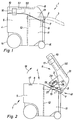
- Fig. 1
- ein erfindungsgemäßes Sauggerät in schematischer Seitenansicht, wobei sich das Oberteil in seiner das Unterteil verschließenden Gebrauchslage befindet,
- Fig. 2
- das Sauggerät nach Fig. 1 in gleicher Darstellungsweise, wobei sich das Geräte-Oberteil in seiner hochgeschwenkten Offenstellung befindet,
- Fig. 3
- wiederum das gleiche Sauggerät in gleicher Darstellungsweise, wobei das Gerät-Oberteil noch weiter in seine Wegnahmestellung aufgeschwenkt ist,
- Fig. 4
- ebenfalls das gleiche Sauggerät in entsprechender Darstellungsweise, wobei das Oberteil vom Unterteil weggenommen ist,
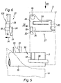
- Fig. 5
- einen insbesondere die Verriegelungseinrichtung in der Wegnahmestellung zeigenden Ausschnitt gemäß Pfeil V in Fig. 3 in vergrößerter Darstellung, wobei das Oberteil und das Unterteil nur strichpunktiert angedeutet sind,
- Fig. 6
- das am Oberteil angeordnete Verriegelungselement der Anordnung nach Fig. 6 in Stirnansicht gemäß Pfeil VI in den Fig. 3 und 5,
- Fig. 7
- die Anordnung nach Fig. 5 in Draufsicht gemäß Pfeil 7 und
- Fig. 8
- den Bereich gemäß Pfeil VIII in Fig. 4 in vergrößerter Schrägansicht in Teildarstellung, so daß eine der beiden Schwenklagereinrichtungen bei vom Unterteil entferntem Oberteil erkenntlich ist.
Claims (13)
- Sauggerät zum Ansaugen von Schmutz od.dgl. enthaltendem Sauggut, beispielsweise Staubluft, mit einem einen Schmutzraum zur Aufnahme des Schmutzes od.dgl. enthaltendem Geräte-Unterteil, einem auf dem Unterteil angeordneten Geräte-Oberteil, das um eine seitlich angeordnete, horizontale Schwenkachse schwenkbar am Unterteil gelagert und aus einer die Oberseite des Unterteils verschließenden, den Schmutzraum überdeckenden Gebrauchsstellung in eine Offenstellung, in der der Schmutzraum zugänglich ist, hochschwenkbar ist, dadurch gekennzeichnet, daß das Oberteil (6) in der Offenstellung lösbar mit dem Unterteil (4) verriegelbar und im entriegelten Zustand über die Offenstellung hinaus in Richtung von der Gebrauchsstellung weg in eine Wegnahmestellung schwenkbar ist, in der das Oberteil (6) vom Unterteil (4) wegnehmbar ist.
- Sauggerät nach Anspruch 1, dadurch gekennzeichnet, daß das Oberteil (6) bei seinem Eintreffen in die Offenstellung zumindest in Richtung von der Gebrauchsstellung her selbsttätig mit dem Unterteil (4) verriegelt wird.
- Sauggerät nach Anspruch 2, dadurch gekennzeichnet, daß am Oberteil (6) oder am Unterteil ein im wesentlichen parallel zur Schwenkachse (7) gerichteter Verriegelungsvorsprung (19) und am jeweils anderen Teil (4) eine Verriegelungspartie (21) mit einer Verriegelungsausnehmung (20) angeordnet ist, wobei der Verriegelungsvorsprung (19) und/oder die Verriegelungspartie im wesentlichen parallel zur Richtung der Schwenkachse (7) entgegen einer Federkraft bewegbar ist, derart, daß vor dem Eintreffen des Oberteils (6) in die Offenstellung der Verriegelungsvorsprung (19) und die Verriegelungspartie (21) aufeinander gleiten und durch die Federkraft gegeneinander gehalten werden und beim Erreichen der Offenstellung der Verriegelungsvorsprung (29) in die Verriegelungsausnehmung (20) eintritt.
- Sauggerät nach Anspruch 3, dadurch gekennzeichnet, daß der Verriegelungsvorsprung (19) und/oder die Verriegelungspartie zum Lösen der Verriegelung mit der Hand betätigbar ist.
- Sauggerät nach Anspruch 3 oder 4, dadurch gekennzeichnet, daß der Verriegelungsvorsprung (19) oder die Verriegelungspartie an einem insbesondere aus Kunststoff bestehenden Verriegelungselement (27)angeordnet ist, das in V-ähnlicher Anordnung zueinander einen Verriegelungsarm (28) und einen Federarm (29) bildet, die einstückig miteinander verbunden sind und von einem am jeweiligen Teil (6) festgelegten Befestigungsbereich (30) des Verriegelungselements (27) ausgehen, wobei der Verriegelungsarm (28) den Verriegelungsvorsprung (19) trägt, beziehungsweise die Verriegelungsausnehmung aufweist und der Federarm (29) sich am jeweiligen Teil (6) abstützt.
- Sauggerät nach einem der Ansprüche 3 bis 5, dadurch gekennzeichnet, daß das Unterteil (4) ein das Sauggut innerhalb des Unterteils (4) in den Schmutzraum (5) führendes Saugrohr (13) enthält, das im Bereich der Oberseite (8) des Unterteils (4) verläuft, und daß die Verriegelungspartie (21) am Saugrohr (13) nach oben hin vorstehend seitlich so angeordnet ist, daß ihre Außenseite (25) tangential vom Saugrohr 13) hochsteht und die Umfangsfläche des Saugrohrs (13) eine Aufgleitfläche bildet, über die der Verriegelungsvorsprung (19) beim Verschwenken des Oberteils (6) aus der Gebrauchsstellung in die Offenstellung auf die Außenseite der Verriegelungspartie (21) gleitet.
- Sauggerät nach einem der Ansprüche 1 bis 6, dadurch gekennzeichnet, daß eine ein Verschwenkendes Oberteils (6) über die Wegnahmestellung hinaus verhindernde Anschlaganordnung (36) vorhanden ist.
- Sauggerät nach Anspruch 7, dadurch gekennzeichnet, daß das Unterteil (4) ein das Sauggut innerhalb des Unterteils (4) in den Schmutzraum (5) führendes Saugrohr (13) enthält, das im Bereich der Oberseite (8) des Unterteils (4) verläuft, und daß das Saugrohr (13) einen Festanschlag (37) trägt, der sich im Schwenkweg eines am Oberteil (6) angeordneten Schwenkanschlags (38) befindet.
- Sauggerät nach einem der Ansprüche 1 bis 8, dadurch gekennzeichnet, daß das Oberteil (6) in seiner Wegnahmestellung um einen im Bereich von 90° liegenden Winkel hochgeschwenkt ist.
- Sauggerät nach einem der Ansprüche 1 bis 9, dadurch gekennzeichnet, daß das Oberteil (6) und das Unterteil (4) über mindestens eine Schwenklagereinrichtung (41) entfernbar miteinander verbunden sind, die zwei am Unterteil (4) oder am Oberteil mit Abstand zueinander angeordnete Lagerschenkel (42, 43) und einen am jeweils anderen Teil (6) angeordneten, zwischen die beiden Lagerschenkel (42, 43) greifenden Lagerarm (44) aufweist und daß die Lagerschenkel (42, 43) oder der Lagerarm mindestens eine Schwenklagerausnehmung (45) aufweisen, der ein axial gerichteter Schwenklagervorsprung (46) am Lagerarm (44) beziehungsweise am jeweiligen Lagerschenkel zugeordnet ist, wobei die Schwenklagerausnehmung (45) über eine an ihrem Umfang angeordnete Stecköffnung (47) mit einer mit Bezug auf den Durchmesser der Schwenklagerausnehmung (45) kleineren Weite (a) von außen her zugänglich ist und der Schwenklagervorsprung (46) an seinem Umfang abgeflacht ist, so daß er in der Wegnahmestellung quer zur Schwenkachsrichtung (7) durch die Stecköffnung (47) paßt.
- Sauggerät nach einem der Ansprüche 1 bis 10, dadurch gekennzeichnet, daß am Oberteil (6) ein Handgriff (50) angeordnet ist.
- Sauggerät nach Anspruch 11, dadurch gekennzeichnet, daß der Handgriff (50) an der Oberseite des Oberteils (6) angeordnet ist.
- Sauggerät nach einem der Ansprüche 1 bis 12, dadurch gekennzeichnet, daß ein Saugaggregat (9) zum Ansaugen des Saugguts und ein den Schmutz zurückhaltendes Trennaggregat (10) am Oberteil (6) angeordnet sind.
Applications Claiming Priority (2)
| Application Number | Priority Date | Filing Date | Title |
|---|---|---|---|
| DE19821705A DE19821705A1 (de) | 1998-05-14 | 1998-05-14 | Sauggerät zum Ansaugen von Schmutz o. dgl. enthaltendem Sauggut |
| DE19821705 | 1998-05-14 |
Publications (2)
| Publication Number | Publication Date |
|---|---|
| EP0956806A1 true EP0956806A1 (de) | 1999-11-17 |
| EP0956806B1 EP0956806B1 (de) | 2004-08-04 |
Family
ID=7867804
Family Applications (1)
| Application Number | Title | Priority Date | Filing Date |
|---|---|---|---|
| EP99107788A Expired - Lifetime EP0956806B1 (de) | 1998-05-14 | 1999-04-20 | Sauggerät zum Ansaugen von Schmutz od.dgl. enthaltendem Sauggut |
Country Status (2)
| Country | Link |
|---|---|
| EP (1) | EP0956806B1 (de) |
| DE (2) | DE19821705A1 (de) |
Cited By (5)
| Publication number | Priority date | Publication date | Assignee | Title |
|---|---|---|---|---|
| EP1656871A3 (de) * | 2004-11-16 | 2007-05-09 | Samsung Gwangju Electronics Co., Ltd. | Staubsauger mit einer Ent- bzw. Verriegellungsvorrichtung für den Staubauffangbehälter |
| CN1330273C (zh) * | 2002-05-08 | 2007-08-08 | 胡佛公司 | 真空吸尘器的污物收集系统 |
| US7594945B2 (en) * | 2005-06-01 | 2009-09-29 | Samsung Gwangju Electronics Co., Ltd. | Dust receptacle fixing/separating apparatus and a cyclone dust collecting device having the same |
| CN102123641A (zh) * | 2008-08-13 | 2011-07-13 | Bsh博施及西门子家用器具有限公司 | 具有打开装置的地面护理设备 |
| US8365350B2 (en) | 2002-11-12 | 2013-02-05 | Black & Decker Inc. | AC/DC hand portable wet/dry vacuum having improved portability and convenience |
Families Citing this family (2)
| Publication number | Priority date | Publication date | Assignee | Title |
|---|---|---|---|---|
| EP1495706B1 (de) | 2003-07-10 | 2013-05-01 | Black & Decker Inc. | Staubsauger |
| DE102013019224A1 (de) | 2013-11-15 | 2015-05-21 | Nilfisk-Advance A/S | Schmutzsauger mit Schwenkklappe |
Citations (6)
| Publication number | Priority date | Publication date | Assignee | Title |
|---|---|---|---|---|
| US3781460A (en) * | 1972-06-13 | 1973-12-25 | Whirlpool Co | Vacuum cleaner construction |
| DE2901203A1 (de) * | 1979-01-13 | 1980-07-24 | Licentia Gmbh | Staubsauger |
| DE3122580A1 (de) * | 1981-06-06 | 1982-12-30 | Progress-Elektrogeräte Mauz & Pfeiffer GmbH & Co, 7000 Stuttgart | Staubsauger |
| DE3302297A1 (de) * | 1983-01-25 | 1984-07-26 | Progress-Elektrogeräte Mauz & Pfeiffer GmbH & Co, 7000 Stuttgart | Staubsauger |
| US4463474A (en) * | 1982-06-07 | 1984-08-07 | Jacobs Paul G | Vacuum cleaner |
| DE4004177A1 (de) * | 1990-02-13 | 1991-08-14 | Miele & Cie | Staubsauger, insbesondere kesselstaubsauger |
-
1998
- 1998-05-14 DE DE19821705A patent/DE19821705A1/de not_active Withdrawn
-
1999
- 1999-04-20 DE DE59910098T patent/DE59910098D1/de not_active Expired - Lifetime
- 1999-04-20 EP EP99107788A patent/EP0956806B1/de not_active Expired - Lifetime
Patent Citations (6)
| Publication number | Priority date | Publication date | Assignee | Title |
|---|---|---|---|---|
| US3781460A (en) * | 1972-06-13 | 1973-12-25 | Whirlpool Co | Vacuum cleaner construction |
| DE2901203A1 (de) * | 1979-01-13 | 1980-07-24 | Licentia Gmbh | Staubsauger |
| DE3122580A1 (de) * | 1981-06-06 | 1982-12-30 | Progress-Elektrogeräte Mauz & Pfeiffer GmbH & Co, 7000 Stuttgart | Staubsauger |
| US4463474A (en) * | 1982-06-07 | 1984-08-07 | Jacobs Paul G | Vacuum cleaner |
| DE3302297A1 (de) * | 1983-01-25 | 1984-07-26 | Progress-Elektrogeräte Mauz & Pfeiffer GmbH & Co, 7000 Stuttgart | Staubsauger |
| DE4004177A1 (de) * | 1990-02-13 | 1991-08-14 | Miele & Cie | Staubsauger, insbesondere kesselstaubsauger |
Cited By (8)
| Publication number | Priority date | Publication date | Assignee | Title |
|---|---|---|---|---|
| CN1330273C (zh) * | 2002-05-08 | 2007-08-08 | 胡佛公司 | 真空吸尘器的污物收集系统 |
| CN100544656C (zh) * | 2002-05-08 | 2009-09-30 | 胡佛公司 | 为真空吸尘器装备多个过滤装置的方法 |
| US8365350B2 (en) | 2002-11-12 | 2013-02-05 | Black & Decker Inc. | AC/DC hand portable wet/dry vacuum having improved portability and convenience |
| EP1656871A3 (de) * | 2004-11-16 | 2007-05-09 | Samsung Gwangju Electronics Co., Ltd. | Staubsauger mit einer Ent- bzw. Verriegellungsvorrichtung für den Staubauffangbehälter |
| AU2005211697C1 (en) * | 2004-11-16 | 2008-04-03 | Samsung Gwangju Electronics Co., Ltd. | Vacuum cleaner |
| US7380308B2 (en) | 2004-11-16 | 2008-06-03 | Samsung Gwangju Electronics Co., Ltd. | Vacuum cleaner |
| US7594945B2 (en) * | 2005-06-01 | 2009-09-29 | Samsung Gwangju Electronics Co., Ltd. | Dust receptacle fixing/separating apparatus and a cyclone dust collecting device having the same |
| CN102123641A (zh) * | 2008-08-13 | 2011-07-13 | Bsh博施及西门子家用器具有限公司 | 具有打开装置的地面护理设备 |
Also Published As
| Publication number | Publication date |
|---|---|
| EP0956806B1 (de) | 2004-08-04 |
| DE19821705A1 (de) | 1999-11-18 |
| DE59910098D1 (de) | 2004-09-09 |
Similar Documents
| Publication | Publication Date | Title |
|---|---|---|
| DE69507836T2 (de) | Filteranordnung für einen staubsauger | |
| EP0277628B1 (de) | Saugreinigungswerkzeug | |
| DE69807752T2 (de) | Staubsauger | |
| DE102004024888B4 (de) | Wirbelungs-Staubsammelvorrichtung und Staubsauger mit einer solchen Staubsammelvorrichtung | |
| DE10240632B4 (de) | Anschluss- bzw. Verbindungsanordnung eines Staubsaugers und eine solche Anschluss- bzw. Verbindungsanordnung aufweisender Staubsauger | |
| DE10124220C2 (de) | Hilfssaugrohr-Anordnung für einen Staubsauger | |
| EP1844691B1 (de) | Vorrichtung zum lösbaren Befestigen eines Staubfilterbeutels in einem staubsaugenden Gerät | |
| DE19522349C2 (de) | Staubsauger für Doppelbetrieb | |
| DE19750543A1 (de) | Tragbares Sauggerät | |
| EP0280831A1 (de) | Filtergerät, insbesondere an Staubsauger | |
| DE10240621A1 (de) | Staubsauger mit einer Wirbelungs-Staubsammelvorrichtung | |
| DE102011107319B4 (de) | Flachwischer und Trägerplatte dafür | |
| EP0956806B1 (de) | Sauggerät zum Ansaugen von Schmutz od.dgl. enthaltendem Sauggut | |
| DE20312836U1 (de) | Saugdüse für ein Saugreinigungsgerät | |
| DE60201838T2 (de) | Staubsauger | |
| EP1247612A1 (de) | Handwerkzeugmaschine mit Staubabsaugung | |
| DE102019123150B4 (de) | Staubfilterbeutel | |
| DE202005002979U1 (de) | Sauggerät | |
| DE29801234U1 (de) | Sauggerät zum Ansaugen von Schmutz o.dgl. enthaltendem Sauggut | |
| DE29814547U1 (de) | Reinigungsvorrichtung für ein Faltenfilter in einem Sauggerät | |
| DE20311505U1 (de) | Staubabsauggerät | |
| DE2227935A1 (de) | Sauggeraet insbesondere fuer industrielle zwecke | |
| EP0711526B1 (de) | Anschlussstutzen für einen Staubsauger | |
| DE19654770B4 (de) | Filtereinrichtung für gasförmige Medien | |
| EP1642521B1 (de) | Staubfilterbox für einen Staubsauger, insbesondere Bodenstaubsauger und Staubsauger mit einer derartigen Staubfilterbox |
Legal Events
| Date | Code | Title | Description |
|---|---|---|---|
| PUAI | Public reference made under article 153(3) epc to a published international application that has entered the european phase |
Free format text: ORIGINAL CODE: 0009012 |
|
| AK | Designated contracting states |
Kind code of ref document: A1 Designated state(s): DE FR GB IT |
|
| AX | Request for extension of the european patent |
Free format text: AL;LT;LV;MK;RO;SI |
|
| 17P | Request for examination filed |
Effective date: 19990922 |
|
| AKX | Designation fees paid |
Free format text: DE FR GB IT |
|
| RAP1 | Party data changed (applicant data changed or rights of an application transferred) |
Owner name: TTS TOOLTECHNIC SYSTEMS AG & CO. KG |
|
| 17Q | First examination report despatched |
Effective date: 20030701 |
|
| GRAP | Despatch of communication of intention to grant a patent |
Free format text: ORIGINAL CODE: EPIDOSNIGR1 |
|
| GRAS | Grant fee paid |
Free format text: ORIGINAL CODE: EPIDOSNIGR3 |
|
| GRAA | (expected) grant |
Free format text: ORIGINAL CODE: 0009210 |
|
| AK | Designated contracting states |
Kind code of ref document: B1 Designated state(s): DE FR GB IT |
|
| REG | Reference to a national code |
Ref country code: GB Ref legal event code: FG4D Free format text: NOT ENGLISH |
|
| REF | Corresponds to: |
Ref document number: 59910098 Country of ref document: DE Date of ref document: 20040909 Kind code of ref document: P |
|
| GBT | Gb: translation of ep patent filed (gb section 77(6)(a)/1977) |
Effective date: 20040909 |
|
| PLBE | No opposition filed within time limit |
Free format text: ORIGINAL CODE: 0009261 |
|
| STAA | Information on the status of an ep patent application or granted ep patent |
Free format text: STATUS: NO OPPOSITION FILED WITHIN TIME LIMIT |
|
| ET | Fr: translation filed | ||
| 26N | No opposition filed |
Effective date: 20050506 |
|
| PGFP | Annual fee paid to national office [announced via postgrant information from national office to epo] |
Ref country code: FR Payment date: 20120511 Year of fee payment: 14 |
|
| REG | Reference to a national code |
Ref country code: FR Ref legal event code: ST Effective date: 20131231 |
|
| PG25 | Lapsed in a contracting state [announced via postgrant information from national office to epo] |
Ref country code: FR Free format text: LAPSE BECAUSE OF NON-PAYMENT OF DUE FEES Effective date: 20130430 |
|
| PGFP | Annual fee paid to national office [announced via postgrant information from national office to epo] |
Ref country code: DE Payment date: 20150205 Year of fee payment: 17 |
|
| REG | Reference to a national code |
Ref country code: DE Ref legal event code: R119 Ref document number: 59910098 Country of ref document: DE |
|
| PG25 | Lapsed in a contracting state [announced via postgrant information from national office to epo] |
Ref country code: DE Free format text: LAPSE BECAUSE OF NON-PAYMENT OF DUE FEES Effective date: 20161101 |
|
| PGFP | Annual fee paid to national office [announced via postgrant information from national office to epo] |
Ref country code: IT Payment date: 20170420 Year of fee payment: 19 |
|
| PGFP | Annual fee paid to national office [announced via postgrant information from national office to epo] |
Ref country code: GB Payment date: 20180313 Year of fee payment: 20 |
|
| PG25 | Lapsed in a contracting state [announced via postgrant information from national office to epo] |
Ref country code: IT Free format text: LAPSE BECAUSE OF NON-PAYMENT OF DUE FEES Effective date: 20180420 |
|
| REG | Reference to a national code |
Ref country code: GB Ref legal event code: PE20 Expiry date: 20190419 |
|
| PG25 | Lapsed in a contracting state [announced via postgrant information from national office to epo] |
Ref country code: GB Free format text: LAPSE BECAUSE OF EXPIRATION OF PROTECTION Effective date: 20190419 |