EP0956902B1 - Dispositif de montage de couteaux sur l'arbre coupant d'un appareil désintégrateur - Google Patents
Dispositif de montage de couteaux sur l'arbre coupant d'un appareil désintégrateur Download PDFInfo
- Publication number
- EP0956902B1 EP0956902B1 EP99109456A EP99109456A EP0956902B1 EP 0956902 B1 EP0956902 B1 EP 0956902B1 EP 99109456 A EP99109456 A EP 99109456A EP 99109456 A EP99109456 A EP 99109456A EP 0956902 B1 EP0956902 B1 EP 0956902B1
- Authority
- EP
- European Patent Office
- Prior art keywords
- groove
- machine according
- shredding machine
- cutting
- shaft
- Prior art date
- Legal status (The legal status is an assumption and is not a legal conclusion. Google has not performed a legal analysis and makes no representation as to the accuracy of the status listed.)
- Expired - Lifetime
Links
- 239000004033 plastic Substances 0.000 claims description 8
- 229920003023 plastic Polymers 0.000 claims description 8
- 239000002184 metal Substances 0.000 claims description 6
- QNRATNLHPGXHMA-XZHTYLCXSA-N (r)-(6-ethoxyquinolin-4-yl)-[(2s,4s,5r)-5-ethyl-1-azabicyclo[2.2.2]octan-2-yl]methanol;hydrochloride Chemical compound Cl.C([C@H]([C@H](C1)CC)C2)CN1[C@@H]2[C@H](O)C1=CC=NC2=CC=C(OCC)C=C21 QNRATNLHPGXHMA-XZHTYLCXSA-N 0.000 claims description 5
- 239000000919 ceramic Substances 0.000 claims description 4
- 230000007423 decrease Effects 0.000 claims description 4
- 239000007787 solid Substances 0.000 claims description 2
- 230000000284 resting effect Effects 0.000 claims 1
- 239000000463 material Substances 0.000 description 14
- 239000002023 wood Substances 0.000 description 4
- 239000002699 waste material Substances 0.000 description 3
- 206010016761 Flat chest Diseases 0.000 description 1
- 239000003795 chemical substances by application Substances 0.000 description 1
- 238000005516 engineering process Methods 0.000 description 1
- 239000000835 fiber Substances 0.000 description 1
- 238000005058 metal casting Methods 0.000 description 1
- 238000000465 moulding Methods 0.000 description 1
- 238000004064 recycling Methods 0.000 description 1
- 230000003014 reinforcing effect Effects 0.000 description 1
- 238000009420 retrofitting Methods 0.000 description 1
- 238000004804 winding Methods 0.000 description 1
Images



Classifications
-
- B—PERFORMING OPERATIONS; TRANSPORTING
- B02—CRUSHING, PULVERISING, OR DISINTEGRATING; PREPARATORY TREATMENT OF GRAIN FOR MILLING
- B02C—CRUSHING, PULVERISING, OR DISINTEGRATING IN GENERAL; MILLING GRAIN
- B02C18/00—Disintegrating by knives or other cutting or tearing members which chop material into fragments
- B02C18/06—Disintegrating by knives or other cutting or tearing members which chop material into fragments with rotating knives
- B02C18/16—Details
- B02C18/18—Knives; Mountings thereof
-
- B—PERFORMING OPERATIONS; TRANSPORTING
- B02—CRUSHING, PULVERISING, OR DISINTEGRATING; PREPARATORY TREATMENT OF GRAIN FOR MILLING
- B02C—CRUSHING, PULVERISING, OR DISINTEGRATING IN GENERAL; MILLING GRAIN
- B02C18/00—Disintegrating by knives or other cutting or tearing members which chop material into fragments
- B02C18/06—Disintegrating by knives or other cutting or tearing members which chop material into fragments with rotating knives
- B02C18/14—Disintegrating by knives or other cutting or tearing members which chop material into fragments with rotating knives within horizontal containers
- B02C18/145—Disintegrating by knives or other cutting or tearing members which chop material into fragments with rotating knives within horizontal containers with knives spaced axially and circumferentially on the periphery of a cylindrical rotor unit
Definitions
- the invention relates to a Shredding machine with one Knife seat arrangement on one bladeshaft the Shredding machine according to the generic term of claim 1.
- a comminution machine with which the invention is concerned and which is shown in FIG. 16 is from DE 42 42 740 A1 known and serves to shred wood, metal parts, plastics, Garbage and other waste.
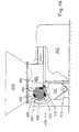
- the shredding machine 101 consists essentially of one Material hopper 102, a loading unit 103 and one Comminution tool 104.
- the three machine components 102, 103, 104 are releasably connected to one another by flange connections and in the assembled state form a loading room 105.
- In the loading room 105 reaches into the Feeding unit 103 opposite lower area cutting shaft 106 driven by an electric motor.
- the Cutting shaft 106 is octagonal or polygonal and equipped with a variety of cutting tools 107.
- the Cutting tools 107 are distributed around the circumference in a thread-like manner arranged attached to the cutting shaft 106 and stand with a first cutting plate 108 and one as a scraper bar 109 serving second insert.
- the top the first cutting plate 108 is also part of the bottom of the Loading space 105.
- a perforated screen 111 attached to reinforcing rings 110.
- a collecting container is located below the perforated sieve 111 112, at its lowest point to remove the shredded Material a screw conveyor 113 is arranged.
- Fig. 17 is a partial perspective view of the cutting shaft 106 viewed from the loading area 105.
- the Cutting shaft 106 has a plurality of cutting tools 107 on, the thread-like mounted on the cutting shaft 106 are arranged. The cutting tools 107 sit in the in the Cutting shaft 106 made recesses 129.
- the recesses 129 extend from a first edge 140 of the cutting shaft 106 to the second edge following in the direction of rotation 141.
- the sole 142 of the recesses 129 deepens on a cutting shaft surface 139 evenly over its entire Longitudinal extent.
- the sole 142 or the contact area 131 forms a right angle with the contact surface 130.
- the Height of the contact surface 131 between the second edge 141 and Sole 142 corresponds to the diagonal extension of a cutting tool 107th
- Such a shredding machine is also in the brochure "Holzmag shredding technology" from Holzmag AG.
- the Cutting tools are rhombic blocks in cross section, which in essentially V-shaped grooves on the circumference of the shaft are distributed, are arranged.
- the grooves are made with cone cutters introduced into the shaft, which is why the one located in the shaft End of the groove is semicircular.
- the Cutting tools that have a flat rhombic face and one have a flat rhombic back surface, need to be impact-resistant to sit in the grooves, a flat surface on the back of the knife.
- semicircular arch-shaped contact elements inserted in the semicircular or semicylindrical groove ends and welded to the material of the shaft.
- the object of the invention is to provide a knife seat arrangement on a To create cutting shaft with the easily different Requirements for the cutting work of the cutting shaft can be mastered.
- Knife system elements can be used loosely in the rear end area of the groove are and can be stored in bulk.
- the knife system elements or stop elements are screwed into the knife seat Cutting tool kept radially covered and also centered by the knife back of the cutting tool.
- the contact surface or the contact element can one over the Wave protruding contour, which preferably to the Contour of the knife is adjusted so that the knife on his entire knife back surface supported by the contact element becomes.
- the knife system elements according to the invention are like the knives easily and quickly interchangeable, so that it can be used with other knives exchanged with correspondingly adapted knife system elements can be.
- a cutting shaft can also be equipped in this way be that at a predetermined maximum drive power can be optimally designed for the material to be shredded.
- a cutting shaft is provided with the same drive power matched to the material to be shredded be that of the thread-like on the circumference of the cutting shaft distributed cutting tools at certain points Removed cutting tools and cover elements according to the invention be replaced, which cover the knife seat like a lid. This enables the number of cutting tools to be reduced or increased with constant driving force of the cutting welie, d. that is, the torque of the cutting shaft is different Knife numbers distributed and thus adapted to the wood chips.
- the inventive Cover elements ensure that there are in the knife seats no wood chips accumulate and the knife seats become dirty or dirty filamentous wood chips in the area of the free knife seats around the Wave winds without being cut. With hard material to be cut the cover elements ensure that the knife seat grooves are not to be damaged.
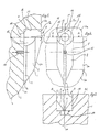
- a cutting shaft 1 for receiving cutting knives or cutting tools is, for example, a cutting shaft 1 with a polygonal cross section. Due to the polygonal cross section flat surfaces 2 are formed, which have edges 3 abut, the edges 3 parallel to a longitudinal axis the shaft 1 running on the circumference of the polygonal cutting shaft 6 are preferably arranged regularly distributed. At the extent the cutting shaft 1 are wound like a thread, equally or regularly distributed knife seats 4 introduced.
- the knife seats 4 are funnel-shaped grooves 5 with a flat cross section Groove bottom 6. The groove bottom 6 or the grooves 5 run as secants from a surface 2 into the cutting shaft 1.
- the groove 5 begins approximately in the transverse center of a surface 2a, extends over the entire width of the next surface 2b and ends approximately in the center of the next but one area 2c. Through the secantial Arrangement of the groove bottom, the groove is from the starting surface 2a down to the end surface 2c.
- the funnel-shaped in cross section The groove ends in the area of the surface 2c with a semi-cylindrical one rounded end 5a.
- the groove 5 has a funnel shape Area from the end area 5a the flat groove bottom 6 and from flat groove bottom 6 tangentially upward, short walls 7, so that the groove 5 above the groove bottom 6 a Rectangular or square groove is. Widened by the short walls 7 the groove with sloping walls 8.
- the groove 5 has a constant height. From the edge 3 between the surface 2c and the surface 2b takes the groove depth successively up to the edge 3 between the surface 2b and the surface 2a from, so that the height of the wall sections 9 of the groove 5 always becomes smaller until the wall sections 9 in the region of the edge 3 disappear between the surfaces 2b and 2a. The depth or Height of the groove 5 increases from the edge 3 between the surface 2b and surface 2a until the groove bottom exits surface 2a further and reinforced by the inclination of surface 2a to surface 2b from.
- the bore 10 is used Includes a mounting screw (not shown) for cutting tools.
- the groove is from the upper surface 2c to formed at the level of the groove bottom 6 as a cylindrical bore 12, so that the groove 5 in the area of the end 5a to the surface 2c has vertical, semi-cylindrical wall 13.
- Neighboring too the walls 8, facing the groove exit of the groove 5, are on both sides the transverse center axis 14 of the groove 5 and adjacent to the wall 13 in the plan view cylindrical shell-shaped walls 15 trained.
- the flat groove bottom 6 ends in one Circular disc-shaped groove bottom 16. Axially aligned with the bore 12 is a cylindrical recess or bore in the bottom 16 17 introduced.
- a stop element or contact element 20 has a cylindrical base plate 21 with a circular disc Cylinder bottom wall and a cylinder jacket wall 23 on.
- a semi-cylindrical one extends from the base plate 21 Section 24 of body 20 away from footplate 21.
- the semi-cylindrical section 24 has a flat chest surface 25 and a jacket wall or back surface that is semicircular in cross section 26 on.
- the flat surface or wall 25 is aligned an axial longitudinal center plane of the base plate 21, the radius the cylinder wall 26 is larger than the radius of the Shell wall 23 of the base plate 21, so that the cylindrical section 24 over one half of the cylindrical base plate 21 a Level 27 survives training.
- the jacket wall 20 of the area 24 tapers in the form of a conical wall 28 up to a tip 29 so that the flat wall 25 is opposite the Base plate 21 inverted V-shaped to the tip 29, an edge 30 training tapered.
- the foot plate 21 corresponds to the bore 17 and fits form-fitting into it, on the top it closes with the Groove bottom 6.
- the jacket wall 26 corresponds to the bore wall 13, so that the stop element 20 in the end region 5a the groove 5 can be arranged, the base plate in the bore 17th rests and the cylinder wall 26 on the bore wall 13 positively is applied.
- Step 27 rests on the surface in a form-fitting manner 16th
- a cutting tool 35 to be arranged in the groove is a Cross section of rhombic elongated block 35 with a lower one in the groove 5 facing longitudinal edge 36, an upper longitudinal edge 37, two lateral longitudinal edges 38 and four are identical to one another angled surfaces 39.
- the rhombus forms one from the groove facing cutting tool face 40 and one to the groove end 5a facing cutting tool back surface 41.
- the areas 39 and the surface 40 form an inverted V-shaped, after outside-facing cutting edge 42. From edge 37 to edge 36 runs approximately in the longitudinal center of the cutting tool introduced a bore 45 which in the region of the edge 37 has a wide bore area 45a which coincides with a step 46 narrows to a narrower bore area 45b.
- the projection 21 is included this embodiment over the entire surface positively on the lower inclined surfaces and the edge 36 of a cutting tool. This allows centering when the cutting tool is inserted or alignment of the stop element can be achieved.
- the edge 30 of the stop element 20 can be shaped accordingly be so that the cutting tool in the area of the longitudinal edge 37 adjacent surface 39 is supported over the entire surface of the stop element becomes.
- the stop element 20 can - matched to the material of the Cutting tool - made of hard metal, metal, ceramics or the like consist. It can also be used for different cutting contours of the cutting tools different stop elements 20 are used, which when replacing the knife with be replaced. On the back surface of the stop element can also be formed projections, which in corresponding corresponding recesses of the round end wall the groove fit, so that the stop elements are radial are secured.
- the stop elements are easily removable. This allows the Stop elements can be easily removed if damaged.
- the stop elements on the different Cutting tool shapes or materials coordinated and with the Knives can be used together. It is also an advantage that the stop elements are not damaged must be welded out.
- a cutting shaft 201 for receiving cutting knives or Cutting tools for example a cutting shaft with a polygonal cross section. Due to the polygonal cross section flat surfaces 202 are formed, which abut with edges 203, the edges 203 parallel to a longitudinal axis of the shaft 201 preferably running on the circumference of the polygonal cutting shaft 206 are regularly distributed.
- Knife seats 204 are funnel-shaped grooves 205 with a flat cross section Groove bottom 206. The groove bottom 206 or the grooves 205 run as Secants from a surface 202 into the cutting shaft 201.
- the groove begins approximately in the transverse center of a surface 202a, extends over the entire width of the next surface 202b and ends approximately in the center of the area after next 202c. Due to the secant arrangement of the groove base, the groove of the starting surface 202a to the end surface 202c lower.
- the in Cross-section funnel-shaped groove ends in the area of surface 202c with a semi-conical, rounded end 205a.
- the Groove 205 has the flat groove bottom 206 and itself in this area Short, tangentially upwardly extending from the flat groove bottom 206 Walls 207 so that the groove 205 above the groove bottom 206 is a rectangular or square groove. From the short walls 207 the groove widens with sloping walls 208.
- the sloping walls 208 are tangential, straight walls 209 to the surface of the cutting shaft 201 or the surface 202c.
- the groove 205 has a constant one Height up. From edge 203 between surface 202c and the Surface 202b successively takes up the groove depth up to edge 203 of surface 202b and surface 202a decreases and decreases from that Edge 203 between surface 202b and surface 202a to Exit of the groove bottom on surface 202a again by the inclination from surface 202a to surface 202b.
- the sloping walls 208 serve as supports for cutting tools.
- the area 202b is perpendicular to the groove bottom 206 a hole 210 is made in the groove bottom. Bore 210 is used to hold a fastening screw for cutting tools.
- the cover element 212 according to the invention is solid, for example made of metal or a ceramic and has walls corresponding to the inclined walls 208 213, which abut on a common edge 214.
- the edge 214 rests when the cover element 212 in the Groove 205 is arranged between the short walls 207 and is preferably slightly spaced from the groove bottom 206.
- the remaining Surfaces of the cover element 212 correspond to the groove formed so that in the area of the surface 202c or the groove end 205a, the cover element 212 has a semicircular funnel shape and along the semicircular funnel-shaped end 215 the groove 205 tapers with the cover member 212 outward facing surfaces 216a, 216b oriented at an angle to one another and 216c which mates with surfaces 202a, 202b and 202c align or complete the polygonal cutting shaft 201 and cover the groove like a lid.
- the cover element 212 is aligned with the bore 210 Bore 218, which from surface 216b perpendicular to the edge 214 ago introduced into the cover element 212 and from another area 218a with a step 219 to a narrower Area 218b is narrowed.
- Through hole 218 or hole 218 is a threaded bolt which can be plugged into the threaded hole 210 of the shaft can be screwed to cover element 212 in the Arrange groove firmly.
- cover element 212 in a further embodiment of the cover element (FIG. 14 to 16) is the cover element 212 as a hollow profile in the form of a double angled plate 220 formed, with the Bend three surfaces 221a, 221b and 221c are formed which abut on fold edges 222.
- the external form of the Plate 220 corresponds to the shape of the groove 205 and the Shaft 201, adjacent to surfaces 202a, 202b, 202c, so that in in the inserted state 205 of the cover 212 Plate 220 closes positively on the outside.
- the plate 220 points towards the bore 210 in the groove bottom 206 cylindrical projection 225, which in the area of the oblique Walls 208 of the groove 205 with corresponding to the walls 208 inclined support walls 226 is formed.
- a bore in the area of the molding 225 218 introduced for receiving a screw bolt is also a bore in the area of the molding 225 218 introduced for receiving a screw bolt.
- Fig. 15 is the longitudinal course a stiffening rib on the underside of the cover element 212 227 and a transverse to this in the area of bore 218 Cross stiffening rib 228 arranged.
- the freed four knife seats or grooves are with inventive Cover elements covered like a lid, being from
- the advantage is that the cover elements prevent clippings accumulates in the grooves or clippings that are difficult to cut, such as carpets, on exposed grooves 205 caught and wrapped around the shaft without being cut become. With hard clippings, the cover elements prevent that the knife seat grooves not equipped with knives through the clippings to be damaged.
- the Cover elements in a particularly simple and easy way, for example can be produced by metal casting.
- cover elements By providing cover elements, it is thus possible a conventional cutting shaft for the different types of material to be cut quick changeover.
- the retrofitting can be done more easily and quickly Achieve wise.
Landscapes
- Engineering & Computer Science (AREA)
- Food Science & Technology (AREA)
- Crushing And Pulverization Processes (AREA)
- Treatment Of Fiber Materials (AREA)
- Knives (AREA)
- Milling Processes (AREA)
Claims (32)
- Machine de fragmentation avec un agencement de siège de couteau sur un arbre de coupe de la machine de fragmentation avec une rainure de siège de couteau (5) et un outil de coupe (35) disposé dedans, l'outil de coupe fixé de manière séparable dans la rainure de siège de couteau reposant avec une surface dorsale plane (25) contre une surface frontale plane d'un élément de butée (20) et l'élément de butée (20) reposant avec une paroi dorsale semi-cylindrique (26) contre une surface côté extrémité formée de manière correspondante de la rainure de siège du couteau (5), caractérisée en ce que l'élément de butée (20) présente, dans la zone du fond de rainure (6) de la rainure de siège de couteau (5), une saillie (21) située en particulier de manière solidaire avec correspondance de forme dans un évidement correspondant du fond de la rainure, orientée vers l'intérieur de l'arbre, ladite saillie s'engageant par endroits sous l'outil de coupe (35) et étant disposée en s'appuyant contre celui-ci, de façon que l'élément de butée (20) soit supporté radialement dans la rainure par l'outil de coupe (35).
- Machine de fragmentation selon la revendication 1, caractérisée en ce que la saillie de l'élément de butée est une semelle cylindrique (21) avec une paroi de fond de cylindre circulaire (22) et une paroi de corps de cylindre (23).
- Machine de fragmentation selon la revendication 1 et/ou 2, caractérisée en ce que la partie semi-cylindrique (24) de l'élément de butée (20) s'étend sur la moitié arrière de la semelle (21), la partie semi-cylindrique (24) présentant la surface frontale plane (25) et la paroi d'enveloppe, respectivement la surface dorsale (26) de forme semi-circulaire en coupe.
- Machine de fragmentation selon l'une des revendications précédentes, caractérisée en ce que la paroi plane (25) est alignée avec un plan médian longitudinal axial de la semelle (21), le rayon de la paroi du corps de cylindre (26) étant plus grand que le rayon de la paroi du corps (23) de la semelle (21), de façon que la partie cylindrique (24) dépasse sur une moitié de la semelle cylindrique (21) en formant un gradin 27.
- Machine de fragmentation selon l'une ou plusieurs des revendications précédentes, caractérisée en ce que la paroi d'enveloppe (20) de la zone (24) se rétrécit de manière opposée à la semelle (21) en forme d'une paroi conique (28) jusqu'à une pointe (29), de façon que la paroi plane (28) se rétrécisse par rapport à la semelle (21) en forme de V inversé vers la pointe (29) en formant une arête (30).
- Machine de fragmentation selon l'une ou plusieurs des revendications précédentes, caractérisée en ce que la semelle (21) repose de manière séparable, de manière solidaire avec correspondance de forme, dans un orifice cylindrique (17) de la rainure du couteau (5), le gradin (27) reposant de manière solidaire avec correspondance de forme contre la surface (16) et la paroi d'enveloppe (26) contre une paroi de rainure (13).
- Machine de fragmentation selon l'une ou plusieurs des revendications précédentes, caractérisée en ce que l'outil de coupe (35) est un bloc de section rhomboïde allongée avec une arête longitudinale inférieure (36) orientée vers le fond de rainure (6) de la rainure (5) et une arête longitudinale supérieure (37), ainsi que deux arêtes longitudinales latérales (38) ainsi qu'une surface frontale d'outil de coupe (40) et une surface dorsale d'outil de coupe (41), l'arête longitudinale (36) reposant sur le fond de rainure (6) et, du côté supérieur, sur la saillie (21).
- Machine de fragmentation selon l'une ou plusieurs des revendications précédentes, caractérisée en ce que l'arête (30) de l'élément de butée (20) se termine par des faces supérieures voisines de l'arête (37) de l'outil de coupe (35).
- Machine de fragmentation selon l'une ou plusieurs des revendications précédentes, caractérisée en ce que l'arête (30) de l'élément de butée (20) présente, dans le cas de surfaces formées en contour (39) de l'outil de coupe (35), un contour identique et se termine avec les surfaces en contour (39) de l'outil de coupe (35).
- Machine de fragmentation selon l'une ou plusieurs des revendications précédentes, caractérisée en ce que la surface frontale (25) de l'élément de butée (20) repose sur toute sa surface contre la surface dorsale (41) de l'outil de coupe (35).
- Machine de fragmentation selon l'une ou plusieurs des revendications précédentes, caractérisée en ce que l'élément de butée (20) est réalisé en métal dur, en métal, en céramique ou en matière plastique.
- Machine de fragmentation selon l'une ou plusieurs des revendications précédentes, caractérisée en ce que des moyens prévus sur la surface dorsale (26) de l'élément de butée (20) peuvent venir en prise avec des moyens correspondants de la paroi de rainure correspondante (13).
- Machine de fragmentation selon l'une ou plusieurs des revendications précédentes, caractérisée en ce que la surface de la semelle (21) ou de la saillie (21), disposée sous l'outil de coupe (35), est formée en dépassant au-dessus du niveau du fond de rainure (6) de la rainure (5) en formant une rainure en forme de V, la rainure en forme de V de la semelle étant conçue de façon que la semelle (21) repose du côté supérieur sur toute sa surface, de manière solidaire avec correspondance de forme, contre les surfaces inclinées inférieures et l'arête longitudinale inférieure (36) d'un outil de coupe (35).
- Machine de fragmentation selon l'une ou plusieurs des revendications 1 à 13, caractérisée en ce que, pour être adaptées à un travail de coupe souhaité, les fraisures de siège du couteau (204) d'un plan radial commun de l'arbre (201) sont équipées de manière régulière d'outils de coupe et que des fraisures de siège de couteau (204) prédéterminées ne sont pas occupées par un outil de coupe et sont recouvertes à la manière d'un couvercle par un élément de recouvrement pouvant être fixé (212).
- Machine de fragmentation selon la revendication 14, caractérisée en ce que les fraisures de siège de couteau (204) sont essentiellement des rainures en forme de V (205) et que l'élément de recouvrement (212) présente des moyens (213, 225) avec lesquels il atteint au moins par endroits une solidarité de forme avec les zones de paroi (208) formant la rainure (205) et présente une surface (216) orientée vers l'extérieur, qui correspond au contour de l'arbre de coupe (201) dans la zone de la rainure (205) et se termine avec la surface de l'arbre de coupe (202).
- Machine de fragmentation selon la revendication 14 et/ou 15, caractérisée en ce que la surface (216) de l'élément de recouvrement (212) est conçue avec des surfaces planes (216a, 216b, 216c) formant des angles les unes avec les autres, qui se terminent par les surfaces planes formant des angles les unes avec les autres d'un arbre de coupe polygonal (201).
- Machine de fragmentation selon l'une ou plusieurs des revendications précédentes, caractérisée en ce que la surface (216) de l'élément de recouvrement (212) est de forme arrondie, en particulier en forme de découpe de corps de cylindre et se termine par la surface d'un arbre de coupe cylindrique (201).
- Machine de fragmentation selon l'une ou plusieurs des revendications précédentes, caractérisée en ce que l'élément de recouvrement (212) est conçu de manière massive, remplissant la fraisure de siège du couteau pratiquement sur toute la surface, et se terminant par la surface de l'arbre de coupe.
- Machine de fragmentation selon l'une ou plusieurs des revendications 14 à 18, caractérisée en ce que l'élément de recouvrement (212) est en métal, en céramique ou en matière plastique.
- Machine de fragmentation selon l'une ou plusieurs des revendications 14 à 19, caractérisée en ce que l'élément de recouvrement (212) présente des parois (213) correspondant aux surfaces (208) délimitant la rainure (205).
- Machine de fragmentation selon l'une ou plusieurs des revendications 14 à 20, caractérisée en ce que l'élément de recouvrement (212) présente un orifice (210) qui est pratiqué dans le sens radial dans l'élément de recouvrement (212) par rapport à la disposition de l'élément de recouvrement (212) sur un arbre (201).
- Machine de fragmentation selon l'une ou plusieurs des revendications 14 à 21, caractérisée en ce que l'élément de recouvrement (212) est conçu comme un profilé creux avec une plaque (220) se terminant avec la surface extérieure de l'arbre, des moyens (225) étant prévus sur la plaque (220), avec lesquels la plaque (220) s'appuie dans la rainure (205) contre les surfaces (208) délimitant la rainure (205).
- Machine de fragmentation selon l'une ou plusieurs des revendications 14 à 22, caractérisée en ce que l'arbre de coupe est en forme de polygone avec une pluralité de surfaces planes (202) formant des angles entre elles.
- Machine de fragmentation selon l'une ou plusieurs des revendications 14 à 23, caractérisée en ce que les sièges de couteaux (204) sont, en coupe, des rainures en forme d'entonnoir (205) avec un fond de rainure (206) plan, le fond de rainure (206) ou les rainures (205) étant disposés comme des sécantes allant d'une surface (202) dans l'arbre de coupe (201).
- Machine de fragmentation selon l'une ou plusieurs des revendications 14 à 24, caractérisée en ce que la rainure (205) commence à peu près dans le milieu transversal d'une surface (202a), s'étend sur toute la largeur de la surface voisine (202b) dans le sens inverse de la rotation et se termine à peu près dans le milieu transversal de la deuxième surface voisine (202c) dans le sens de rotation.
- Machine de fragmentation selon l'une ou plusieurs des revendications 14 à 25, caractérisée en ce que la rainure (205) s'étend de manière sécante à l'axe longitudinal de l'arbre et se creuse à partir d'une surface (202a) de l'arbre polygonal jusqu'à la surface (202c) dans la zone de laquelle la rainure (205) se termine.
- Machine de fragmentation selon l'une ou plusieurs des revendications 14 à 26, caractérisée en ce que la rainure de section en forme d'entonnoir se termine dans la zone de la surface (202c) avec une extrémité arrondie, en forme d'entonnoir en demi-cône (205a).
- Machine de fragmentation selon l'une ou plusieurs des revendications 14 à 27, caractérisée en ce que la rainure (205) présente un fond de rainure plat (206) dans la zone de l'extrémité (205a) et des parois courtes (207) s'étendant à partir du fond de rainure plat (206), perpendiculairement à la surface (202) de l'arbre et au fond de rainure (206), de façon que la rainure (205) soit, au-dessus du fond de rainure (206), de forme rectangulaire ou carrée.
- Machine de fragmentation selon l'une ou plusieurs des revendications 14 à 28, caractérisée en ce que la rainure (205) s'élargit vers l'extérieur, à partir des parois courtes (207), avec des parois inclinées (208), lesdites parois inclinées (208) étant des parois d'appui pour des outils de coupe ou des éléments de recouvrement (212).
- Machine de fragmentation selon l'une ou plusieurs des revendications 14 à 29, caractérisée en ce que des parois droites tangentielles (209) s'étendent, à partir des parois inclinées (208), jusqu'à la surface de l'arbre de coupe (201), respectivement de la surface (202c).
- Machine de fragmentation selon l'une ou plusieurs des revendications 14 à 30, caractérisée en ce que la rainure (205) présente une hauteur constante dans la zone de la surface (202c), la profondeur de rainure diminuant à partir d'une arête (203) entre la surface (202c) et la surface (202b) successivement jusqu'à l'arête (203) entre la surface (202b) et la surface (202a), et la profondeur de la rainure diminue davantage, de l'inclinaison de la surface (202a) par rapport à la surface (202b), à partir de l'arête (203) entre la surface (202b) et la surface (202a), jusqu'à la sortie du fond de rainure (206) sur la surface (202a).
- Machine de fragmentation selon l'une ou plusieurs des revendications 14 à 31, caractérisée en ce qu'un orifice (210) est pratiqué dans le fond de rainure (206), dans la zone de la surface (202b) perpendiculaire au fond de rainure (206).
Priority Applications (1)
| Application Number | Priority Date | Filing Date | Title |
|---|---|---|---|
| DE29924262U DE29924262U1 (de) | 1998-05-12 | 1999-05-11 | Messersitzanordnung an einer Schneidwelle in einer Zerkleinerungsmaschine |
Applications Claiming Priority (4)
| Application Number | Priority Date | Filing Date | Title |
|---|---|---|---|
| DE19821205 | 1998-05-12 | ||
| DE1998121207 DE19821207A1 (de) | 1998-05-12 | 1998-05-12 | Schneidwelle für Zerkleinerungsmaschinen |
| DE1998121205 DE19821205A1 (de) | 1998-05-12 | 1998-05-12 | Messersitzanordnung an einer Schneidwelle in einer Zerkleinerungsmaschine |
| DE19821207 | 1998-05-12 |
Publications (2)
| Publication Number | Publication Date |
|---|---|
| EP0956902A1 EP0956902A1 (fr) | 1999-11-17 |
| EP0956902B1 true EP0956902B1 (fr) | 2003-03-26 |
Family
ID=26046137
Family Applications (1)
| Application Number | Title | Priority Date | Filing Date |
|---|---|---|---|
| EP99109456A Expired - Lifetime EP0956902B1 (fr) | 1998-05-12 | 1999-05-11 | Dispositif de montage de couteaux sur l'arbre coupant d'un appareil désintégrateur |
Country Status (6)
| Country | Link |
|---|---|
| US (1) | US6533200B2 (fr) |
| EP (1) | EP0956902B1 (fr) |
| AT (1) | ATE235317T1 (fr) |
| CA (1) | CA2272009A1 (fr) |
| DE (1) | DE59904688D1 (fr) |
| ES (1) | ES2196669T3 (fr) |
Families Citing this family (6)
| Publication number | Priority date | Publication date | Assignee | Title |
|---|---|---|---|---|
| CN102029212B (zh) * | 2009-10-01 | 2013-11-20 | 株式会社近畿 | 破碎机用旋转刀刃的安装结构以及单轴破碎机 |
| FI122643B (fi) * | 2010-07-07 | 2012-04-30 | Bmh Technology Oy | Murskainroottorin teräpala |
| DE102013217164A1 (de) * | 2013-08-28 | 2015-03-05 | Panel Board Holding Bv | Zerkleinerungsvorrichtung |
| EP3012024B1 (fr) | 2014-10-21 | 2018-10-03 | FOR REC srl | Machine de broyeur de déchets |
| US20170259271A1 (en) * | 2016-03-08 | 2017-09-14 | Imex Sourcing Inc. | Tooth and toothholder for industrial mulching apparatus |
| US10357776B2 (en) * | 2016-09-09 | 2019-07-23 | Comcorp, Inc. | Impact cutter blade and holder system and method |
Family Cites Families (18)
| Publication number | Priority date | Publication date | Assignee | Title |
|---|---|---|---|---|
| US169654A (en) | 1875-11-09 | Improvement in toothed rollers for coal breakers or crackers | ||
| US994264A (en) | 1910-07-28 | 1911-06-06 | Union Twist Drill Co | Slab-milling cutter. |
| US1939660A (en) | 1930-09-26 | 1933-12-19 | Pennsylvania Crusher Co | Replaceaele tooth for crusher rolls and other crushing elements |
| DE930839C (de) | 1951-10-11 | 1955-07-25 | Westfalia Dinnendahl Groeppel | Rotor fuer Schleudermuehlen |
| BE519398A (fr) | 1952-05-19 | |||
| US4561156A (en) | 1983-06-09 | 1985-12-31 | Sun Ting Zui | Roller for sugar cane squeezing mills |
| US4609158A (en) | 1984-04-16 | 1986-09-02 | Midland-Ross Corporation | Composite grinding mill liner |
| EP0266447B1 (fr) | 1986-11-05 | 1990-05-30 | Hans Hench | Dispositif de coupe rotatif, en particulier pour un granulateur de matière plastique |
| DE3742395C1 (de) | 1987-12-15 | 1989-06-15 | Deutscher Sbm Vertrieb Franz W | Rotor fuer eine Prallmuehle |
| EP0344348B1 (fr) * | 1988-06-02 | 1993-12-01 | Hans Hench | Couteaux rotatifs pour la granulation des matériaux plastiques |
| US5044570A (en) * | 1990-05-09 | 1991-09-03 | Montgomery Industries International Inc. | Shaver rotor assembly |
| US5240192A (en) | 1991-01-04 | 1993-08-31 | Tilby Sydney E | Cutting roll with removable blade |
| DE4242740C2 (de) | 1992-12-17 | 1998-09-10 | Holz Metall Abfall Recyclingte | Zerkleinerungsmaschine |
| US5381976A (en) * | 1993-06-11 | 1995-01-17 | The Babcock & Wilcox Company | Replaceable tip hammer |
| DE29504292U1 (de) * | 1995-03-14 | 1996-07-25 | BMH Wood Technology GmbH, 57647 Hirtscheid | Wendeschneidkörper |
| DE29515768U1 (de) * | 1995-10-04 | 1995-12-07 | Holz-, Metall-, Abfall-, Recyclingtechnik Gmbh, 79576 Weil Am Rhein | Schneidwerkzeug für Zerkleinerungsmaschinen |
| US5971305A (en) * | 1997-07-21 | 1999-10-26 | Davenport; Ricky W. | Rotary shredder |
| DE29714130U1 (de) * | 1997-08-07 | 1997-10-09 | Unterwurzacher Patentverwertungsgesellschaft M.B.H., Kuchl | Zerkleinerungsvorrichtung |
-
1999
- 1999-05-11 AT AT99109456T patent/ATE235317T1/de not_active IP Right Cessation
- 1999-05-11 EP EP99109456A patent/EP0956902B1/fr not_active Expired - Lifetime
- 1999-05-11 ES ES99109456T patent/ES2196669T3/es not_active Expired - Lifetime
- 1999-05-11 DE DE59904688T patent/DE59904688D1/de not_active Expired - Lifetime
- 1999-05-12 CA CA002272009A patent/CA2272009A1/fr not_active Abandoned
-
2001
- 2001-03-15 US US09/810,806 patent/US6533200B2/en not_active Expired - Lifetime
Also Published As
| Publication number | Publication date |
|---|---|
| US6533200B2 (en) | 2003-03-18 |
| EP0956902A1 (fr) | 1999-11-17 |
| ES2196669T3 (es) | 2003-12-16 |
| US20010038049A1 (en) | 2001-11-08 |
| ATE235317T1 (de) | 2003-04-15 |
| CA2272009A1 (fr) | 1999-11-12 |
| DE59904688D1 (de) | 2003-04-30 |
Similar Documents
| Publication | Publication Date | Title |
|---|---|---|
| DE69932315T2 (de) | Schneidzahnanordnung | |
| DE68905063T2 (de) | Zerkleinerer. | |
| DE1453328C3 (de) | Schneidmesser für eine mit umlaufenden Messerträger versehene Vorrichtung zur Herstellung von Holzschnitzeln | |
| DE8915534U1 (de) | Zerkleinerungsvorrichtung für Abfälle | |
| EP2679309A2 (fr) | Dispositif de broyage comprenant un rotor de broyage avec lame traversante | |
| EP0387868B1 (fr) | Dispositif de broyage pour déchets de bois | |
| DE4242740C2 (de) | Zerkleinerungsmaschine | |
| EP0956902A1 (fr) | Dispositif de montage de couteaux sur l'arbre coupant d'un appareil désintégrateur | |
| EP0468338B1 (fr) | Appareil de broyage pour matières en vrac fibreuses ou granulaires comme des déchets | |
| EP0956901A1 (fr) | Arbre coupant muni d'éléments coupants pour appareil désintégrateur | |
| DE3908395C2 (de) | Vorrichtung zum Zerkleinern von Rest- und Abfallhölzern | |
| DE2827391C2 (de) | Rotor für eine Zerkleinerungsvorrichtung | |
| AT398711B (de) | Zylindrischer rotor | |
| EP0792728B1 (fr) | Equipement pour le tronçonnage de bois | |
| DE29924262U1 (de) | Messersitzanordnung an einer Schneidwelle in einer Zerkleinerungsmaschine | |
| EP0809533A1 (fr) | Cylindre de broyeur et broyeur equipe d'un tel cylindre | |
| DE19821205A1 (de) | Messersitzanordnung an einer Schneidwelle in einer Zerkleinerungsmaschine | |
| DE3013968A1 (de) | Maschine zur zerkleinerung von ton- oder lehmmaterial | |
| DE19821207A1 (de) | Schneidwelle für Zerkleinerungsmaschinen | |
| DE19634465A1 (de) | Zerkleinerungswerkzeug für Shredder | |
| EP1149631B1 (fr) | Fixation d'outil pour tambour de coupe rotatif | |
| DE9218951U1 (de) | Zerkleinerungsmaschine | |
| DE9204176U1 (de) | Vorrichtung zum Zerkleinern von Holzstücken, insbesondere von Restholz | |
| EP0908238A1 (fr) | Dispositif déchiqueteur de matériaux | |
| DE19515867A1 (de) | Zerkleinerungsmaschine |
Legal Events
| Date | Code | Title | Description |
|---|---|---|---|
| PUAI | Public reference made under article 153(3) epc to a published international application that has entered the european phase |
Free format text: ORIGINAL CODE: 0009012 |
|
| AK | Designated contracting states |
Kind code of ref document: A1 Designated state(s): AT BE CH DE ES FR GB IT LI LU NL PT |
|
| AX | Request for extension of the european patent |
Free format text: AL;LT;LV;MK;RO;SI |
|
| AKX | Designation fees paid |
Free format text: AT BE CH DE ES FR GB IT LI LU NL PT |
|
| 17P | Request for examination filed |
Effective date: 20000529 |
|
| GRAH | Despatch of communication of intention to grant a patent |
Free format text: ORIGINAL CODE: EPIDOS IGRA |
|
| GRAH | Despatch of communication of intention to grant a patent |
Free format text: ORIGINAL CODE: EPIDOS IGRA |
|
| GRAA | (expected) grant |
Free format text: ORIGINAL CODE: 0009210 |
|
| AK | Designated contracting states |
Designated state(s): AT BE CH DE ES FR GB IT LI LU NL PT |
|
| PG25 | Lapsed in a contracting state [announced via postgrant information from national office to epo] |
Ref country code: NL Free format text: LAPSE BECAUSE OF FAILURE TO SUBMIT A TRANSLATION OF THE DESCRIPTION OR TO PAY THE FEE WITHIN THE PRESCRIBED TIME-LIMIT Effective date: 20030326 Ref country code: GB Free format text: LAPSE BECAUSE OF FAILURE TO SUBMIT A TRANSLATION OF THE DESCRIPTION OR TO PAY THE FEE WITHIN THE PRESCRIBED TIME-LIMIT Effective date: 20030326 |
|
| REG | Reference to a national code |
Ref country code: GB Ref legal event code: FG4D Free format text: NOT ENGLISH |
|
| REG | Reference to a national code |
Ref country code: CH Ref legal event code: EP |
|
| REF | Corresponds to: |
Ref document number: 59904688 Country of ref document: DE Date of ref document: 20030430 Kind code of ref document: P |
|
| PG25 | Lapsed in a contracting state [announced via postgrant information from national office to epo] |
Ref country code: LU Free format text: LAPSE BECAUSE OF NON-PAYMENT OF DUE FEES Effective date: 20030511 Ref country code: AT Free format text: LAPSE BECAUSE OF NON-PAYMENT OF DUE FEES Effective date: 20030511 |
|
| PG25 | Lapsed in a contracting state [announced via postgrant information from national office to epo] |
Ref country code: LI Free format text: LAPSE BECAUSE OF NON-PAYMENT OF DUE FEES Effective date: 20030531 Ref country code: CH Free format text: LAPSE BECAUSE OF NON-PAYMENT OF DUE FEES Effective date: 20030531 Ref country code: BE Free format text: LAPSE BECAUSE OF NON-PAYMENT OF DUE FEES Effective date: 20030531 |
|
| PG25 | Lapsed in a contracting state [announced via postgrant information from national office to epo] |
Ref country code: PT Free format text: LAPSE BECAUSE OF FAILURE TO SUBMIT A TRANSLATION OF THE DESCRIPTION OR TO PAY THE FEE WITHIN THE PRESCRIBED TIME-LIMIT Effective date: 20030626 |
|
| NLV1 | Nl: lapsed or annulled due to failure to fulfill the requirements of art. 29p and 29m of the patents act | ||
| GBV | Gb: ep patent (uk) treated as always having been void in accordance with gb section 77(7)/1977 [no translation filed] |
Effective date: 20030326 |
|
| BERE | Be: lapsed |
Owner name: *HOLZ- METALL- ABFALL- RECYCLINGTECHNIK G.M.B.H. Effective date: 20030531 |
|
| REG | Reference to a national code |
Ref country code: ES Ref legal event code: FG2A Ref document number: 2196669 Country of ref document: ES Kind code of ref document: T3 |
|
| ET | Fr: translation filed | ||
| REG | Reference to a national code |
Ref country code: CH Ref legal event code: PL |
|
| PLBE | No opposition filed within time limit |
Free format text: ORIGINAL CODE: 0009261 |
|
| STAA | Information on the status of an ep patent application or granted ep patent |
Free format text: STATUS: NO OPPOSITION FILED WITHIN TIME LIMIT |
|
| 26N | No opposition filed |
Effective date: 20031230 |
|
| REG | Reference to a national code |
Ref country code: FR Ref legal event code: TP |
|
| REG | Reference to a national code |
Ref country code: ES Ref legal event code: PC2A |
|
| PG25 | Lapsed in a contracting state [announced via postgrant information from national office to epo] |
Ref country code: IT Free format text: LAPSE BECAUSE OF NON-PAYMENT OF DUE FEES Effective date: 20090511 |
|
| PGRI | Patent reinstated in contracting state [announced from national office to epo] |
Ref country code: IT Effective date: 20110616 |
|
| REG | Reference to a national code |
Ref country code: DE Ref legal event code: R082 Ref document number: 59904688 Country of ref document: DE Representative=s name: BOEHMERT & BOEHMERT, DE Ref country code: DE Ref legal event code: R082 Ref document number: 59904688 Country of ref document: DE |
|
| REG | Reference to a national code |
Ref country code: DE Ref legal event code: R082 Ref document number: 59904688 Country of ref document: DE Representative=s name: BOEHMERT & BOEHMERT ANWALTSPARTNERSCHAFT MBB -, DE Effective date: 20110920 Ref country code: DE Ref legal event code: R082 Ref document number: 59904688 Country of ref document: DE Representative=s name: BOEHMERT & BOEHMERT, DE Effective date: 20110920 Ref country code: DE Ref legal event code: R081 Ref document number: 59904688 Country of ref document: DE Owner name: METSO DENMARK A/S, DK Free format text: FORMER OWNER: PAEPER, BERND, HOFSTETTEN, CH Effective date: 20121204 |
|
| REG | Reference to a national code |
Ref country code: ES Ref legal event code: PC2A Owner name: METSO DENMARK A/S Effective date: 20140516 |
|
| REG | Reference to a national code |
Ref country code: FR Ref legal event code: TP Owner name: METSO DENMARK A/S, DK Effective date: 20140505 |
|
| REG | Reference to a national code |
Ref country code: FR Ref legal event code: PLFP Year of fee payment: 18 |
|
| REG | Reference to a national code |
Ref country code: FR Ref legal event code: PLFP Year of fee payment: 19 |
|
| REG | Reference to a national code |
Ref country code: FR Ref legal event code: PLFP Year of fee payment: 20 |
|
| PGFP | Annual fee paid to national office [announced via postgrant information from national office to epo] |
Ref country code: ES Payment date: 20180605 Year of fee payment: 20 Ref country code: DE Payment date: 20180419 Year of fee payment: 20 |
|
| PGFP | Annual fee paid to national office [announced via postgrant information from national office to epo] |
Ref country code: IT Payment date: 20180418 Year of fee payment: 20 Ref country code: FR Payment date: 20180418 Year of fee payment: 20 |
|
| REG | Reference to a national code |
Ref country code: DE Ref legal event code: R082 Ref document number: 59904688 Country of ref document: DE Representative=s name: LOBEMEIER, MARTIN LANDOLF, DR., DE |
|
| REG | Reference to a national code |
Ref country code: DE Ref legal event code: R071 Ref document number: 59904688 Country of ref document: DE |
|
| REG | Reference to a national code |
Ref country code: ES Ref legal event code: FD2A Effective date: 20200721 |
|
| PG25 | Lapsed in a contracting state [announced via postgrant information from national office to epo] |
Ref country code: ES Free format text: LAPSE BECAUSE OF EXPIRATION OF PROTECTION Effective date: 20190512 |