EP0956995A2 - Halterung für einen Getränkebehälter in einem Kraftwagen - Google Patents
Halterung für einen Getränkebehälter in einem Kraftwagen Download PDFInfo
- Publication number
- EP0956995A2 EP0956995A2 EP99107001A EP99107001A EP0956995A2 EP 0956995 A2 EP0956995 A2 EP 0956995A2 EP 99107001 A EP99107001 A EP 99107001A EP 99107001 A EP99107001 A EP 99107001A EP 0956995 A2 EP0956995 A2 EP 0956995A2
- Authority
- EP
- European Patent Office
- Prior art keywords
- beverage container
- holder
- container receptacle
- carriage
- basic position
- Prior art date
- Legal status (The legal status is an assumption and is not a legal conclusion. Google has not performed a legal analysis and makes no representation as to the accuracy of the status listed.)
- Withdrawn
Links
Images



Classifications
-
- B—PERFORMING OPERATIONS; TRANSPORTING
- B60—VEHICLES IN GENERAL
- B60N—SEATS SPECIALLY ADAPTED FOR VEHICLES; VEHICLE PASSENGER ACCOMMODATION NOT OTHERWISE PROVIDED FOR
- B60N3/00—Arrangements or adaptations of other passenger fittings, not otherwise provided for
-
- B—PERFORMING OPERATIONS; TRANSPORTING
- B60—VEHICLES IN GENERAL
- B60N—SEATS SPECIALLY ADAPTED FOR VEHICLES; VEHICLE PASSENGER ACCOMMODATION NOT OTHERWISE PROVIDED FOR
- B60N3/00—Arrangements or adaptations of other passenger fittings, not otherwise provided for
- B60N3/10—Arrangements or adaptations of other passenger fittings, not otherwise provided for of receptacles for food or beverages, e.g. refrigerated
- B60N3/102—Arrangements or adaptations of other passenger fittings, not otherwise provided for of receptacles for food or beverages, e.g. refrigerated storable or foldable in a non-use position
-
- B—PERFORMING OPERATIONS; TRANSPORTING
- B60—VEHICLES IN GENERAL
- B60N—SEATS SPECIALLY ADAPTED FOR VEHICLES; VEHICLE PASSENGER ACCOMMODATION NOT OTHERWISE PROVIDED FOR
- B60N3/00—Arrangements or adaptations of other passenger fittings, not otherwise provided for
- B60N3/10—Arrangements or adaptations of other passenger fittings, not otherwise provided for of receptacles for food or beverages, e.g. refrigerated
- B60N3/105—Arrangements or adaptations of other passenger fittings, not otherwise provided for of receptacles for food or beverages, e.g. refrigerated for receptables of different size or shape
- B60N3/106—Arrangements or adaptations of other passenger fittings, not otherwise provided for of receptacles for food or beverages, e.g. refrigerated for receptables of different size or shape with adjustable clamping mechanisms
-
- Y—GENERAL TAGGING OF NEW TECHNOLOGICAL DEVELOPMENTS; GENERAL TAGGING OF CROSS-SECTIONAL TECHNOLOGIES SPANNING OVER SEVERAL SECTIONS OF THE IPC; TECHNICAL SUBJECTS COVERED BY FORMER USPC CROSS-REFERENCE ART COLLECTIONS [XRACs] AND DIGESTS
- Y10—TECHNICAL SUBJECTS COVERED BY FORMER USPC
- Y10S—TECHNICAL SUBJECTS COVERED BY FORMER USPC CROSS-REFERENCE ART COLLECTIONS [XRACs] AND DIGESTS
- Y10S224/00—Package and article carriers
- Y10S224/926—Vehicle attached carrier for beverage container or bottle
Definitions
- the invention relates to a holder for a beverage container in a motor vehicle the features of the preamble of claim 1. It is in particular for submerged Installation in a center console of the motor vehicle provided.
- Such a device is known from DE 44 29 515 C1.
- the known device has a beverage container receptacle with an adjustment opening for adjustment the beverage container, for example a cup, a mug or a beverage can, on.
- the beverage container holder is arranged horizontally and vertically a retracted basic position in a raised position of use guided.
- the beverage container holder has approximately the shape of a cuboid. whose width is slightly larger than a diameter of the beverage container to be held is.
- the known holder has the disadvantage that it has an installation space with a Base area needed, its length and width larger than the diameter of the to be recorded Beverage container is.
- the invention has for its object a holder for a beverage container, which can be retractably installed in a center console of a motor vehicle, that it needs an installation space with a small footprint.
- the Beverage container receptacle of the holder according to the invention is from a side lying basic position in a horizontal standing position of use, in the Beverage container in a standing position is adjustable in the beverage container receptacle, swiveling.
- the basic position lying on the side it is meant that the beverage container receptacle is swiveled to one side in relation to the position of use, so that in the basic position one side (long side or narrow side) of the beverage container receptacle below and the opposite side is above.
- a floor or an underside of the beverage container holder is vertical in the basic position. If the beverage container receptacle is approximately cylindrical, it is made from the horizontal position with the horizontal axis in the standing use position vertical axis pivoted.
- Beverage container holder To hold the beverage container securely in a moving motor vehicle, one is sufficient Beverage container holder, the height of which is less than the diameter of the to be adjusted Beverage container is.
- the beverage container holder can therefore be used with a Form height that is less than a width or a length of the beverage container receptacle or whose diameter is.
- By pivoting into the side lying Basic position therefore requires an installation space whose base area is one side length which is slightly larger than the height of the beverage container receptacle (in the Position of use). This allows the required footprint of the installation space reduce.
- bracket according to the invention Another advantage of the bracket according to the invention is that an upper Opening of the installation space for the holder in the lowered basic position of the Beverage container receptacle from the upper side in the basic position on the side (Narrow side or long side) of the beverage container holder can be closed. It is not necessary for the beverage container receptacle to be in its retracted basic position horizontal, it can also, especially if the available one Installation space is at an angle, lie at an angle. The swivel angle then gives way accordingly the slope of the installation space from 90 °.
- the holder has a vertical or oblique sliding between a lower and an upper position on the the beverage container holder is attached with the swivel device.
- the Beverage container receptacle is laterally in this development of the invention lying, sunken basic position shifted up and then in the standing use position pivoted.
- This development of the invention has the Advantage that the pivoting movement of the beverage container receptacle outside the installation space takes place, whereby no enlarged installation space for the pivoting movement is required so that the installation space can be kept small.
- the swivel device can, for example, as a swivel joint with a swivel axis be trained. It is also possible to use the swivel device, for example a lever gear or a bow guide.
- the invention has a swivel spring element which Beverage container receptacle pivoted from the basic position into the use position.
- a first locking device is provided to the beverage container holder against the force of the pivot spring element.
- the locking device is automatically unlocked, when the grinding reaches its upper end position.
- second locking device is provided which the beverage container receptacle in its locked horizontal position of use.
- a slide spring element is provided, that moves the sled from the bottom up.
- a sled lock holds the carriage in its lower position when not in use the beverage container receptacle is in its laterally lying basic position. By Unlocking the carriage lock will automatically remove the beverage container holder Proceed above and then swiveled automatically into the horizontal use position.
- the holder has two beverage container receptacles on, the second, for example, can be swung out sideways in the first Beverage container receptacle is housed. Will only be a beverage container holder needed, the second beverage container receptacle in the first beverage container receptacle remain.
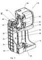
- Figures 1 to 3 show a holder according to the invention in a position of use (Figure 1), in an intermediate position ( Figure 2) and in a basic position ( Figure 3) and Figure 4 is a detail view according to arrow IV in Figure 2.
- Bracket has a frame 12 with a bottom 14 and a vertical, in the installed position the bracket 10 on the vertical side wall 16.
- the bracket 10 is for installation in an installation space of a center console, not shown, of a passenger car intended.
- the installation space has a prismatic shape of the frame 12 complementary shape with a rectangular base.
- top guide grooves 18 in which three springs 20 slidably are included.
- the springs 20 are in one piece with a slide 22.
- Guide grooves 18 and springs 20 form a sliding guide of the carriage 22 with which the carriage 22 is guided vertically displaceably on the frame 12.
- the shift of the Carriage 22 takes place with a known, not visible in the drawing Roll spring, i.e. a self-winding band spring, which is a slide spring element forms, which pulls the carriage 22 on the side wall 16 of the frame 12 upwards.
- the carriage 22 is against the force of the not visible carriage spring element down to the bottom 14 of the frame 12 can be pressed.
- the Carriage 22 held with a carriage lock, which in a manner known per se Heart curve locking (push-push mechanism) is formed.
- the slide lock has a triangular pin 24 in cross section at one end a pivot bolt 26 which is pivotally attached to the frame 12.
- the heart curve lock has a heart curve 28 with which the pin 24 engages and thereby locks the carriage 22 when the carriage 22 in its lower position is moved.
- the displacement of the carriage 22 is determined by a known, in the Drawing not visible damped rotary damper, the gear with a the side wall 16 combs vertically mounted rack 30.
- the holder 10 has a swivel device in the form of a swivel joint 32
- the pivot joint 32 comprises a pivot pin 34 made of metal, which is horizontal and attached perpendicular to the side wall 16 of the frame 12 on an edge of the carriage 22 is.
- a beverage container receptacle 36 is made by means of the swivel joint 32 a lateral basic position, as shown in Figures 2 and 3, in a horizontal, standing position of use, as shown in Figure 1, pivotable with the Carriage 22 connected.
- the beverage container receptacle 36 is approximately cuboid with approximately square base, with a corner of the square base is replaced by a quarter arc.
- the beverage container receptacle 36 has an adjustment opening 38 of circular cross-section for adjusting, for example Beverage can on.
- the beverage container receptacle 36 is in a manner known per se with a spring-operated compensation wing 40 pivoting into the adjustment opening 38 provided that after setting a beverage container in the setting opening 38 after is pressed outside.
- the compensating wing 40 presses a set in the setting opening 38 Beverage containers against an opposite side of the adjustment opening 38 and thereby causes a secure hold of beverage containers different Diameter in the beverage container receptacle 36.
- the beverage container receptacle 36 On its underside, the beverage container receptacle 36 has an integral, ribbed substructure 42 on which the swivel joint 32 is formed. Furthermore is the heart curve 28 of the carriage lock on one side of the base 42 of the Beverage container receptacle 36 attached.
- Figure 1 For swiveling the first beverage container holder 36 from its laterally lying basic position (FIG. 2) into its horizontal, standing use position ( Figure 1) is a swivel spring element in the form of a the drawing not visible leg spring provided, one leg on Carriage 22 and its other leg on the substructure 42 of the first beverage container receptacle 36 attacks.
- the pivoting movement of the first beverage container receptacle 36 is damped with a rotation damping element not visible in the drawing, whose gear meshes with an internal gear segment 46 which is fixed to the slide 22nd is appropriate.
- the internal gear segment 46 is coaxial with the pivot pin 34 of the Swivel joint 32 is arranged and extends over an arc that is longer than is a quarter circle and shorter than a semicircle.
- the holder 10 has a locking device which the first beverage container receptacle 36 in its lateral position against the Locked force of the pivot spring element not visible in the drawing when the Carriage 22 is not in its upper position.
- This shown in Figure 4 Locking device has a two-armed locking lever 60 which around a pivot pin 62 pivotable with the base 42 of the beverage container receptacle 36 is connected.
- the pivot pin 62 is parallel and at a distance at approximately the same height to the pivot pin of the pivot joint 32 of the beverage container receptacle 36.
- the locking lever 60 is a leg spring 64 in the direction of Arrow P pivots, in which it engages over a pin 66 when the beverage container receptacle 36 is in its lateral basic position.
- This position is in Figure 4 shown.
- the pin 66 is laterally projecting at a distance from the swivel joint 32 attached to the base 42 of the beverage container receptacle 36.
- the the Pin 66 of the beverage container receptacle 36 overlapping locking lever 60 locks the beverage container receptacle 36 in its laterally lying basic position against the force of the leg spring not visible in the drawing, which the Beverage container receptacle 36 in the direction of the horizontal use position presses.
- the beverage container receptacle 36 automatically unlocks when the carriage 22 reaches its upper end position.
- the attack 70 pivots the locking lever 60 through a small angle against the force of the Leg spring 64 against the direction of arrow P in Figure 4, so that the pin 66 on Underframe 42 of the beverage container receptacle 36 is released from the locking lever 60.
- the beverage container receptacle 36 is unlocked and is not visible from the Leg spring pivoted upwards into the horizontal position of use.
- the holder 10 has a second locking device which receives the first beverage container 36 locked in its horizontal standing position of use.
- the second locking device is on manually by pressing a button 48 on an upper side of the first beverage container receptacle 36 can be unlocked.
- first beverage container receptacle 36 In the first beverage container receptacle 36 is a second beverage container receptacle 50 with a substantially cylindrical shape is pivoted out laterally.
- the first is for swiveling out the second beverage container receptacle 50
- Beverage container receptacle 36 is provided with a recess 52 which extends over a Part of a circumference of the adjustment opening 38 of the first beverage container receptacle 36 extends.
- the second beverage container receptacle 50 has one point on its circumference one upward and one downward, not visible in the drawing Pivots on, which are in complementary holes on a corner of the first beverage container receptacle 36 intervene.
- the pivoting movement takes place in a manner known per se Way spring-actuated and is by means of a not visible in the drawing dampened known rotary damper.
- the second beverage container receptacle 50 locked by means of a locking device with a button 51 on the top the first beverage container receptacle 36 is detachable.
- the second beverage container receptacle 50 has a compensating flap 54 which can be pivoted about a horizontal axis on, the spring-actuated into the second beverage container receptacle 50 and thereby holding beverage containers of different diameters securely.
- the frame 12, the carriage 22, the two beverage container receptacles 36, 50 and further small parts of the holder 10 are made as injection molded parts made of plastic.
Landscapes
- Engineering & Computer Science (AREA)
- Transportation (AREA)
- Mechanical Engineering (AREA)
- Physics & Mathematics (AREA)
- Thermal Sciences (AREA)
- Passenger Equipment (AREA)
Abstract
Description
Claims (8)
- Halterung für einen Getränkebehälter in einem Kraftwagen, mit einer ersten Getränkebehälteraufnahme, die aus einer versenkten Grundstellung in eine Gebrauchsstellung bewegbar ist, dadurch gekennzeichnet, daß die Halterung (10) eine Schwenkeinrichtung (32) aufweist, mit der die Getränkebehälteraufnahme (36) verbunden und mit der die erste Getränkebehälteraufnahme (36) aus einer im wesentlichen seitlich liegenden Grundstellung in eine horizontal stehende Gebrauchsstellung schwenkbar ist.
- Halterung nach Anspruch 1, dadurch gekennzeichnet, daß die Halterung (10) eine Schiebeführung (18, 20) aufweist, mit der sie aus der versenkten Grundstellung nach oben verschiebbar geführt ist.
- Halterung nach Anspruch 2, dadurch gekennzeichnet, daß die Halterung (10) einen Schlitten (22) aufweist, der an der Schiebeführung (18, 20) von unten nach oben verschiebbar geführt ist und mit dem die Getränkebehälteraufnahme (36) über die Schwenkeinrichtung (32) schwenkbar verbunden ist.
- Halterung nach Anspruch 1, dadurch gekennzeichnet, daß die Halterung (10) ein Schwenkfederelement aufweist, das die Getränkebehälteraufnahme (36) an der Schwenkeinrichtung (32) aus der Grundstellung in die Gebrauchsstellung verschwenkt, und daß die Halterung (10) eine erste Verriegelungseinrichtung aufweist, die die Getränkebehälteraufnahme (36) gegen die Kraft des Schwenkfederelements in der Grundstellung hält.
- Halterung nach Anspruch 4, dadurch gekennzeichnet, daß die erste Verriegelungseinrichtung durch Erreichen einer oberen Endstellung des Schlittens (22) selbsttätig entriegelt wird.
- Halterung nach Anspruch 1, dadurch gekennzeichnet, daß die Halterung (10) eine zweite Verriegelungseinrichtung aufweist, die die erste Getränkebehälteraufnahme (36) in der horizontal stehenden Gebrauchsstellung fixiert.
- Halterung nach Anspruch 4, dadurch gekennzeichnet, daß die Halterung (10)ein Schlittenfederelement aufweist, das den Schlitten (22) von unten nach oben verschiebt, und daß die Halterung (10) eine Schlittenverriegelung (24, 26, 28) aufweist, die den Schlitten (22) gegen die Kraft des Schlittenfederelements in seiner unteren Stellung hält.
- Halterung nach Anspruch 1, dadurch gekennzeichnet, daß die Halterung (10) eine zweite Getränkebehälteraufnahme (50) aufweist, die herausbewegbar an der ersten Getränkebehälteraufnahme (36) angebracht ist.
Applications Claiming Priority (2)
| Application Number | Priority Date | Filing Date | Title |
|---|---|---|---|
| DE19821313 | 1998-05-13 | ||
| DE19821313A DE19821313C2 (de) | 1998-05-13 | 1998-05-13 | Halterung für einen Getränkebehälter in einem Kraftwagen |
Publications (2)
| Publication Number | Publication Date |
|---|---|
| EP0956995A2 true EP0956995A2 (de) | 1999-11-17 |
| EP0956995A3 EP0956995A3 (de) | 2001-01-17 |
Family
ID=7867562
Family Applications (1)
| Application Number | Title | Priority Date | Filing Date |
|---|---|---|---|
| EP99107001A Withdrawn EP0956995A3 (de) | 1998-05-13 | 1999-04-09 | Halterung für einen Getränkebehälter in einem Kraftwagen |
Country Status (5)
| Country | Link |
|---|---|
| US (1) | US6234438B1 (de) |
| EP (1) | EP0956995A3 (de) |
| JP (1) | JP3256194B2 (de) |
| KR (1) | KR19990087936A (de) |
| DE (1) | DE19821313C2 (de) |
Cited By (2)
| Publication number | Priority date | Publication date | Assignee | Title |
|---|---|---|---|---|
| EP1103416A3 (de) * | 1999-11-25 | 2003-08-06 | Fischerwerke Arthur Fischer GmbH & Co. KG | Halter für einen Getränkebehälter in einem Kraftwagen |
| WO2004035347A1 (de) * | 2002-10-11 | 2004-04-29 | Sego Gmbh | Becher- oder flaschenhalteranordnung insbesondere für ein kraftfahrzeug |
Families Citing this family (12)
| Publication number | Priority date | Publication date | Assignee | Title |
|---|---|---|---|---|
| DE10007594A1 (de) * | 2000-02-18 | 2001-08-23 | Fischer Artur Werke Gmbh | Halterung für einen Getränkebehälter |
| DE10016463A1 (de) * | 2000-04-01 | 2001-10-11 | Fischer Artur Werke Gmbh | Halter für einen Getränkebehälter |
| DE10250226B4 (de) * | 2002-10-11 | 2005-02-17 | Sego Gmbh | Becher- oder Flaschenhalteranordnung, insbesondere für ein Kraftfahrzeug |
| DE20216674U1 (de) * | 2002-10-29 | 2003-03-13 | TRW Automotive Electronics & Components GmbH & Co.KG, 67677 Enkenbach-Alsenborn | Getränkehalter |
| FR2850333B1 (fr) * | 2003-01-28 | 2005-03-04 | Peugeot Citroen Automobiles Sa | Support, notamment pour gobelet, prevu dans un vehicule automobile, et vehicule pourvu d'un tel support |
| US7121517B2 (en) * | 2004-08-20 | 2006-10-17 | General Motors Corporation | Cup holder assembly with sliding partial ring |
| US7367638B2 (en) * | 2005-05-31 | 2008-05-06 | Dell Products L.P. | Door panel system for an information handling system |
| DE102007051969A1 (de) * | 2007-10-31 | 2009-05-07 | Fischer Automotive Systems Gmbh & Co. Kg | Halter für einen Getränkebehälter |
| GB2543774B (en) * | 2015-10-27 | 2018-04-18 | Ford Global Tech Llc | Stowable table |
| US9958898B1 (en) | 2017-06-13 | 2018-05-01 | Dell Products, Lp | Compression assisted service access for narrow border mobile information handling systems |
| DE102018104788B4 (de) * | 2018-03-02 | 2024-02-08 | Dr. Schneider Kunststoffwerke Gmbh | Getränkehalter |
| TWI861858B (zh) * | 2022-07-14 | 2024-11-11 | 英屬開曼群島商睿能創意公司 | 置物架及使用其之載具 |
Citations (1)
| Publication number | Priority date | Publication date | Assignee | Title |
|---|---|---|---|---|
| DE4429515C1 (de) | 1994-08-19 | 1995-11-16 | Fischer Artur Werke Gmbh | Vorrichtung zum Halten von zwei Getränkebehältnissen in der Mittelkonsole eines Kraftfahrzeugs |
Family Cites Families (23)
| Publication number | Priority date | Publication date | Assignee | Title |
|---|---|---|---|---|
| US1967898A (en) * | 1933-02-08 | 1934-07-24 | Internat Machine & Tool Works | Ash tray and glass holder attachment for tables and other supports |
| US4759584A (en) * | 1985-04-18 | 1988-07-26 | Prince Corporation | Beverage container holder for vehicles |
| US4907775A (en) * | 1989-02-17 | 1990-03-13 | Chivas Products Limited | Container holder |
| US5014956A (en) * | 1989-03-02 | 1991-05-14 | Nk Innovations, Inc. | Adjustable drink holder |
| GB2241872A (en) * | 1990-03-15 | 1991-09-18 | Ford Motor Co | Retractable container holder |
| US5228611A (en) * | 1990-05-11 | 1993-07-20 | Toyoda Gosei Co., Ltd. | Container holder |
| US5171061A (en) * | 1990-09-17 | 1992-12-15 | Prince Corporation | Pull-out gear driven container holder |
| US5060899A (en) * | 1990-11-19 | 1991-10-29 | Chivas Products Limited | Nested container holders |
| US5131716A (en) * | 1991-05-14 | 1992-07-21 | Lear Seating Corporation | Vehicle cupholder with locking mechanism |
| US5297709A (en) * | 1992-04-03 | 1994-03-29 | Prince Corporation | Container holder |
| US5284314A (en) * | 1992-10-13 | 1994-02-08 | Davidson Textron Inc. | Modular dual mug and cup holder |
| US5330146A (en) * | 1993-12-07 | 1994-07-19 | Prince Corporation | Container holder |
| US5494249A (en) * | 1994-09-26 | 1996-02-27 | Chrysler Corporation | Container holder for vehicle wall panel |
| DE4444955A1 (de) * | 1994-12-16 | 1996-06-20 | Fischer Artur Werke Gmbh | Halter für Getränkebehälter |
| DE19507614A1 (de) * | 1995-03-04 | 1996-09-05 | Fischer Artur Werke Gmbh | Halterung für einen Getränkebehälter |
| US5673890A (en) * | 1995-04-20 | 1997-10-07 | Prince Corporation | Hinge mounting structure |
| US5690308A (en) * | 1995-06-07 | 1997-11-25 | Manchester Plastics, Inc. | Semi-automatic swing out cup holder |
| US5618018A (en) * | 1995-06-07 | 1997-04-08 | Manchester Plastics | Cup holder for confined spaces |
| DE19528488C1 (de) * | 1995-08-03 | 1997-04-24 | Fischer Artur Werke Gmbh | Halterung für zwei Getränkebehälter |
| US5762307A (en) * | 1996-05-23 | 1998-06-09 | Irvin Automotive Products | Retractable automotive cupholder for compact storage in an interior storage compartment |
| DE19630528A1 (de) * | 1996-07-29 | 1998-02-05 | Fischer Artur Werke Gmbh | Vorrichtung zum Halten zweier Getränkebehälter in der Mittelkonsole eines Kraftwagens |
| US5791617A (en) * | 1996-10-25 | 1998-08-11 | Boman; Larry Stuart | Stowable vehicle container holder |
| GB2326395A (en) * | 1997-06-21 | 1998-12-23 | Rover Group | A container holder for a motor vehicle |
-
1998
- 1998-05-13 DE DE19821313A patent/DE19821313C2/de not_active Expired - Fee Related
-
1999
- 1999-04-09 EP EP99107001A patent/EP0956995A3/de not_active Withdrawn
- 1999-04-16 KR KR1019990013448A patent/KR19990087936A/ko not_active Ceased
- 1999-05-07 US US09/307,038 patent/US6234438B1/en not_active Expired - Fee Related
- 1999-05-11 JP JP13021499A patent/JP3256194B2/ja not_active Expired - Fee Related
Patent Citations (1)
| Publication number | Priority date | Publication date | Assignee | Title |
|---|---|---|---|---|
| DE4429515C1 (de) | 1994-08-19 | 1995-11-16 | Fischer Artur Werke Gmbh | Vorrichtung zum Halten von zwei Getränkebehältnissen in der Mittelkonsole eines Kraftfahrzeugs |
Cited By (2)
| Publication number | Priority date | Publication date | Assignee | Title |
|---|---|---|---|---|
| EP1103416A3 (de) * | 1999-11-25 | 2003-08-06 | Fischerwerke Arthur Fischer GmbH & Co. KG | Halter für einen Getränkebehälter in einem Kraftwagen |
| WO2004035347A1 (de) * | 2002-10-11 | 2004-04-29 | Sego Gmbh | Becher- oder flaschenhalteranordnung insbesondere für ein kraftfahrzeug |
Also Published As
| Publication number | Publication date |
|---|---|
| EP0956995A3 (de) | 2001-01-17 |
| JP3256194B2 (ja) | 2002-02-12 |
| DE19821313A1 (de) | 1999-12-23 |
| JPH11334449A (ja) | 1999-12-07 |
| DE19821313C2 (de) | 2000-10-19 |
| KR19990087936A (ko) | 1999-12-27 |
| US6234438B1 (en) | 2001-05-22 |
Similar Documents
| Publication | Publication Date | Title |
|---|---|---|
| EP0730995B1 (de) | Halterung für einen Getränkebehälter | |
| EP1059198B1 (de) | Haltevorrichtung für einen Getränkebehälter | |
| AT508544B1 (de) | Kupplungsvorrichtung zum lösbaren verbinden einer schublade mit einer bewegbaren schiene | |
| EP0764558B1 (de) | Einbau-Vorrichtung insbesondere für Fahrzeuge | |
| EP0697308B1 (de) | Vorrichtung zum Halten von zwei Getränkebehältnissen in der Mittelkonsole eines Kraftfahrzeuges | |
| DE19528488C1 (de) | Halterung für zwei Getränkebehälter | |
| DE19821313C2 (de) | Halterung für einen Getränkebehälter in einem Kraftwagen | |
| EP3599129B1 (de) | Tischvorrichtung für ein kraftfahrzeug | |
| DE19616774C2 (de) | Trinkgefäßhalter für Fahrzeuge | |
| DE4444955A1 (de) | Halter für Getränkebehälter | |
| EP1386778A2 (de) | Drehbeweglicher Körper mit Entrastelement | |
| EP1176050A2 (de) | Haltevorrichtung für einen Getränkebehälter | |
| DE19531750A1 (de) | Kraftstofftankhalterung für Gabelstapler | |
| DE3602197A1 (de) | Ascher, insbesondere fuer kraftfahrzeuge | |
| EP1099596B1 (de) | Haltevorrichtung für einen Getränkebehälter | |
| DE20204882U1 (de) | Halter für einen Getränkebehälter | |
| EP0830974B1 (de) | Haltevorrichtung für einen Getränkebehälter | |
| DE19923414C1 (de) | Armstütze für ein mehrsitziges Fahrzeug | |
| EP1238854B1 (de) | Halterungsvorrichtung für Trinkgefässe in Kraftfahrzeugen | |
| EP1103416B1 (de) | Halter für einen Getränkebehälter in einem Kraftwagen | |
| EP1153790B1 (de) | Halter für ein Getränkegefäss | |
| EP0897832A1 (de) | Anordnung mit einer Gepäckraumabdeckung in einem Fahrzeug | |
| DE2948657C2 (de) | ||
| DE19630528A1 (de) | Vorrichtung zum Halten zweier Getränkebehälter in der Mittelkonsole eines Kraftwagens | |
| DE20111577U1 (de) | Halterungsvorrichtung für Behältnisse, insbesondere Getränkedosen, -flaschen oder Trinkgefäße, in Kraftfahrzeugen |
Legal Events
| Date | Code | Title | Description |
|---|---|---|---|
| PUAI | Public reference made under article 153(3) epc to a published international application that has entered the european phase |
Free format text: ORIGINAL CODE: 0009012 |
|
| AK | Designated contracting states |
Kind code of ref document: A2 Designated state(s): ES FR GB IT NL SE |
|
| AX | Request for extension of the european patent |
Free format text: AL;LT;LV;MK;RO;SI |
|
| PUAL | Search report despatched |
Free format text: ORIGINAL CODE: 0009013 |
|
| AK | Designated contracting states |
Kind code of ref document: A3 Designated state(s): AT BE CH CY DE DK ES FI FR GB GR IE IT LI LU MC NL PT SE |
|
| AX | Request for extension of the european patent |
Free format text: AL;LT;LV;MK;RO;SI |
|
| 17P | Request for examination filed |
Effective date: 20010518 |
|
| AKX | Designation fees paid |
Free format text: ES FR GB IT NL SE |
|
| REG | Reference to a national code |
Ref country code: DE Ref legal event code: 8566 |
|
| 17Q | First examination report despatched |
Effective date: 20050523 |
|
| STAA | Information on the status of an ep patent application or granted ep patent |
Free format text: STATUS: THE APPLICATION IS DEEMED TO BE WITHDRAWN |
|
| 18D | Application deemed to be withdrawn |
Effective date: 20051101 |