EP0957035A1 - Bec verseur ayant des moyens de dosage - Google Patents
Bec verseur ayant des moyens de dosage Download PDFInfo
- Publication number
- EP0957035A1 EP0957035A1 EP98201577A EP98201577A EP0957035A1 EP 0957035 A1 EP0957035 A1 EP 0957035A1 EP 98201577 A EP98201577 A EP 98201577A EP 98201577 A EP98201577 A EP 98201577A EP 0957035 A1 EP0957035 A1 EP 0957035A1
- Authority
- EP
- European Patent Office
- Prior art keywords
- cap
- dispensing
- internal
- dispensing spout
- skirt
- Prior art date
- Legal status (The legal status is an assumption and is not a legal conclusion. Google has not performed a legal analysis and makes no representation as to the accuracy of the status listed.)
- Withdrawn
Links
Images


Classifications
-
- B—PERFORMING OPERATIONS; TRANSPORTING
- B65—CONVEYING; PACKING; STORING; HANDLING THIN OR FILAMENTARY MATERIAL
- B65D—CONTAINERS FOR STORAGE OR TRANSPORT OF ARTICLES OR MATERIALS, e.g. BAGS, BARRELS, BOTTLES, BOXES, CANS, CARTONS, CRATES, DRUMS, JARS, TANKS, HOPPERS, FORWARDING CONTAINERS; ACCESSORIES, CLOSURES, OR FITTINGS THEREFOR; PACKAGING ELEMENTS; PACKAGES
- B65D47/00—Closures with filling and discharging, or with discharging, devices
- B65D47/04—Closures with discharging devices other than pumps
- B65D47/06—Closures with discharging devices other than pumps with pouring spouts or tubes; with discharge nozzles or passages
- B65D47/065—Closures with discharging devices other than pumps with pouring spouts or tubes; with discharge nozzles or passages with hinged, foldable or pivotable spouts
- B65D47/066—Closures with discharging devices other than pumps with pouring spouts or tubes; with discharge nozzles or passages with hinged, foldable or pivotable spouts the spout being either flexible or having a flexible wall portion, whereby the spout is foldable between a dispensing and a non-dispensing position
Definitions
- the present invention relates to a one-piece dispensing cap comprising a dosing means.
- Dispensing caps for closing plastic bottles of laundry or cleaning products are representative of the various dispensing caps for closing containers, to which the present invention can apply; such dispensing caps typically comprise, for example, a cap solid base, cap external walls that further comprise a means, for example a thread, that allows to fix the cap onto the bottle's neck. Such caps typically further comprise a dispensing nozzle which is pivotally attached to the solid base, for example by the means of a hinge.
- the base comprises an external wall with a means (a thread) for screwing the cap onto a container's neck.
- the dispensing passage is hingeably connected to the base so that the cap can be open and closed.
- the cap further comprises an internal wall that partially fits into the bottles neck so as to provide a seal means.
- the one piece dispensing caps as described in the preceding documents are known and used for the closing of bottles of various consumer goods.
- a one piece dispensing cap that also features a dosing means, so that the user can either dispense the product via the dispensing spout, or use the dosing means to dispense a given volume of product.
- the present invention is directed to a one-piece cap comprising a closure base, a dispensing spout defining a passage through the closure base, to which it is hingeably attached by a flexible diaphragm, and internal and external closure walls, characterized in that the internal wall extends so as to form a dosing volume.
- the cap is further designed to fit onto the neck of the bottle so that the assembly is leak-proof, and further designed so that the dispensing nozzle is leak-proof when in the closed position.
- a cap (1) comprising a rigid base (10), a rigid dispensing spout (11), a rectilinear pivot line (12) in a bi-sector plane (29) hereinafter described, a dispensing passage (13), and a flexible invertible diaphragm (14).
- the rigid base (10) comprises an external wall and an internal wall that define respectively an external skirt (15) and internal skirt (16).
- Said external skirt (15) further comprises an attaching means (17) for securing the cap (1) onto an associated container (18), preferably onto the neck of said associated container (18).
- Said attaching means (17) can be a bayonet system made out of at least two ribs and/or grooves located on the cap that fit into corresponding ribs and/or grooves located on the neck of the bottle, but preferably, said attaching means (17) comprises at least one thread for screwing the cap (1) onto a corresponding at least one thread located on the neck of a container such as a plastic bottle (see figure 2).
- the container (18) is intended for containing liquids or powders, preferably liquids, and most preferably liquids for household cleaning or laundry purposes.
- Such liquids can be poured directly onto the surface to clean, in the case they are to be used locally without dilution, or they can also be diluted, for example in water, preferably in the case of use onto large surfaces to clean, or into devices such as washing-machines for example.
- the user needs a dosing volume of reference so as to dose a given volume of contents to be diluted relatively to a given volume of water.
- a dosing means is preferably achieved as shown in figure 2: the internal skirt (16) extends from the rigid base (10), so as to form a substantially cylindrical volume.
- the base of the rigid dispensing spout (11) is attached to the invertible diaphragm (14) by integrally formed hinges (21). All other portions of the invertible diaphragm (14) are resilient to enable said invertible diaphragm (14) to invert.
- the invertible diaphragm (14) is proximate to a bi-sector plane (29) which bisects the angle between an inside surface of the rigid dispensing spout (11), and a rigid base seal surface (20), when the dispensing spout (11) is in the dispensing position (see figure 2) and the invertible diaphragm (14) is in a convex configuration.
- the rectilinear pivot line (12) lies in the bi-sector plane (29).
- the invertible diaphragm (14) is connected with the rigid base (10) by the hinge connection (21).
- the hinge (21) and the pivot line (12) lie in the bi-sector plane (29), and in effect form a continuous hinge.
- the invertible diaphragm (14) is connected with the rigid dispensing spout (11) by the relatively thin hinge (19).
- Said hinge (19) has sufficient width and flexibility to allow the invertible diaphragm (14) to invert without significantly impeding its movement.
- the invertible diaphragm (14) inverts about the bi-sector plane (29) in the manner shown in figures 5a, 5b, 5c, throughout the extent thereof to a concaved configuration.
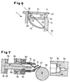
- a cup seal (22) on the inside surface of rigid dispensing spout (11) is thus urged to engage the rigid base seal surface (20) to complete the sealing, as shown in figure 6.
- the invertible diaphragm (14) is in its convexed configuration (see figures 2, 10) or its concaved configuration (see figures 11, 12), it is stable and substantially unstressed, only being stressed when it is flexed through the bi-sector plane (29). Dynamic forces, developed during this flexing through the bi-sector plane (29), exert pressure in the closed position to urge the dispensing spout cup seal (22) against the rigid base seal surface (20). Force is required to open the rigid dispensing spout (11), by lifting it past the bi-sector plane (29), whereupon the dynamic forces built up in the invertible diaphragm urge the dispensing spout (11) toward its dispensing position shown in figure 2.
- both ends of the spout abut against the rigid base (10) when closing, as shown in figure 6.
- the cup seal (22) on the inside surface of the rigid dispensing spout (11) compresses and deforms when the dispensing end of the rigid dispensing spout (11) engages the rigid base latch surface (23), the seal acting in the manner of a Belleville spring, thereby providing a firm seating against the rigid base seal surface (20) and positive sealing.
- Figures 2, 6 show a preferred embodiment of the present invention wherein the cap comprises a rigid base latch surface (23) and an inclined portion (24) for securing the dispensing spout (11) in the sealed position.
- the dispensing spout (11) has an inclined surface (25) which serves as a lead-in upon contact with the rigid base latch surface (23) during closing.
- Figures 5a, 5b, 5c show a form of the closure of the invention wherein the invertible diaphragm (14), comprising facets (26a), (26b), (26c), (26d), and (26e), has a dispensing spout (11) of rectangular cross-section.
- the rigid dispensing spout (11) is connected to facets (26b), (26c) and (26d) by the pivot line (12) and to the rigid base (10) by hinge connections. These facets cooperate to define the invertible diaphragm.
- FIG. 5b shows the invertible facets (26a.b.c.d.e) of the invertible diaphragm (14) collapsing collectively through the bi-sector plane (29).
- an embodiment of the present invention as before described, comprises an invertible diaphragm (14) which is multi-faced (figures 5a.b.c), other shapes for the invertible diaphragm (14) can be applied to the present invention, for example said invertible diaphragm (14) can be conic-shaped, or dome-shaped, all of which diaphragms operating in the manner hereinbefore described to invert from a convexed to a concaved configuration.
- the invertible diaphragm can be in the form of a hollowed conic section. When it is in concaved configuration and the dispensing spout is in sealing position, the geometry is not a mirror image, but has increased surface area on the inside surface. Therefore, when pressure is exerted upon it by the fluid contents within a container, the invertible diaphragm distributes this pressure along the bi-sector plane which increases sealing pressure on the cup seal.
- This type of seal when abutting the rigid base seal surface (20), is compressed and acts as a Belleville spring to hold the dispensing end of the dispensing spout (11) to the rigid base latch surface (23).
- figures 1 to 6 show the rigid dispensing spout (11) with a projection (27) to facilitate easy manual movement from the sealing position.
- the cap (1) is adapted to be molded in the dispensing position and moved to the sealed position during the molding cycle.
- the molding cycle consists of the mold closing with surface (63) of cavity (60) contacting a stripper plate having a surface (62) and an ejector half surface (64) which contacts an ejector surface (65).
- plastic is injected into the cavity (59) to form a molded closure.
- the surfaces (62) and (63) separate.
- plates (54) and (55) move back to separate surfaces (64) and (65) and retract a core (66).
- a mold wipe (58) traverses the surface of the mold in the direction indicated by the arrow on wipe (58), and contacts the rigid dispensing spout to move the dispensing spout (11) to the sealed position.
- the stripper plate (57) moves forward and ejects the molded part from the mold and off of the core (56). This eliminates the necessity for any secondary operation to close the rigid dispensing spout (11), and has the additional advantage that the mechanical flexing of the tinged connection at the bi-sector plane (29) and hinge (19) during the molding cycle, orients the molecules of the preferred polyolefin material to insure long hinge life.
Landscapes
- Engineering & Computer Science (AREA)
- Mechanical Engineering (AREA)
- Closures For Containers (AREA)
Priority Applications (3)
| Application Number | Priority Date | Filing Date | Title |
|---|---|---|---|
| EP98201577A EP0957035A1 (fr) | 1998-05-12 | 1998-05-12 | Bec verseur ayant des moyens de dosage |
| AU38854/99A AU3885499A (en) | 1998-05-12 | 1999-05-07 | Pour spout having dosing means |
| PCT/US1999/009912 WO1999058413A1 (fr) | 1998-05-12 | 1999-05-07 | Bec verseur avec mecanisme doseur |
Applications Claiming Priority (1)
| Application Number | Priority Date | Filing Date | Title |
|---|---|---|---|
| EP98201577A EP0957035A1 (fr) | 1998-05-12 | 1998-05-12 | Bec verseur ayant des moyens de dosage |
Publications (1)
| Publication Number | Publication Date |
|---|---|
| EP0957035A1 true EP0957035A1 (fr) | 1999-11-17 |
Family
ID=8233720
Family Applications (1)
| Application Number | Title | Priority Date | Filing Date |
|---|---|---|---|
| EP98201577A Withdrawn EP0957035A1 (fr) | 1998-05-12 | 1998-05-12 | Bec verseur ayant des moyens de dosage |
Country Status (3)
| Country | Link |
|---|---|
| EP (1) | EP0957035A1 (fr) |
| AU (1) | AU3885499A (fr) |
| WO (1) | WO1999058413A1 (fr) |
Cited By (2)
| Publication number | Priority date | Publication date | Assignee | Title |
|---|---|---|---|---|
| EP1125854A1 (fr) * | 2000-02-17 | 2001-08-22 | Crown Cork & Seal Technologies Corporation | Amélioration d'une fermeture de distribution |
| NL2003180C2 (nl) * | 2008-01-18 | 2010-05-19 | Weasy Pack Internat Ltd | Schenkverpakking en schenkorgaan. |
Families Citing this family (1)
| Publication number | Priority date | Publication date | Assignee | Title |
|---|---|---|---|---|
| TWI289530B (en) * | 2002-05-16 | 2007-11-11 | Sig Technology Ltd | Pouring closure for liquid packagings |
Citations (6)
| Publication number | Priority date | Publication date | Assignee | Title |
|---|---|---|---|---|
| CH321464A (de) * | 1955-10-31 | 1957-05-15 | Gimelli & Co | Verschlussvorrichtung an einer mit einem Hals versehenen Flasche |
| CH605308A5 (en) * | 1976-06-10 | 1978-09-29 | Migros | Bottle seal with pouring device |
| FR2646653A1 (fr) * | 1989-05-03 | 1990-11-09 | Taupin Jean Paul | Bec doseur-verseur pour recipient de conditionnement de produits liquides, pulverulents ou granuleux |
| WO1994001339A1 (fr) * | 1992-07-03 | 1994-01-20 | Henkel Kommanditgesellschaft Auf Aktien | Fermeture d'un recipient contenant un produit pulverulent ou coulant |
| WO1994029182A1 (fr) * | 1993-06-14 | 1994-12-22 | Dark Richard C G | Dispositif de fermeture ameliore |
| WO1997031836A1 (fr) * | 1996-02-27 | 1997-09-04 | Budev B.V. | Dispositif de fermeture a entonnoir retractable |
Family Cites Families (1)
| Publication number | Priority date | Publication date | Assignee | Title |
|---|---|---|---|---|
| US4440327A (en) | 1981-01-26 | 1984-04-03 | Dark Richard C G | Fluid dispensing closure with integral valve |
-
1998
- 1998-05-12 EP EP98201577A patent/EP0957035A1/fr not_active Withdrawn
-
1999
- 1999-05-07 AU AU38854/99A patent/AU3885499A/en not_active Abandoned
- 1999-05-07 WO PCT/US1999/009912 patent/WO1999058413A1/fr not_active Ceased
Patent Citations (6)
| Publication number | Priority date | Publication date | Assignee | Title |
|---|---|---|---|---|
| CH321464A (de) * | 1955-10-31 | 1957-05-15 | Gimelli & Co | Verschlussvorrichtung an einer mit einem Hals versehenen Flasche |
| CH605308A5 (en) * | 1976-06-10 | 1978-09-29 | Migros | Bottle seal with pouring device |
| FR2646653A1 (fr) * | 1989-05-03 | 1990-11-09 | Taupin Jean Paul | Bec doseur-verseur pour recipient de conditionnement de produits liquides, pulverulents ou granuleux |
| WO1994001339A1 (fr) * | 1992-07-03 | 1994-01-20 | Henkel Kommanditgesellschaft Auf Aktien | Fermeture d'un recipient contenant un produit pulverulent ou coulant |
| WO1994029182A1 (fr) * | 1993-06-14 | 1994-12-22 | Dark Richard C G | Dispositif de fermeture ameliore |
| WO1997031836A1 (fr) * | 1996-02-27 | 1997-09-04 | Budev B.V. | Dispositif de fermeture a entonnoir retractable |
Cited By (2)
| Publication number | Priority date | Publication date | Assignee | Title |
|---|---|---|---|---|
| EP1125854A1 (fr) * | 2000-02-17 | 2001-08-22 | Crown Cork & Seal Technologies Corporation | Amélioration d'une fermeture de distribution |
| NL2003180C2 (nl) * | 2008-01-18 | 2010-05-19 | Weasy Pack Internat Ltd | Schenkverpakking en schenkorgaan. |
Also Published As
| Publication number | Publication date |
|---|---|
| AU3885499A (en) | 1999-11-29 |
| WO1999058413A1 (fr) | 1999-11-18 |
Similar Documents
| Publication | Publication Date | Title |
|---|---|---|
| US4440327A (en) | Fluid dispensing closure with integral valve | |
| EP1291288B1 (fr) | Tube pourvu d'une soupape | |
| US6510971B1 (en) | Liquid dispensing closure | |
| CA2464052C (fr) | Dispositif de fermeture dote d'une valve actionnee par la pression et d'un joint de couvercle | |
| US5950848A (en) | Cap articulated to a connecting element | |
| EP1371579B1 (fr) | Mécanisme de vanne pour conteneur de liquide | |
| CN101238043B (zh) | 关闭件 | |
| US3516581A (en) | Toggle type closure | |
| CA2387776C (fr) | Structure de distribution a enfoncer a valve ouvrable sous l'effet de la pression | |
| US11040805B2 (en) | Closure for a container | |
| JP6027438B2 (ja) | 関節式後方フランジを備えるトグル式分注用クロージャ | |
| US10518945B2 (en) | Closure for a container | |
| WO2002040365A1 (fr) | Charniere en elastomere pour un couvercle de fermeture | |
| GB2098184A (en) | Dispensing closure for fluent material | |
| US4505400A (en) | Slide type cap closure | |
| EP0957035A1 (fr) | Bec verseur ayant des moyens de dosage | |
| EP1954584A1 (fr) | Capsules de distribution pour contenants a liquides | |
| US6143229A (en) | Method for making a dispensing closure with a finger well formed after molding of the dispensing closure | |
| JP7370665B2 (ja) | 注出器 | |
| KR20070047941A (ko) | 디스펜싱 밸브 클로우져 | |
| WO2006000739A1 (fr) | Bouchon de distribution pour recipients de liquide | |
| JPH11240529A (ja) | スクイズ性を有する合成樹脂製容器 | |
| AU2002234181B9 (en) | Elastomeric hinge for a closure lid | |
| AU2002234181A1 (en) | Elastomeric hinge for a closure lid |
Legal Events
| Date | Code | Title | Description |
|---|---|---|---|
| PUAI | Public reference made under article 153(3) epc to a published international application that has entered the european phase |
Free format text: ORIGINAL CODE: 0009012 |
|
| AK | Designated contracting states |
Kind code of ref document: A1 Designated state(s): AT BE CH DE DK ES FI FR GB GR IE IT LI LU NL PT SE |
|
| AX | Request for extension of the european patent |
Free format text: AL;LT;LV;MK;RO;SI |
|
| 17P | Request for examination filed |
Effective date: 20000308 |
|
| AKX | Designation fees paid |
Free format text: AT BE CH CY DE DK ES FI FR GB GR IE IT LI LU NL PT |
|
| RBV | Designated contracting states (corrected) |
Designated state(s): AT BE CH DE DK ES FI FR GB GR IE IT LI LU NL PT SE |
|
| STAA | Information on the status of an ep patent application or granted ep patent |
Free format text: STATUS: THE APPLICATION IS DEEMED TO BE WITHDRAWN |
|
| 18D | Application deemed to be withdrawn |
Effective date: 20011201 |