EP0957230A1 - Vorrichtung zum Sichern des Tuchs einer Abschirmvorrichtung - Google Patents
Vorrichtung zum Sichern des Tuchs einer Abschirmvorrichtung Download PDFInfo
- Publication number
- EP0957230A1 EP0957230A1 EP99201256A EP99201256A EP0957230A1 EP 0957230 A1 EP0957230 A1 EP 0957230A1 EP 99201256 A EP99201256 A EP 99201256A EP 99201256 A EP99201256 A EP 99201256A EP 0957230 A1 EP0957230 A1 EP 0957230A1
- Authority
- EP
- European Patent Office
- Prior art keywords
- cloth
- roll
- cloth roll
- latching elements
- latching
- Prior art date
- Legal status (The legal status is an assumption and is not a legal conclusion. Google has not performed a legal analysis and makes no representation as to the accuracy of the status listed.)
- Withdrawn
Links
- 239000004744 fabric Substances 0.000 title claims abstract description 152
- 238000000034 method Methods 0.000 title claims abstract description 5
- 238000010276 construction Methods 0.000 claims description 7
- 239000000203 mixture Substances 0.000 claims description 2
- 238000004804 winding Methods 0.000 description 2
- 238000007792 addition Methods 0.000 description 1
- 238000013459 approach Methods 0.000 description 1
- 238000004891 communication Methods 0.000 description 1
- 239000000463 material Substances 0.000 description 1
- 230000013011 mating Effects 0.000 description 1
- 238000012986 modification Methods 0.000 description 1
- 230000004048 modification Effects 0.000 description 1
Images


Classifications
-
- E—FIXED CONSTRUCTIONS
- E04—BUILDING
- E04F—FINISHING WORK ON BUILDINGS, e.g. STAIRS, FLOORS
- E04F10/00—Sunshades, e.g. Florentine blinds or jalousies; Outside screens; Awnings or baldachins
- E04F10/02—Sunshades, e.g. Florentine blinds or jalousies; Outside screens; Awnings or baldachins of flexible canopy materials, e.g. canvas ; Baldachins
- E04F10/06—Sunshades, e.g. Florentine blinds or jalousies; Outside screens; Awnings or baldachins of flexible canopy materials, e.g. canvas ; Baldachins comprising a roller-blind with means for holding the end away from a building
- E04F10/0644—Sunshades, e.g. Florentine blinds or jalousies; Outside screens; Awnings or baldachins of flexible canopy materials, e.g. canvas ; Baldachins comprising a roller-blind with means for holding the end away from a building with mechanisms for unrolling or balancing the blind
- E04F10/0655—Sunshades, e.g. Florentine blinds or jalousies; Outside screens; Awnings or baldachins of flexible canopy materials, e.g. canvas ; Baldachins comprising a roller-blind with means for holding the end away from a building with mechanisms for unrolling or balancing the blind acting on the movable end, e.g. front bar
-
- E—FIXED CONSTRUCTIONS
- E04—BUILDING
- E04F—FINISHING WORK ON BUILDINGS, e.g. STAIRS, FLOORS
- E04F10/00—Sunshades, e.g. Florentine blinds or jalousies; Outside screens; Awnings or baldachins
- E04F10/02—Sunshades, e.g. Florentine blinds or jalousies; Outside screens; Awnings or baldachins of flexible canopy materials, e.g. canvas ; Baldachins
- E04F10/06—Sunshades, e.g. Florentine blinds or jalousies; Outside screens; Awnings or baldachins of flexible canopy materials, e.g. canvas ; Baldachins comprising a roller-blind with means for holding the end away from a building
- E04F10/0607—Sunshades, e.g. Florentine blinds or jalousies; Outside screens; Awnings or baldachins of flexible canopy materials, e.g. canvas ; Baldachins comprising a roller-blind with means for holding the end away from a building with guiding-sections for supporting the movable end of the blind
-
- E—FIXED CONSTRUCTIONS
- E06—DOORS, WINDOWS, SHUTTERS, OR ROLLER BLINDS IN GENERAL; LADDERS
- E06B—FIXED OR MOVABLE CLOSURES FOR OPENINGS IN BUILDINGS, VEHICLES, FENCES OR LIKE ENCLOSURES IN GENERAL, e.g. DOORS, WINDOWS, BLINDS, GATES
- E06B9/00—Screening or protective devices for wall or similar openings, with or without operating or securing mechanisms; Closures of similar construction
- E06B9/56—Operating, guiding or securing devices or arrangements for roll-type closures; Spring drums; Tape drums; Counterweighting arrangements therefor
- E06B9/58—Guiding devices
-
- E—FIXED CONSTRUCTIONS
- E06—DOORS, WINDOWS, SHUTTERS, OR ROLLER BLINDS IN GENERAL; LADDERS
- E06B—FIXED OR MOVABLE CLOSURES FOR OPENINGS IN BUILDINGS, VEHICLES, FENCES OR LIKE ENCLOSURES IN GENERAL, e.g. DOORS, WINDOWS, BLINDS, GATES
- E06B9/00—Screening or protective devices for wall or similar openings, with or without operating or securing mechanisms; Closures of similar construction
- E06B9/56—Operating, guiding or securing devices or arrangements for roll-type closures; Spring drums; Tape drums; Counterweighting arrangements therefor
- E06B9/78—Operating, guiding or securing devices or arrangements for roll-type closures; Spring drums; Tape drums; Counterweighting arrangements therefor for direct manual operation, e.g. by tassels, by handles
Definitions
- the invention relates to a method for securing a cloth of a screen device which has been unwound from a cloth roll, wherein a cloth beam, whose ends are guided along fixedly disposed guide members, is fixed to the free end of the cloth remote from the end of the cloth which is fixed to the cloth roll in a connecting point, and wherein the cloth is unwound from the cloth roll by rotating said cloth roll in one direction.
- the cloth is generally unwound in a direction parallel to a window or the like which is to be screened, in order to function as a sun blind.
- movements of the screen caused by wind and the like cause disturbance, for example when working with computer terminals and the like.
- this objective can be accomplished in that, once the cloth has been completely unwound from the cloth roll by rotating the cloth roll in one direction, the cloth roll is rotated further in the same direction, thereby pulling the cloth beam towards the cloth roll again in order to bring latching elements connected to the cloth beam in engagement with further latching elements connected to said guide members, and the cloth roll is rotated in the opposite direction again in order to release the latching engagement between said latching elements.
- Another aspect of the invention relates to a screen device comprising a cloth roll and a cloth, which is connected to said cloth roll with one end in a connecting point, whilst a cloth beam is fixed to the free end of the cloth remote from the cloth roll, which cloth beam extends between two fixedly disposed guide members for guiding the ends of the cloth beam.
- first latching elements are provided on the ends of the cloth beam, which elements mate with second latching elements connected to said guide members, along which the latching elements connected to said cloth beam move when the cloth beam is unwound from the cloth roll by rotation of the cloth roll in a first direction of rotation, the construction being such that when the first latching elements, after having passed the second latching elements in a first direction, are moved in opposite direction by continued rotation of the cloth roll in the first direction of rotation, the first and the second latching elements will engage each other so as to secure the cloth beam with respect to the guide members, and that the latching engagement of latching elements will be released upon subsequent rotation of the cloth roll in a direction of rotation opposed to the first direction of rotation.
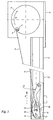
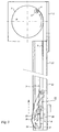
- the screen device which is schematically shown in the figures comprises a cloth roll 1, which is mounted in a frame 2 to be fixed to a wall of a building or the like, in such a manner that it is capable of rotation about a (usually horizontal) axis of rotation.
- a cloth beam 6 is fixed to the end of cloth 3 remote from the cloth roll.
- Closing plates 7 are fixed to the ends of cloth beam 6 by means of pins 7' ( Figures 4, 5) which are integrally formed with said closing plates 7 and which extend into recesses in cloth beam 6.
- a hub 8, which is in one piece with closing plate 7 is fixed to the side of closing plate 7 remote from the cloth beam.
- a flange 9, which extends parallel to the closing plate 7 and which is integrally formed with hub 8, is provided on the free end of hub 8.
- a pin 10 is inserted in a bore which extends through flange 9 and hub 8, in such a manner that pin 10 projects from flange 9 along part of its length.
- Guide members in the form of sections 11 of substantially C-shaped cross-section are provided for guiding the cloth beam 6 during the winding and unwinding of cloth 3 on and from cloth roll 1.
- the construction is thereby such that the hubs 8 mounted on the ends of cloth beam 6 can move through the gap which is bounded by the facing ends of said C-shaped sections, whilst flanges 9 are positioned in the interior of the guide members or sections 11.
- each section 11 Provided near the lower end of each section 11 is a latching element made up of an elongated member 12, which is connected to section 11 near its upper end by means of a screw 13 and a nut 14, in such a manner that latching element 12 is capable of pivoting movement with respect to section 11 about a pivot pin in the form of screw 13 extending parallel to the cloth roll.
- Latching element 12 is provided with a groove 15 which is open on its upper end, which groove, in the position wherein latching element 12 is freely suspended in section 11 in unloaded condition, extends approximately parallel to the longitudinal axis of said section and in the path of movement of a pin 10 which moves downwards in the direction indicated by arrow A ( Figure 1) in said section when cloth 3 is being unwound.
- Said groove 15 blends near its lower end into a groove 16 which slopes downwards at an obtuse angle with respect to groove 15.
- Latching element 12 is furthermore provided with a more or less V-shaped recess 17 beside groove 16, which recess is present at substantially the same height as groove 16, whereby groove 16 and recess 17 are in open communication with each other near their upper ends.
- a groove 18 sloping upwards in the direction of groove 15 connects to the upper end of recess 17, which groove 18 opens into the upper end of groove 15 near its upper end.
- a recess 20 is provided in the underside of the portion 19 of the latching element that is present between grooves 15 and 18, which recess is bounded by boundary surfaces whose free ends 21 and 22 are disposed on either side of the end facing towards said recess 20 of the portion 23 of latching element 12 that is disposed between groove 16 and recess 17.
- the cloth beam 6 will move downwards along sections 11 in the direction indicated by arrow A upon unwinding of cloth 3, in that the cloth roll is rotated in the direction indicated by arrow D.
- the pins 10 on cloth roll 6, which form latching elements will move downwards in grooves 15.
- the construction is thereby such that when the connecting point of cloth 3 on cloth roll 1, that is, rope 4, reaches its lowermost position, seen in Figure 1, once the cloth has been completely unwound from the cloth roll, pins 10 will have passed the lower ends 22 of the boundary surfaces of recess 20 and have moved to a position under recess 20 as a result of their movement in grooves 16.
- the cloth roll When the cloth is to be wound up, the cloth roll will be rotated in a direction opposed to the direction indicated by arrow D ( Figure 3).
- the cloth beam 6 and the pins 10 fixed thereto will initially move downwards thereby, with pins 10 moving into recesses 17 due to the above-described form of the recesses 20 and of the parts 23 of latching elements 12 that are disposed between grooves 16 and recesses 17.
- pins 10 When the rotation of the cloth roll is continued in a direction opposed to the direction indicated by arrow D, pins 10 will move upwards through groove 18 in the direction indicated by arrow B, as a result of which they will be released from latching elements 12 when cloth 3 is being wound up.
- Said rotation of the cloth roll can be effected by hand in the usual manner, of course.
- an electric motor accommodated within the cloth roll is used, which motor and the associated parts are so constructed that the motor will turn off automatically when a certain resistance is encountered during rotation of the cloth roll in the direction indicated by arrow D, because the cloth beam 6 is being locked against movement in the direction indicated by arrow B in the above-described manner.
- the latching element 27 which is shown in Figure 9 can be used, which latching element can be fixedly disposed in a respective section 11.
- Said latching element 27 is thereby provided with a groove 15' similar to groove 15, which opens at its upper end into a funnel-shaped recess 28, which is open at its upper end.
- Said latching element 27 is furthermore provided with parts 16' - 23' corresponding to the above-described parts 16 - 23.
- latching elements "connected" to guide members 11 may for example be disposed at some distance from said guide members.
Landscapes
- Engineering & Computer Science (AREA)
- Architecture (AREA)
- Structural Engineering (AREA)
- Civil Engineering (AREA)
- Operating, Guiding And Securing Of Roll- Type Closing Members (AREA)
Applications Claiming Priority (2)
| Application Number | Priority Date | Filing Date | Title |
|---|---|---|---|
| NL1009133A NL1009133C2 (nl) | 1998-05-12 | 1998-05-12 | Werkwijze voor het vastzetten van het doek van een scherminrichting. |
| NL1009133 | 1998-05-12 |
Publications (1)
| Publication Number | Publication Date |
|---|---|
| EP0957230A1 true EP0957230A1 (de) | 1999-11-17 |
Family
ID=19767117
Family Applications (1)
| Application Number | Title | Priority Date | Filing Date |
|---|---|---|---|
| EP99201256A Withdrawn EP0957230A1 (de) | 1998-05-12 | 1999-04-20 | Vorrichtung zum Sichern des Tuchs einer Abschirmvorrichtung |
Country Status (2)
| Country | Link |
|---|---|
| EP (1) | EP0957230A1 (de) |
| NL (1) | NL1009133C2 (de) |
Cited By (4)
| Publication number | Priority date | Publication date | Assignee | Title |
|---|---|---|---|---|
| NL1017112C2 (nl) * | 2001-01-15 | 2002-07-16 | Jakob Lassche | Blokkeerinrichting. |
| EP1127996A3 (de) * | 2000-02-24 | 2003-09-24 | Kurt Raffl | Struktur und automatischer Sperrmechanismus für Markisen |
| EP1598515A1 (de) * | 2004-05-14 | 2005-11-23 | Cardo Door Ab | Verfahren zum Betrieb eines Rolltores |
| ITRM20110661A1 (it) * | 2011-12-12 | 2013-06-13 | Va Ila S P A | Dispositivo di aggancio e bloccaggio a fine corsa preferibilmente per tende avvolgibili |
Citations (1)
| Publication number | Priority date | Publication date | Assignee | Title |
|---|---|---|---|---|
| US4509576A (en) * | 1982-11-09 | 1985-04-09 | Serafini Giovanni | Sunshade fitting convertible into veranda curtain fitting |
-
1998
- 1998-05-12 NL NL1009133A patent/NL1009133C2/nl not_active IP Right Cessation
-
1999
- 1999-04-20 EP EP99201256A patent/EP0957230A1/de not_active Withdrawn
Patent Citations (1)
| Publication number | Priority date | Publication date | Assignee | Title |
|---|---|---|---|---|
| US4509576A (en) * | 1982-11-09 | 1985-04-09 | Serafini Giovanni | Sunshade fitting convertible into veranda curtain fitting |
Cited By (6)
| Publication number | Priority date | Publication date | Assignee | Title |
|---|---|---|---|---|
| EP1127996A3 (de) * | 2000-02-24 | 2003-09-24 | Kurt Raffl | Struktur und automatischer Sperrmechanismus für Markisen |
| NL1017112C2 (nl) * | 2001-01-15 | 2002-07-16 | Jakob Lassche | Blokkeerinrichting. |
| EP1223262A1 (de) * | 2001-01-15 | 2002-07-17 | Jakob Lassche | Blockiervorrichtung |
| EP1598515A1 (de) * | 2004-05-14 | 2005-11-23 | Cardo Door Ab | Verfahren zum Betrieb eines Rolltores |
| WO2005111361A1 (en) * | 2004-05-14 | 2005-11-24 | Cardo Door Ab | Method of operating a roller door |
| ITRM20110661A1 (it) * | 2011-12-12 | 2013-06-13 | Va Ila S P A | Dispositivo di aggancio e bloccaggio a fine corsa preferibilmente per tende avvolgibili |
Also Published As
| Publication number | Publication date |
|---|---|
| NL1009133C2 (nl) | 1999-11-15 |
Similar Documents
| Publication | Publication Date | Title |
|---|---|---|
| US9670721B2 (en) | Guide arrangement for hangings | |
| US6138738A (en) | External screening device for a pivotable skylight window | |
| CZ224497A3 (cs) | Ovládací uspořádání pro elektricky ovládané okenní stínící zařízení | |
| EP3959408B1 (de) | Äussere abschirmung mit seitlichen abdeckungen | |
| DE10050555A1 (de) | Elektroanschlußkabel-Einholvorrichtung für Staubsauger | |
| EP0982466A1 (de) | Wickeljalousie | |
| KR102336801B1 (ko) | 개폐식 가림막 견인시스템 | |
| EP0056650B1 (de) | Rolladen | |
| EP0935048B1 (de) | Doppelte Fensterabdeckung mit einer einzigen Bedienung | |
| DE4105865C2 (de) | Vorrichtung zum Auf- und Abwickeln von Behängen, insbesondere Markisenstoffen, Rolläden, Gittern oder dergleichen | |
| NL1009133C2 (nl) | Werkwijze voor het vastzetten van het doek van een scherminrichting. | |
| CA2831949A1 (en) | Winding apparatus for covering openings in wall portions | |
| CA2072085A1 (en) | Flexible panel tensioning device | |
| US4392574A (en) | Tower crane | |
| EP1270865B1 (de) | Jalousie | |
| EP1877614A2 (de) | Motorgetriebener wäschetrockner und antriebsvorrichtung für einen wäschetrockner | |
| KR20090033540A (ko) | 블라인드 승강용 와이어 권취장치 | |
| DE4232335A1 (de) | Vorrichtung zum auf- und abwickeln von behaengen, insbesondere markisenstoffen, rollaeden, gittern oder dergleichen | |
| NL1010485C2 (nl) | Wikkelinrichting voor scherm. | |
| US20020117269A1 (en) | Structure and automatic blocking mechanism for awnings | |
| EP3670817B1 (de) | Rollo mit haltevorrichtung für die wickelwelle | |
| EP0798442B1 (de) | Markise | |
| DE3448247C2 (en) | Cable winder, especially for electrical cables | |
| JP3705421B2 (ja) | 天窓用ブラインド | |
| EP1199423A2 (de) | Schliesssystem für eine aufrollbare Markise |
Legal Events
| Date | Code | Title | Description |
|---|---|---|---|
| PUAI | Public reference made under article 153(3) epc to a published international application that has entered the european phase |
Free format text: ORIGINAL CODE: 0009012 |
|
| AK | Designated contracting states |
Kind code of ref document: A1 Designated state(s): BE DE DK FR GB LU NL |
|
| AX | Request for extension of the european patent |
Free format text: AL;LT;LV;MK;RO;SI |
|
| 17P | Request for examination filed |
Effective date: 20000509 |
|
| AKX | Designation fees paid |
Free format text: BE DE DK FR GB LU NL |
|
| 17Q | First examination report despatched |
Effective date: 20030408 |
|
| STAA | Information on the status of an ep patent application or granted ep patent |
Free format text: STATUS: THE APPLICATION IS DEEMED TO BE WITHDRAWN |
|
| 18D | Application deemed to be withdrawn |
Effective date: 20031021 |