EP0957239B1 - Einrichtung zum Steuern einer Vorrichtung zum Verstellen des Ventilhubverlaufs eines Gaswechselventils einer Brennkraftmaschine - Google Patents
Einrichtung zum Steuern einer Vorrichtung zum Verstellen des Ventilhubverlaufs eines Gaswechselventils einer Brennkraftmaschine Download PDFInfo
- Publication number
- EP0957239B1 EP0957239B1 EP99109119A EP99109119A EP0957239B1 EP 0957239 B1 EP0957239 B1 EP 0957239B1 EP 99109119 A EP99109119 A EP 99109119A EP 99109119 A EP99109119 A EP 99109119A EP 0957239 B1 EP0957239 B1 EP 0957239B1
- Authority
- EP
- European Patent Office
- Prior art keywords
- camshaft
- rotation
- angle
- actuator
- crankshaft
- Prior art date
- Legal status (The legal status is an assumption and is not a legal conclusion. Google has not performed a legal analysis and makes no representation as to the accuracy of the status listed.)
- Expired - Lifetime
Links
Images


Classifications
-
- F—MECHANICAL ENGINEERING; LIGHTING; HEATING; WEAPONS; BLASTING
- F01—MACHINES OR ENGINES IN GENERAL; ENGINE PLANTS IN GENERAL; STEAM ENGINES
- F01L—CYCLICALLY OPERATING VALVES FOR MACHINES OR ENGINES
- F01L13/00—Modifications of valve-gear to facilitate reversing, braking, starting, changing compression ratio, or other specific operations
- F01L13/0015—Modifications of valve-gear to facilitate reversing, braking, starting, changing compression ratio, or other specific operations for optimising engine performances by modifying valve lift according to various working parameters, e.g. rotational speed, load, torque
- F01L13/0036—Modifications of valve-gear to facilitate reversing, braking, starting, changing compression ratio, or other specific operations for optimising engine performances by modifying valve lift according to various working parameters, e.g. rotational speed, load, torque the valves being driven by two or more cams with different shape, size or timing or a single cam profiled in axial and radial direction
- F01L13/0047—Modifications of valve-gear to facilitate reversing, braking, starting, changing compression ratio, or other specific operations for optimising engine performances by modifying valve lift according to various working parameters, e.g. rotational speed, load, torque the valves being driven by two or more cams with different shape, size or timing or a single cam profiled in axial and radial direction the movement of the valves resulting from the sum of the simultaneous actions of at least two cams, the cams being independently variable in phase in respect of each other
Definitions
- the invention relates to a control device for a device for adjusting the Ventilhubverlaufs a gas exchange valve an internal combustion engine and a method for Controlling a device for adjusting the Ventilhubverlaufs a gas exchange valve of an internal combustion engine according to Preamble of claim 1 and 2, respectively.
- From DE 42 44 550 A1 discloses a device for adjusting the Ventilhubverlaufs a gas exchange valve of an internal combustion engine known, preferably for throttle-free Load control of gasoline engines is used.
- the device has two counter rotating camshafts, which over a swing lever act on the gas exchange valve.
- One of the Camshafts determines the open function and the other camshaft determines the closing function of the gas exchange valve.
- the valve lift course of the gas exchange valve, d. H. of the Stroke and the opening time, can be changed in many areas be due to a relative rotation of the two camshafts against each other by means of a four-wheeled linkage.
- the four-wheeled linkage has a drive wheel that with the fixed by the crankshaft first camshaft is connected, and a driven gear, with the second camshaft is firmly connected.
- the drive and the driven wheel are engaged with each other via two intermediate gears, that by acting on the coupling rotary Adjustment a rolling of the intermediate wheels on the arrival and Output wheels takes place and thus a relative rotation of the two camshafts against each other is achieved.
- the security requirements in internal combustion engines are constantly increasing.
- a device for adjusting the Ventilhubverlaufs a Gas exchange valve of an internal combustion engine and a method for controlling such a device according to the generic terms of claims 1 and 2 is known from DE 19501386A1 known.
- the device disclosed therein includes the Actuator, for example, a hydraulically operating actuator for adjusting the coupling of a linkage, that is the phase of the second camshaft relative to the first camshaft sets.
- the actuator sensor detects the angle of rotation of the paddock.
- the controller determines then depending on the instantaneous speed of the Internal combustion engine and the angle of rotation of the coupling, if necessary additionally of a temporal differential this Angle of rotation, values for controlling the actuator.
- An internal combustion engine 1 has, preferably in a cylinder head, a device 11 for adjusting the valve lift a gas exchange valve 12.
- the device 11 comprises a first camshaft 111, which mechanically with a crankshaft 13, for example via a chain drive, not shown, is coupled.
- a second camshaft 112 is mechanical with the first camshaft 111 via a coupling gear coupled, which has a coupling 113 and a first gear 114 and a second gear 115 includes.
- An actuator 116 is provided which has a motor, preferably as a simpler Synchronous motor 1161 formed with an electronic commutation is.
- the actuator further includes a drive shaft 1162 which via a worm wheel 1163 with a not connected eccentric wheel is connected, which is coaxial with the second camshaft 112 is disposed and with the second Camshaft 112 is firmly connected.
- a rotation of the drive shaft 1162 is via the worm wheel 1163 on the eccentric transfer.
- the first camshaft 111 and the second camshaft 112 point each cam 1111 and 1121 ( Figure 2) on.
- the cams act via a transfer member 117, which acts as a bucket tappet, Drag lever, rocker arm or other known transmission element may be formed on the gas exchange valve 12th one.
- the first camshaft 111 is the valve lift beginning specified.
- the stroke of the second camshaft 112 the valve stroke end is specified.
- the stroke course the first or second camshaft 111, 112 is through the contour of a vertical axis of rotation of the camshaft Section through the first or second camshaft 111, 112 certainly.
- the stroke course is given by the distance of the Points on the surface of the first cam shaft 111 or second camshaft 112 to the respective axis of rotation.
- the phase is determined by an angle between a Vector perpendicular to the axis of rotation of the first camshaft lies and whose base is the axis of rotation and its end point is a predetermined point on the circumference of the camshaft, and another vector perpendicular to the axis of rotation of the second camshaft, whose base point in the axis of rotation the second camshaft 112 is located and its end point given point on the circumference of the second camshaft where one of the vectors for determining the phase is parallel shifted so that its base with the foot the further vector coincides.
- the transmission member 117 is formed so that it the Hubverlauf the first camshaft 111 and the second camshaft 112 transmits only to the gas exchange valve 12, if both Cams 1111, 1121 simultaneously on the transmission link 117 act.
- the valve stroke end be varied.
- the phase is adjusted so that the valve lift begins is variable.
- the device 11 is associated with a control device 2 (FIG. 1), depending on a rotation angle DRV of the drive shaft 1162, which is detected by an actuator sensor 3, a rotational angle CRK of the crankshaft 112, that of a crankshaft sensor 4 is detected, a rotation angle CAM of the second Camshaft 112, which is detected by a camshaft sensor 5 is and preferably further operating variables of the internal combustion engine an actuating signal for the synchronous motor 1161 determined.
- the actuator also Functions for monitoring the actuator sensor 3, the Crankshaft sensor 4 and the camshaft sensor 5 processed.
- the control device 2 is also for Taxes the injectors and a throttle valve, not shown the internal combustion engine formed.
- the actuator 116 is formed when detected by the actuator sensor 3 Rotation angle DRV additionally a signal for commutating the Current generated by the armature winding of the synchronous motor 1161 becomes.
- the actuator sensor 3 can then directly in Synchronous motor 1161 are arranged.
- FIG. 3 shows a flow diagram of a function for determining the rotational angle DRV of the drive shaft 1162, in the control device 2 is processed.
- the actuator sensor 3 comprises a arranged on the drive shaft magnetic wheel with a predetermined number of pole pairs (eg 32) and one predetermined number (eg 2) of Hall elements, the phase-shifted are arranged in the housing of the electric motor 1161.
- Step S1 the start takes place and the values of the counters i, k are read from a data memory.
- Step S2 checks whether the measurement signal of the first Hall element of the actuator sensor 3 has a flank. Is this not the case, then after a given waiting time the Processing continued in step S2. Is this however Case, then in a step S3 by evaluating the Measuring signals of the first and second Hall element the direction of rotation the drive shaft 1162 determined. Is the direction of rotation the drive shaft 1162 a predetermined direction of rotation, so will In step S4, the counter i is incremented. Is this however not the case, then in a step S5, the counter i decremented.
- a step S6 it is checked whether the counter i is a maximum value imax corresponding to the number of pole pairs of the magnet wheel has (eg 32). If this is the case, it will be in one Step S7 the counter k is incremented. The counter k is on Measured for the number of revolutions of the drive shaft 1162 to a reference angle. This reference angle can, depending on the configuration of the device 11, the rotation angle of Drive shaft 1162, in which the phase of the second camshaft 112 relative to the first camshaft 111 a minimum or maximum value.
- the Counter i reset, z. B. occupied with the value zero.
- a step S8 a it is checked whether the counter i is the negative Maximum value imax has. If this is the case, it will be in one Step S8b decrements the counter k and in one step S8c the counter i reset.
- a step S9 the rotation angle DRV of the drive shaft becomes 1162 depending on the counters i and k determined.
- the value of Counter k corresponds to the number of revolutions of the drive shaft 1162 relative to the reference point and the counter k corresponds to the angle during a rotation of the drive shaft with a resolution that depends on the number of pole pairs.
- the variables k and i in the data memory saved. Preference is given to steps S1 to S9 in the form of an interrupt routine (interrupt routine) executed.
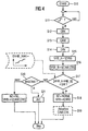
- a step S10 (FIG. 4), the start of a second takes place Program part, which is processed in the control device 2 becomes.
- a step S11 it is checked whether the measurement signal of the camshaft sensor 5 has a flank.
- the camshaft sensor 5 is preferably as a simple Hall sensor with a two-pole magnetic wheel formed on the second Camshaft 112 is arranged. The measuring signal of the camshaft sensor 5 thus provides two signal edges per revolution the second camshaft 112.
- step S11 Indicates the measurement signal of the camshaft sensor 5 in the step If there is no edge on S11, it will be after a specified waiting time the processing continues again in step S1. Otherwise, in steps S12 to S14, the current ones Angle of rotation CRK, CAM, DRV of the crankshaft 13, the second camshaft 112 and the drive shaft 1162 is read.
- a first value VHB_A of the valve lift start becomes the gas exchange valve 12 depending on the angle of rotation DRV of the drive shaft 1162 determined.
- the first value VHB_A preferably depends on a first characteristic curve determined by the rotation angle DRV of the drive shaft 1162.
- a step S16 becomes a second value VHB_B of the valve lift start depending on the rotation angle CAM of the second camshaft and the rotational angle CRK of the crankshaft 13 and determined Although preferably from a first map depending on the Rotation angles CAM, CRK.
- a step S17 it is checked whether the first value VHB_A from the second value VHB_B less than a predetermined one Threshold SW deviates. If this is the case, it will be on one error-free operation of the actuator sensor 3 is closed and in a step S18 the operating state BZ Normal NORM taken.
- the operating state BZ Normal NORM is the valve lift start VHB depends on the rotation angle DRV of the Drive shaft 1162 determined and again preferably out the first characteristic.
- valve lift start VHB is the valve lift curve of the Gas exchange valve 12 characterizing size. Further the Values that characterize valve lift are, for example the valve lift end if the valve lift end is variably adjustable is, or one over the entire opening duration of the Gas exchange valve 12 during a cycle of the internal combustion engine integrated opening area.
- a step S19 can at predetermined intervals an adaptation of the rotation angle CAM, which is detected by the camshaft sensor 5, and the Angle of rotation CRK detected by the crankshaft sensor 4 will be done.
- the rotation angle DRV of the actuator shaft 1162 taking into account the translation of the Worm gear and the current angle CRK the Crankshaft 13 in a desired value of the angle of rotation CAM of second camshaft 112 converted. From the setpoint and the determined by the camshaft sensor 5 rotation angle DRV the second camshaft 112 is then determined a correction value, with the detected by the camshaft sensor 5 rotation angle CAM is corrected.
- a desired value of the rotational angle of the crankshaft 13 dependent from the rotation angle DRV of the drive shaft 1162 and the Rotation angle CAM of the second camshaft 112 can be determined.
- a correction value determined with the angle of rotation CRK of the crankshaft is corrected. So inaccuracies can easily when installing the camshaft sensor 5 or the crankshaft sensor and manufacturing inaccuracies of the crankshaft sensor 4 and the camshaft sensor 5 can be compensated.
- Step S20 checks whether the internal combustion engine is in the State of the start BKSTART is located. If this is the case, then In step S21, the value of the counter k becomes dependent on the rotation angle CRK of the crankshaft 13 and the rotation angle CAM the second camshaft 112 determined. The counter is then set to this value, so initialized. That's easy be avoided that the drive shaft 1162 of the actuator 116 after a start of the internal combustion engine to the given reference point must be driven.
- step S20 If the condition of step S20 is not met, then the Operating status of the BZ of the emergency NL taken.
- the valve lift beginning VHB then becomes dependent on the angles of rotation CAM, CRK of the second camshaft 112 and the crankshaft 13 is determined and preferably from the first map.
- Emergency running NL is then the load control of the internal combustion engine via a load actuator, for example, a throttle is.
- the actuator 16 is then controlled by the controller 2 no longer activated, since the rotation angle DRV the drive shaft is no longer error free from the Stellantriebssersor 3 is detected and thus the timely commutation the armature current is no longer guaranteed.
- Valve lift start VHB From the Valve lift start VHB then becomes a valve lift curve of the Gas-valve characterizing size determined, the then as a correction value in determining a control signal is taken into account for the load actuator. So that's one comfortable emergency running ensures that the driver's request a driver of the motor vehicle with the control device 2 exactly in a corresponding to be delivered by the internal combustion engine Torque can be implemented.
- valve lift beginning VHB also another the valve lift of the gas exchange valve 12 characterizing size are determined and then the processing of steps S15 to S22 based on this Size done.
- the drive shaft is preferred 1162 ensured that the rotation angle CAM, CRK the second camshaft 112 and the crankshaft 13 error-free be detected.
- crankshaft sensor be monitored with the camshaft sensor. It is therefore only necessary, exactly one camshaft sensor for both Provide camshafts.
- Characteristic curves or characteristic diagrams are by investigations at a Engine test bench or determined by driving tests.
Landscapes
- Engineering & Computer Science (AREA)
- Mechanical Engineering (AREA)
- General Engineering & Computer Science (AREA)
- Output Control And Ontrol Of Special Type Engine (AREA)
- Valve Device For Special Equipments (AREA)
- Combined Controls Of Internal Combustion Engines (AREA)
Description
- Figur 1:
- eine erste Ansicht einer Brennkraftmaschine mit einer erfindungsgemäßen Steuereinrichtung 2,
- Figur 2:
- eine zweite Ansicht der Brennkraftmaschine,
- Figur 3:
- ein Ablaufdiagramm eines ersten Teils eines Programms, das in der Steuereinrichtung 2 abgearbeitet wird,
- Figur 4:
- einen zweiten Teil des Programms, das in der Steuereinrichtung 2 abgearbeitet wird.
Claims (11)
- Vorrichtung zum Verstellen des Ventilhubverlaufs eines Gaswechselventils einer Brennkraftmaschine, wobei die Vorrichtung (11) aufweist:dadurch gekennzeichnet,eine erste Nockenwelle (111), die mechanisch mit der Kurbelwelle (13) gekoppelt ist,eine zweite Nockenwelle (112), die mechanisch mit der ersten Nockenwelle (111) gekoppelt ist,einen Stellantrieb (116), der die Phase der zweiten Nockenwelle (112) relativ zu der ersten Nockenwelle (111) einstellt,ein Übertragungsglied (117), das den Hub der Nocken (1111, 1121) der Nockenwellen derart auf das Gaswechselventil (12) überträgt, dass durch den Hubverlauf der ersten Nockenwelle (111) und der zweiten Nockenwelle (112) der Ventilhubverlauf bestimmt ist,einem Kurbelwellensensor (4), der den Drehwinkel (CRK) der Kurbelwelle (13) erfasst, einen Stellantriebssensor (3), der einen Drehwinkel (DRV) des Stellantriebs (116) erfasst, undeiner Steuereinrichtung (2), die ein Stellsignal für den Stellantrieb (116) abhängig von dem Drehwinkel (DRV) des Stellantriebs ermittelt,dass ein Nockenwellensensor (5) vorgesehen ist, der den Drehwinkel (CAM) der zweiten Nockenwelle (112) erfasst, unddass die Steuereinrichtung (2) den Drehwinkel (DRV) des Stellantriebes (116) abhängig von den Drehwinkeln (CAM, CRK) des zweiten Nockenwellensensors (5) und der Kurbelwelle (13) auf ein fehlerhaftes Verhalten überwacht.
- Verfahren zum Steuern einer Vorrichtung zum Verstellen des Ventilhubverlaufs eines Gaswechselventils einer Brennkraftmaschine, wobei die Vorrichtung (11) aufweist:dadurch gekennzeichnet,eine erste Nockenwelle (111), die mechanisch mit der Kurbelwelle (13) gekoppelt ist,eine zweite Nockenwelle (112), die mechanisch mit der ersten Nockenwelle (111) gekoppelt ist,einen Stellantrieb (116), der die Phase der zweiten Nockenwelle (112) relativ zu der ersten Nockenwelle (111) einstellt,ein Übertragungsglied (117), das den Hub der Nocken (1111, 1121) der Nockenwellen derart auf das Gaswechselventil (12) überträgt, dass durch den Hubverlauf der ersten Nockenwelle (111) und der zweiten Nockenwelle (112) der Ventilhubverlauf bestimmt ist,einem Kurbelwellensensor (4), der den Drehwinkel (CRK) der Kurbelwelle (13) erfasst, einen Stellantriebssensor (3), der einen Drehwinkel (DRV) des Stellantriebs (116) erfasst, undeiner Steuereinrichtung (2), die ein Stellsignal für den Stellantrieb (116) abhängig von dem Drehwinkel (DRV) des Stellantriebs ermittelt,dass der Drehwinkel (CAM) der zweiten Nockenwelle (112) mittels eines Nockenwellensensors (5) erfasst wird undder Drehwinkel (DRV) des Stellantriebes (116) abhängig von den Drehwinkels (CAM, CRK) der zweiten Nockenwelle (112) und der Kurbelwelle (13) auf ein fehlerhaftes Verhalten überwacht wird.
- Verfahren nach Anspruch 2, dadurch gekennzeichnet, dass beim Erkennen eines fehlerhaften Drehwinkels (DRV) des Stellantriebs (116) ein Notlauf (NL) gesteuert wird.
- Verfahren nach Anspruch 3, dadurch gekennzeichnet, dass im Notlauf (NL) eine den Ventilhubverlauf charakterisierende Größe abhängig von den Drehwinkeln (CAM, CRK) der zweiten Nockenwelle (112) und der Kurbelwelle (13) ermittelt wird.
- Verfahren nach einem der Ansprüche 3 oder 4, dadurch gekennzeichnet, dass bei dem Überwachen geprüft wird, ob ein erster Wert einer den Ventilhubverlauf charakterisierende Größe, der abhängig von den Drehwinkeln (CAM, CRK) der zweiten Nockenwelle (112) und der Kurbelwelle (13) ermittelt wird, mehr als ein vorgegebener Schwellenwert (SW) von einem zweiten Wert der den Ventilhubverlauf charakterisierenden Größe abweicht, der abhängig von dem Drehwinkel (DRV) der Antriebswelle (1162) ermittelt wird.
- Verfahren nach einem der Ansprüche 4 oder 5, dadurch gekennzeichnet, dass geprüft wird, ob der erste Wert der den Ventilhubverlauf charakterisierenden Größe sich innerhalb eines vorgegebenen Zeitintervalls mehr als ein vorgegebener weiterer Schwellenwert ändert.
- Verfahren nach einem der vorstehenden Ansprüche, dadurch gekennzeichnet, dass die den Ventilhubverlauf charakterisierende Größe der Ventilhubbeginn (VHB) oder das Ventilhubende des Gaswechselventils (12) ist.
- Verfahren nach einem der vorstehenden Ansprüche, dadurch gekennzeichnet, dass der Stellantrieb (116) einen Synchronmotor (1161) umfasst, dessen Stromkommutierung abhängig von dem Drehwinkel (DRV) gesteuert wird, der von dem Stellantriebssensor (3) erfasst wird.
- Verfahren nach einem der Ansprüche 4 bis 8, dadurch gekennzeichnet, dass ein Kalibrieren des Kurbelwellensensors (4) oder des Nockenwellensensors (5) abhängig von dem Drehwinkel (DRV) des Stellantriebs (116) erfolgt.
- Verfahren nach einem der Ansprüche 4 bis 8, dadurch gekennzeichnet, dass der Stellantriebssensor (3) ein Inkrementalgeber ist, und der Drehwinkel (DRV) des Stellantriebs (116) abhängig von den Drehwinkeln (CAM, CRK) der zweiten Nockenwelle (112) und der Kurbelwelle (13) initialisiert wird, wenn beim Überwachen ein fehlerhafter Drehwinkel (DRV) des Stellantriebs (116) erkannt wird und/oder eine vorgegebene Bedingung erfüllt ist.
- Verfahren nach Anspruch 10, dadurch gekennzeichnet, dass die vorgegebene Bedingung ist, dass die Brennkraftmaschine gestartet wird.
Applications Claiming Priority (2)
| Application Number | Priority Date | Filing Date | Title |
|---|---|---|---|
| DE19821241 | 1998-05-12 | ||
| DE19821241 | 1998-05-12 |
Publications (2)
| Publication Number | Publication Date |
|---|---|
| EP0957239A1 EP0957239A1 (de) | 1999-11-17 |
| EP0957239B1 true EP0957239B1 (de) | 2005-02-09 |
Family
ID=7867513
Family Applications (1)
| Application Number | Title | Priority Date | Filing Date |
|---|---|---|---|
| EP99109119A Expired - Lifetime EP0957239B1 (de) | 1998-05-12 | 1999-05-07 | Einrichtung zum Steuern einer Vorrichtung zum Verstellen des Ventilhubverlaufs eines Gaswechselventils einer Brennkraftmaschine |
Country Status (3)
| Country | Link |
|---|---|
| US (1) | US6119641A (de) |
| EP (1) | EP0957239B1 (de) |
| DE (1) | DE59911574D1 (de) |
Families Citing this family (5)
| Publication number | Priority date | Publication date | Assignee | Title |
|---|---|---|---|---|
| DE10018193A1 (de) * | 2000-04-12 | 2001-10-25 | Bayerische Motoren Werke Ag | Regelverfahren |
| DE10028995B4 (de) * | 2000-06-16 | 2005-10-27 | Siemens Ag | Verfahren zur Bewertung der Phasenlage einer Nockenwelle eines Verbrennungsmotors, insbesondere für ein Kraftfahrzeug |
| JP4075811B2 (ja) * | 2004-01-14 | 2008-04-16 | トヨタ自動車株式会社 | 内燃機関の可変動弁機構故障診断装置 |
| JP4269169B2 (ja) * | 2004-08-31 | 2009-05-27 | 株式会社デンソー | 内燃機関の回転状態検出装置 |
| JP2006226226A (ja) * | 2005-02-18 | 2006-08-31 | Toyota Motor Corp | 内燃機関の制御装置 |
Family Cites Families (15)
| Publication number | Priority date | Publication date | Assignee | Title |
|---|---|---|---|---|
| DE3217203A1 (de) * | 1981-05-15 | 1982-12-02 | Honda Giken Kogyo K.K., Tokyo | Variable ventilsteuerung |
| GB9018558D0 (en) * | 1990-08-23 | 1990-10-10 | Ricardo Group Plc | Valve gear for internal combustion engines |
| US5052350A (en) * | 1990-11-02 | 1991-10-01 | King Brian T | Device to combine the motions of two camlobes differentially phased |
| ATE158058T1 (de) * | 1991-04-24 | 1997-09-15 | Donald Charles Wride | Ventilantriebsvorrichtung |
| SE513062C2 (sv) * | 1992-06-30 | 2000-06-26 | Fanja Ltd | Förfarande för styrning av arbetsförloppet i en förbränningskolvmotor samt motor för genomförande av förfarandet |
| DE4244550C2 (de) | 1992-12-30 | 1998-05-28 | Meta Motoren Energietech | Vorrichtung zur Verdrehung von Nockenwellen von Brennkraftmaschinen |
| WO1994016203A1 (de) * | 1992-12-30 | 1994-07-21 | Meta Motoren- Und Energie-Technik Gmbh | Vorrichtung zur variablen steuerung der ventile von brennkraftmaschinen, insbesondere zur drosselfreien laststeuerung von ottomotoren |
| DE4301453C2 (de) * | 1993-01-20 | 1995-01-05 | Meta Motoren Energietech | Variable Ventilsteuerung von Brennkraftmaschinen |
| DE4322480C2 (de) * | 1993-07-06 | 1996-05-02 | Meta Motoren Energietech | Vorrichtung zur variablen Ventilsteuerung von Brennkraftmaschinen |
| DE19501386C2 (de) * | 1995-01-18 | 1998-12-10 | Meta Motoren Energietech | Verfahren zum Steuern einer fremdgezündeten, mit einer Kraftstoffeinspritzanlage ausgerüsteten Kolbenbrennkraftmaschine |
| DE19547101A1 (de) * | 1995-12-16 | 1997-06-19 | Bosch Gmbh Robert | Vorrichtung zum Verstellen einer Nockenwelle einer Brenkraftmaschine |
| DE19650249B4 (de) * | 1996-12-04 | 2006-07-13 | Robert Bosch Gmbh | Einrichtung zur Erfassung des Verdrehwinkels und/oder des Ventilhubes bei einer mehrzylindrigen Brennkraftmaschine |
| DE19701202A1 (de) * | 1997-01-15 | 1998-07-23 | Daimler Benz Ag | Variable Ventilsteuerung für Brennkraftmaschinen |
| DE59803988D1 (de) * | 1997-08-14 | 2002-06-06 | Siemens Ag | Verfahren zur einstellung des ventilhubes |
| DE19747031A1 (de) * | 1997-10-24 | 1999-04-29 | Daimler Chrysler Ag | Variable Ventilsteuerung für Brennkraftmaschinen |
-
1999
- 1999-05-07 DE DE59911574T patent/DE59911574D1/de not_active Expired - Lifetime
- 1999-05-07 EP EP99109119A patent/EP0957239B1/de not_active Expired - Lifetime
- 1999-05-11 US US09/309,961 patent/US6119641A/en not_active Expired - Fee Related
Also Published As
| Publication number | Publication date |
|---|---|
| EP0957239A1 (de) | 1999-11-17 |
| US6119641A (en) | 2000-09-19 |
| DE59911574D1 (de) | 2005-03-17 |
Similar Documents
| Publication | Publication Date | Title |
|---|---|---|
| EP1216352B1 (de) | Verfahren zum steuern einer brennkraftmaschine | |
| DE10080467B4 (de) | Einstellbares Ventiltriebsystem eines Verbrennungsmotors | |
| EP2547876B1 (de) | Verfahren und vorrichtung zum betreiben eines verbrennungsmotors bei einer störung eines kurbelwellensensors | |
| DE69031196T2 (de) | Drosselklappenbetätigungsvorrichtung und Steuerungssystem dafür | |
| EP0445555B1 (de) | Regelverfahren zur drehzahlabhängigen, stufenlosen Verstellung der Nockenspreizung | |
| DE102007000174A1 (de) | Variable Ventilzeitabstimmungsvorrichtung mit verringertem Betriebsgeräusch und deren Steuerverfahren | |
| DE102007000471B4 (de) | Variable Ventilsteuerung für Brennkraftmaschine | |
| EP1281848B1 (de) | Drosselklappenstutzen | |
| DE102008045549B4 (de) | Einstellvorrichtung für eine Ventilzeitsteuerung, die eine Beschädigung von Schaltelementen durch Hitze zuverlässig verhindert | |
| DE102006000026B4 (de) | Variable Ventilzeitsteuereinrichtung | |
| DE102019109473B4 (de) | Regelungsvorrichtung eines Ventilöffnungs-/Schließ-Zeitsteuerungsmechanismus | |
| DE102004031166B4 (de) | Vorrichtung und Verfahren zur Kontrolle einer Motorventilöffnung in einem Verbrennungsmotor | |
| DE10301493B4 (de) | Steuereinrichtung für variablen Ventileinstellmechanismus und zugehöriges Verfahren | |
| DE60201250T2 (de) | Verfahren zur Einstellung von Ventilspielen und Vorrichtung zur Durchführung des Verfahrens | |
| DE4209586A1 (de) | Drosseleinrichtung | |
| DE3918852A1 (de) | Elektrisch ansteuerbare drosselklappenbetaetigungseinrichtung fuer brennkraftmaschinen | |
| DE19731972A1 (de) | Verfahren zum Steuern einer Brennkraftmaschine | |
| DE102004050114B4 (de) | Ventilzeitsteuerungsvorrichtung | |
| DE19650249B4 (de) | Einrichtung zur Erfassung des Verdrehwinkels und/oder des Ventilhubes bei einer mehrzylindrigen Brennkraftmaschine | |
| DE102007000179A1 (de) | Variable Ventilzeitabstimmungsvorrichtung mit verringertem Energieverbrauch und deren Steuerverfahren | |
| EP0957239A1 (de) | Einrichtung zum Steuern einer Vorrichtung zum Verstellen des Ventilhubverlaufs eines Gaswechselventils einer Brennkraftmaschine | |
| EP1573175A1 (de) | Anordnung zum verstellen der drehwinkelrelation zwischen nockenwelle und kurbelwelle | |
| EP1527258A1 (de) | Steuereinrichtung zum verstellen des drehwinkels einer nockenwelle | |
| EP1605140B1 (de) | Verstellvorrichtung für eine Nockenwelle | |
| DE102007000472B4 (de) | Variables Ventilzeitgebungssystem und Verfahren zu dessen Steuerung |
Legal Events
| Date | Code | Title | Description |
|---|---|---|---|
| PUAI | Public reference made under article 153(3) epc to a published international application that has entered the european phase |
Free format text: ORIGINAL CODE: 0009012 |
|
| AK | Designated contracting states |
Kind code of ref document: A1 Designated state(s): DE FR GB SE |
|
| AX | Request for extension of the european patent |
Free format text: AL;LT;LV;MK;RO;SI |
|
| 17P | Request for examination filed |
Effective date: 19991206 |
|
| AKX | Designation fees paid |
Free format text: DE FR GB SE |
|
| 17Q | First examination report despatched |
Effective date: 20020806 |
|
| GRAP | Despatch of communication of intention to grant a patent |
Free format text: ORIGINAL CODE: EPIDOSNIGR1 |
|
| GRAS | Grant fee paid |
Free format text: ORIGINAL CODE: EPIDOSNIGR3 |
|
| GRAA | (expected) grant |
Free format text: ORIGINAL CODE: 0009210 |
|
| AK | Designated contracting states |
Kind code of ref document: B1 Designated state(s): DE FR GB SE |
|
| PG25 | Lapsed in a contracting state [announced via postgrant information from national office to epo] |
Ref country code: GB Free format text: LAPSE BECAUSE OF FAILURE TO SUBMIT A TRANSLATION OF THE DESCRIPTION OR TO PAY THE FEE WITHIN THE PRESCRIBED TIME-LIMIT Effective date: 20050209 |
|
| REG | Reference to a national code |
Ref country code: GB Ref legal event code: FG4D Free format text: NOT ENGLISH |
|
| REF | Corresponds to: |
Ref document number: 59911574 Country of ref document: DE Date of ref document: 20050317 Kind code of ref document: P |
|
| PG25 | Lapsed in a contracting state [announced via postgrant information from national office to epo] |
Ref country code: SE Free format text: LAPSE BECAUSE OF FAILURE TO SUBMIT A TRANSLATION OF THE DESCRIPTION OR TO PAY THE FEE WITHIN THE PRESCRIBED TIME-LIMIT Effective date: 20050509 |
|
| GBV | Gb: ep patent (uk) treated as always having been void in accordance with gb section 77(7)/1977 [no translation filed] |
Effective date: 20050209 |
|
| PLBE | No opposition filed within time limit |
Free format text: ORIGINAL CODE: 0009261 |
|
| STAA | Information on the status of an ep patent application or granted ep patent |
Free format text: STATUS: NO OPPOSITION FILED WITHIN TIME LIMIT |
|
| ET | Fr: translation filed | ||
| 26N | No opposition filed |
Effective date: 20051110 |
|
| REG | Reference to a national code |
Ref country code: FR Ref legal event code: ST Effective date: 20100129 |
|
| PG25 | Lapsed in a contracting state [announced via postgrant information from national office to epo] |
Ref country code: FR Free format text: LAPSE BECAUSE OF NON-PAYMENT OF DUE FEES Effective date: 20090602 |
|
| PGFP | Annual fee paid to national office [announced via postgrant information from national office to epo] |
Ref country code: FR Payment date: 20080526 Year of fee payment: 10 |
|
| PGFP | Annual fee paid to national office [announced via postgrant information from national office to epo] |
Ref country code: DE Payment date: 20170531 Year of fee payment: 19 |
|
| REG | Reference to a national code |
Ref country code: DE Ref legal event code: R119 Ref document number: 59911574 Country of ref document: DE |
|
| PG25 | Lapsed in a contracting state [announced via postgrant information from national office to epo] |
Ref country code: DE Free format text: LAPSE BECAUSE OF NON-PAYMENT OF DUE FEES Effective date: 20181201 |