EP0957255A2 - Verfahren und Vorrichtung zur Steuerung einer Brennkraftmaschine - Google Patents
Verfahren und Vorrichtung zur Steuerung einer Brennkraftmaschine Download PDFInfo
- Publication number
- EP0957255A2 EP0957255A2 EP99104636A EP99104636A EP0957255A2 EP 0957255 A2 EP0957255 A2 EP 0957255A2 EP 99104636 A EP99104636 A EP 99104636A EP 99104636 A EP99104636 A EP 99104636A EP 0957255 A2 EP0957255 A2 EP 0957255A2
- Authority
- EP
- European Patent Office
- Prior art keywords
- value
- exhaust gas
- actuator
- setpoint
- actual
- Prior art date
- Legal status (The legal status is an assumption and is not a legal conclusion. Google has not performed a legal analysis and makes no representation as to the accuracy of the status listed.)
- Withdrawn
Links
- 238000002485 combustion reaction Methods 0.000 title claims abstract description 17
- 238000000034 method Methods 0.000 title claims description 23
- 238000012937 correction Methods 0.000 claims description 20
- 238000005259 measurement Methods 0.000 claims description 2
- 230000006698 induction Effects 0.000 abstract 1
- 239000000203 mixture Substances 0.000 abstract 1
- 239000007789 gas Substances 0.000 description 82
- 239000000446 fuel Substances 0.000 description 24
- 230000006978 adaptation Effects 0.000 description 7
- 230000001276 controlling effect Effects 0.000 description 6
- 230000001105 regulatory effect Effects 0.000 description 5
- 230000001419 dependent effect Effects 0.000 description 4
- 238000011161 development Methods 0.000 description 4
- 230000018109 developmental process Effects 0.000 description 4
- 238000010586 diagram Methods 0.000 description 4
- 230000006399 behavior Effects 0.000 description 3
- 108010083018 monocyte locomotion inhibitory factor Proteins 0.000 description 2
- 239000000654 additive Substances 0.000 description 1
- 230000000996 additive effect Effects 0.000 description 1
- 230000015572 biosynthetic process Effects 0.000 description 1
- 238000013461 design Methods 0.000 description 1
- 230000015654 memory Effects 0.000 description 1
- 239000007787 solid Substances 0.000 description 1
- 230000001960 triggered effect Effects 0.000 description 1
Images


Classifications
-
- F—MECHANICAL ENGINEERING; LIGHTING; HEATING; WEAPONS; BLASTING
- F02—COMBUSTION ENGINES; HOT-GAS OR COMBUSTION-PRODUCT ENGINE PLANTS
- F02D—CONTROLLING COMBUSTION ENGINES
- F02D41/00—Electrical control of supply of combustible mixture or its constituents
- F02D41/0025—Controlling engines characterised by use of non-liquid fuels, pluralities of fuels, or non-fuel substances added to the combustible mixtures
- F02D41/0047—Controlling exhaust gas recirculation [EGR]
- F02D41/0065—Specific aspects of external EGR control
- F02D41/0072—Estimating, calculating or determining the EGR rate, amount or flow
-
- F—MECHANICAL ENGINEERING; LIGHTING; HEATING; WEAPONS; BLASTING
- F02—COMBUSTION ENGINES; HOT-GAS OR COMBUSTION-PRODUCT ENGINE PLANTS
- F02D—CONTROLLING COMBUSTION ENGINES
- F02D41/00—Electrical control of supply of combustible mixture or its constituents
- F02D41/02—Circuit arrangements for generating control signals
- F02D41/18—Circuit arrangements for generating control signals by measuring intake air flow
-
- F—MECHANICAL ENGINEERING; LIGHTING; HEATING; WEAPONS; BLASTING
- F02—COMBUSTION ENGINES; HOT-GAS OR COMBUSTION-PRODUCT ENGINE PLANTS
- F02D—CONTROLLING COMBUSTION ENGINES
- F02D41/00—Electrical control of supply of combustible mixture or its constituents
- F02D41/24—Electrical control of supply of combustible mixture or its constituents characterised by the use of digital means
- F02D41/2406—Electrical control of supply of combustible mixture or its constituents characterised by the use of digital means using essentially read only memories
- F02D41/2425—Particular ways of programming the data
- F02D41/2429—Methods of calibrating or learning
- F02D41/2451—Methods of calibrating or learning characterised by what is learned or calibrated
-
- F—MECHANICAL ENGINEERING; LIGHTING; HEATING; WEAPONS; BLASTING
- F02—COMBUSTION ENGINES; HOT-GAS OR COMBUSTION-PRODUCT ENGINE PLANTS
- F02D—CONTROLLING COMBUSTION ENGINES
- F02D41/00—Electrical control of supply of combustible mixture or its constituents
- F02D41/24—Electrical control of supply of combustible mixture or its constituents characterised by the use of digital means
- F02D41/2406—Electrical control of supply of combustible mixture or its constituents characterised by the use of digital means using essentially read only memories
- F02D41/2425—Particular ways of programming the data
- F02D41/2429—Methods of calibrating or learning
- F02D41/2441—Methods of calibrating or learning characterised by the learning conditions
-
- F—MECHANICAL ENGINEERING; LIGHTING; HEATING; WEAPONS; BLASTING
- F02—COMBUSTION ENGINES; HOT-GAS OR COMBUSTION-PRODUCT ENGINE PLANTS
- F02D—CONTROLLING COMBUSTION ENGINES
- F02D41/00—Electrical control of supply of combustible mixture or its constituents
- F02D41/24—Electrical control of supply of combustible mixture or its constituents characterised by the use of digital means
- F02D41/2406—Electrical control of supply of combustible mixture or its constituents characterised by the use of digital means using essentially read only memories
- F02D41/2425—Particular ways of programming the data
- F02D41/2429—Methods of calibrating or learning
- F02D41/2451—Methods of calibrating or learning characterised by what is learned or calibrated
- F02D41/2474—Characteristics of sensors
-
- Y—GENERAL TAGGING OF NEW TECHNOLOGICAL DEVELOPMENTS; GENERAL TAGGING OF CROSS-SECTIONAL TECHNOLOGIES SPANNING OVER SEVERAL SECTIONS OF THE IPC; TECHNICAL SUBJECTS COVERED BY FORMER USPC CROSS-REFERENCE ART COLLECTIONS [XRACs] AND DIGESTS
- Y02—TECHNOLOGIES OR APPLICATIONS FOR MITIGATION OR ADAPTATION AGAINST CLIMATE CHANGE
- Y02T—CLIMATE CHANGE MITIGATION TECHNOLOGIES RELATED TO TRANSPORTATION
- Y02T10/00—Road transport of goods or passengers
- Y02T10/10—Internal combustion engine [ICE] based vehicles
- Y02T10/40—Engine management systems
Definitions
- the invention relates to a method and a device for controlling an internal combustion engine according to the General terms of the independent claims.
- a method and an apparatus for controlling a Internal combustion engines are known from DE 195 200 39. There are a method and a device for control an internal combustion engine with an actuator for influencing described the amount of recirculated exhaust gas. An actual size is compared with a target size. Starting from this Comparison will be an actuator that returns the share of returned Exhaust gas influenced, controlled. When setting up according to State of the art, the quantity of air, especially the fresh air intake. This with one of the working point of the internal combustion engine dependent setpoint compared. The system deviation regulates preferably a PI controller.
- the proportions are of fresh air and the proportions of recirculated exhaust gas small.
- the proportions of recirculated exhaust gas small.
- a fresh air volume flow of 950 kg / h an exhaust gas mass flow of 50 kg / h is added and the sensor that measures the amount of fresh air has one Tolerance of +/- 5%, so an actual Fresh air volume flow of approx. 900 kg / h or 1000 kg / h measured. Because the sum enforced by the engine Fresh air mass flow and recirculated exhaust gas mass flow remains approximately constant, this leads to a return Exhaust gas flow of 0 kg / h or 100 kg / h.
- the invention is based, with one Method and device for controlling a Internal combustion engine of the type mentioned the emissions to reduce.
- the accuracy of the Regulation of the exhaust gas recirculation rate or the proportion recirculated exhaust gas can be improved.
- the emissions be reduced. This is done by regulating the Share of recirculated exhaust gas. This means small ones Exhaust gas recirculation rates affect the system tolerances that the Change the amount of fresh air, very little on the Exhaust gas recirculation rate off.
- the first reading is with the actuator open and the second measured value at closed actuator detected.
- the measured value and the first measured value can be the actual value in calculate easily. It is particularly advantageous that the map values can be adapted.
- a particularly advantageous embodiment results if in certain operating states both measured values are recorded and determined from these correction values and in one Map are filed. These correction values can then to correct the actual value or the setpoint of the controller be used.
- a particularly advantageous embodiment provides that Control signal for the actuator is modulated such that it alternately occupies its first and second position. At In this embodiment, no map memories are used needed.
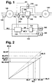
- FIG. 1 shows a schematic representation of the invention Control
- Figure 2 is a map showing the relationship between the amount of air and the output signal of a 3 shows a block diagram of an air flow meter first embodiment
- Figure 4 is a block diagram of a second embodiment
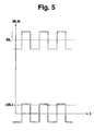
- Figure 5 different signals at the embodiment according to FIG. 3 or according to FIG. 4 occur
- Figures 6 and 7 show further refinements of the device according to the invention.
- FIG. 1 the device for controlling a Internal combustion engine 100 shown.
- the air gets over a feed line 105 to the internal combustion engine 100
- Exhaust line 110 releases exhaust gases.
- a return line 115 connects the exhaust pipe 110 to the supply pipe 105.
- a compressor 125 can be arranged in the feed line be that compresses the supplied air.
- the compressor 125 is by a turbine arranged in the exhaust pipe 110 140 driven.
- a throttle valve actuator 130 which controls a throttle valve, the intake Fresh air volume varies.
- the throttle valve actuator 130 is also referred to as a second actuator.
- the amount of fresh air MLI supplied is determined by means of a Sensor 135 detects, which is also referred to as an air flow meter becomes.
- a controller 150 acts on the throttle valve actuator 130 with a drive signal AD, one Fuel flow regulator 145 with a signal QK and that Exhaust gas recirculation valve 120 with a signal AV.
- the Exhaust gas recirculation valve includes an electropneumatic Converter that converts the control signal AV into a pneumatic Force and thus in a certain position of the actuator 120 implemented.
- the controller 150 evaluates the output signals a speed sensor 165, an accelerator pedal position sensor 160, the air flow meter 135 and possibly further signals from other sensors, for example one Accelerator pedal position sensor 160, off.
- the output signal FP of the accelerator position transmitter 160 and the speed signal N of the speed sensor 165 are from a Fuel control 152 processed, which then the Fuel quantity adjuster 145 with the control signal QK acted upon. Furthermore, the fuel quantity control 152 a signal MLS regarding the setpoint for the air volume and the fuel quantity signal QK to one Exhaust gas recirculation control 154 continues. The Exhaust gas recirculation control 154 also processes this Output signal MLI of the air flow meter 135. Die Exhaust gas recirculation control 154 provides the signal AV and that Signal AD available.
- the over the Supply line 105 is supplied fresh air from the Compressor 125 compresses.
- the Throttle actuator 130 may be the throttle be controlled that the amount of air supplied is throttled or throttled to internal combustion engine 100.
- the Exhaust gases that are discharged via the exhaust line 110 drive turbine 140, which in turn compressors 125 drives.
- the fuel quantity control 152 calculates based on Driver request FP, for example by means of Accelerator pedal position sensor 160 is detected, the speed N and possibly other operating parameters, a control signal QK, the determines the amount of fuel to be injected. With this The fuel quantity adjuster 145 is activated in a signal. The fuel control 152 also outputs a setpoint MLS the amount of fresh air. This setpoint corresponds to the desired amount of air to burn the QK fuel quantity is required.
- the Exhaust gas recirculation control 154 controls the throttle valve actuator 130, the exhaust gas recirculation valve 120 so that the Fuel in the internal combustion engine with the lowest possible Emissions burns.
- FIG. 2 shows a map of the air flow meter 135 applied. That is above the real air volume MLR Output signal MLM of the air flow sensor 135 plotted. With a solid line the connection is at a tolerance-free sensor and with a corresponding one dashed line the context of a tolerance sensor shown. With completely air volume MLAZ reaches the closed actuator Internal combustion engine. This leads to a tolerance-free sensor an output signal MLHFZ. These relationships are with represented by a solid line.
- ⁇ MLS is a measure of the air mass difference.
- the air mass actually supplied gives way significantly from the expected value. For example a setpoint is given that the sensor signal MLHFAZ corresponds, so only the one with a vertical dashed line shown air volume MLIF measured. This air volume MLIF is significantly smaller than the expected value MLI with a tolerance-free sensor.
- the air mass difference is determined by the fact that the actuator is temporarily completely is closed, in this state a measured value MLHF ' is measured, which occurs when the actuator is closed. Furthermore, the actuator is temporarily opened Condition brought in which a first measured value MLHFA 'is measured which corresponds to the amount of air when the actuator is open. This variable is sent to a control loop as the actual variable or serves to form a correction value.
- the difference ⁇ MLS of these two measured values corresponds approximately to that recirculated exhaust gas quantity. This is the case if the Gas throughput, consisting of fresh air and exhaust gas not from depends on the exhaust gas recirculation rate.
- the influence of To minimize the tolerance of the sensor 135 Modulation method used The exhaust gas recirculation controller is alternately controlled so that exhaust gas recirculation done, d. H. the exhaust gas recirculation valve 120 is open and that there is no exhaust gas recirculation, d. H. the Exhaust gas recirculation actuator is closed.
- the resulting one Airflow difference between this first position at which the exhaust gas recirculation valve is open, and this second Position at which the exhaust gas recirculation valve is closed, corresponds approximately to the amount of exhaust gas recirculated, because the less that flows into the engine with exhaust gas recirculation Amount of gas is filled with exhaust gas.
- the control loop controls the air volume difference.
- the setpoint generator 300 outputs from various Operating parameters that are not shown, the setpoint ⁇ MLS for the air mass difference.
- the setpoint ⁇ MLS for the air mass difference reaches a connection point 305, at its second input with the negative sign the Actual value ⁇ MLI for the air mass difference is present.
- the output signal of node 305 arrives at a Controller 310.
- the controller 310 is in the essential to that known from the prior art Regulator for regulating the exhaust gas recirculation rate. It can be provided that this also several actuators such for example an exhaust gas recirculation valve and / or Throttle valve controlled.
- the output signal from the controller reaches a Modulation point 315, at the second input of which Output signal of the modulation specification 320 is present.
- the Modulation 315 preferably combines the two signals multiplicative and acts on the actuator 120 corresponding control signals.
- Control signals are a certain real amount of air MLR, which is fed to the internal combustion engine. This is detected by the sensor 135 and in an output signal MLM converted.
- This output signal MLM of the air quantity sensor 135 reaches a rectifier 360 via a high pass 350 and a low pass 370. At the exit of the low pass 370 is the actual value ⁇ MLI for the air mass difference.
- the setpoint generator 300 calculates the setpoint ⁇ MLS in Dependence on different operating conditions. As Operating conditions are particularly the injected Fuel quantity QK, the engine speed N or a size and size corresponding to these sizes if necessary, other sizes are taken into account. This Setpoint value ⁇ MLS is compared with the actual value ⁇ MLI and the Controller 310 fed. This is calculated from the difference a manipulated variable in the form of an amplitude that with the Initial value of the modulation specification is preferred is multiplied.
- the modulation specification 320 provides an alternating one Signal between 0 and 1 with a Frequency F oscillates.
- the value 0 corresponds to a manipulated variable, that does not result in exhaust gas recirculation. This means at Such a signal is sent to an exhaust gas recirculation valve given that this remains closed and that no exhaust gas from the exhaust side to the fresh air side.
- the value 1 has the consequence that the actuator with such a signal is charged that he takes a position that the results in maximum exhaust gas recirculation.
- the resulting air volume MLR is from that Tolerant actuator 135 measured as air value MLM.
- the high pass suppresses the DC component of the signal.
- rectifier 360 and low pass 370 finally the actual variable ⁇ MLI is obtained as the output signal.
- FIG. 3 A further embodiment of this is shown in FIG Embodiment shown. Already described in Figure 3 Elements are identified by corresponding reference symbols.
- This configuration differs from the configuration according to FIG. 3 essentially by the modulation or Demodulation of the signals.
- the measured value MLM of the sensor 135 reaches demodulation via a connection point 410 400, at whose output the actual value ⁇ MLI is present.
- the Modulation specification 420 acts on a limiter 440, whose output signal goes to modulation 315. Further the modulation specification 420 applies a correction 430, which in turn acts on node 410.
- the modulation specification provides a signal that is between the Values -1 and +1 alternate.
- Limiter 440 limits this Output signal of the modulation to values between 0 and 1.
- the signal is demodulated by multiplication of the output signal of the modulation specification 420 with the Output signal of the sensor 135. This is also the Output signal of the modulation specification 420 with the correction 430 out of phase according to the dynamics of the lines.
- Demodulation 400 essentially comprises a low pass, which suppresses high-frequency components.
- the actuator 120 is clocked in this way controlled that it alternately opened and completely closed is.
- a first measured value is obtained detected.
- the actuator closed i.e. H. there is no Exhaust gas recirculation, a second measured value is recorded. The The difference between the two measured values is the actual variable to the controller 310 fed.
- the output signal of the controller is combined with the signal of the Modulation specification 320 linked.
- the actuator 120 is with a signal with a fixed frequency and one from the comparison between the actual value and the setpoint-dependent amplitude acted upon.
- FIGS Figures 6 and 7 Another embodiment of the invention is shown in FIGS Figures 6 and 7 shown.
- the design according to Figure 6 is also the air mass difference as Controlled variable used.
- the quantity of air is used as the control variable, with the Air volume setpoint is corrected accordingly.
- MLHFZ Based on the measured value MLHFA and the stored values MLHFZ then becomes the value ⁇ MLI for the Air mass difference determined. It is particularly advantageous if values for the air volume MLHFZ without exhaust gas recirculation several working points can be measured.
- Several Working points and the corresponding air volume values define support points in at least one or two Levels. The values are preferably determined using a Map adaptation adapted. A corresponding procedure is known from DE-OS 195 28 696.
- FIG. 6a An embodiment of this embodiment is in Figure 6a shown. Already described in previous figures Elements are identified by corresponding reference symbols.
- the output signal from sensor 135 arrives via Switching means 650 to node 605. That Switching means 650 optionally connects the output signal of the Sensor 135 or the output signal of a Constant value specification 655 with node 605.
- the output signal 135 also passes through a switching means 615 to a first PT1 element 610, via a switching means 625 to a second PT1 link 620 and another Switching means 635 to a third PT1 element 630.
- the PT1 elements 610, 620 and 630 act on a map 600 with Signals.
- the map 600 also becomes the output signal of the speed sensor 152 and the output signal QK Quantity specification 152 supplied.
- the switching means 615, 625, 635 and 650 are from one Logic 640 triggered.
- the logic processes in particular the signals of a speed sensor 165 and the quantity specification 152.
- the controller 310 is correspondingly as in the embodiments according to FIGS. 3 and Figure 4 shows the difference between the target value ⁇ MLS and the Actual value ⁇ MLI supplied for the air mass difference.
- the Actual value ⁇ MLI for the air mass difference is based on the difference between the output signal of the sensor 135 and the value MLEB stored in the map 600 certainly.
- the map value MLEB corresponds to that of the present Operating conditions resulting air volume value, which is without exhaust gas recirculation.
- the value is MLHFA it is the value for the amount of air that deals with Exhaust gas recirculation sets. Starting from these two The difference is the value ⁇ MLI for the current air mass difference.
- each and one Air volume value define a point on a plane.
- Three such operating points with the corresponding associated Air volume values define three support points, which in turn define a level. If one of these three is present The respective air volume value is used as a reference point detected. Through this level every operating point becomes one Air volume value assigned.
- An operating point becomes preferably by the speed of the internal combustion engine and defines the amount of fuel injected QK.
- the logic 640 recognizes on the basis of the speed N and injected fuel quantity QK, which operating condition is present. If none of the operating states exist, the one Define the base of the level, the switching means 615, 625, 630 and 650 in that shown in Figure 6a Position controlled.
- the measured air volume value arrives immediately to node 605 and then via the link point 305 to the controller 310 for the Exhaust mass.
- the map 600 calculates the corresponding Air volume MLEB, which is when closed Exhaust gas recirculation valve would result.
- Junction 605 links these two signals and forms an actual value ⁇ MLI for the air mass difference.
- the measured air volume value is used for adaptation.
- the closed Exhaust gas recirculation valve measured air volume values are each around the relevant support point with the associated one Filtered PT1 element 610, 620 or 630.
- the base is recalculated for the map 600 or an adaptation of the follows Map. If this is the case, it is ensured that either the output signal of controller 310 remains constant, the control deviation, d. H. the input signal of the controller 310 becomes 0, the air quantity value becomes large, so that the Controller closes the actuator for exhaust gas recirculation, none Exhaust gas recirculation takes place, or that several of these Opportunities exist together.
- Logic 640 switches the airflow signal from sensor 135 either to a control branch in which the switching means 650 is closed, or an adaptation branch in which the Switching means 650 opened and at least one of the Switching means 615, 625 or 635 is closed.
- the control branch subtracts the measured air volume value MLHFA from the comparison value MLEB, which is derived from that in the characteristic diagram 600 filed level depending on the injected Fuel quantity and speed is calculated. This one The actual value of the air mass difference obtained is calculated using a Working point dependent setpoint ⁇ MLS compared and the Controller 310 supplied.
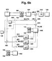
- FIG. 6b A particularly advantageous development of the above Embodiment is shown in Figure 6b.
- a disadvantage of The embodiment of Figure 6a is that the air mass only linear over the fuel quantity QK and the speed N im Map 600 can be learned.
- the development of Figure 6b a difference to one usual air mass stored. This usual air mass is dependent on the fuel quantity in a map 670 QK and the speed N filed.
- FIG. 6b differs in essential of Figure 6a in that the output signal of the sensor 135 via a connection point 660 to the Switching means 615, 625 and 635 arrives and that Output signal MLEB of the map 600 passes through a Node 665 to node 606 of the Corresponds to node 605 in Figure 6a.
- the output signal map 670 based on various parameters can be corrected. These are, for example different pressure and temperature values.
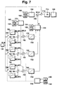
- a setpoint generator 700 evaluates the signals of the Speed sensor 165 and the fuel quantity specification 152.
- the setpoint generator 700 corresponds essentially to that Setpoint generator 300.
- the setpoint generator 700 gives in In contrast to the setpoint generator 300, a setpoint for the Air volume MLS before. Arrived via node 705 this to a further connection point 710.
- Das Output signal of node 710 arrives at a Controller 715, which corresponds essentially to controller 310.
- a Correction value K on which is from a correction map 720 is provided.
- the output signal of the air flow meter 135 also arrives via a switching means 790 to a PT1 element 780, to one PT1 link 781 or is not forwarded. From the PT1 links 780 and 781 succeeded in a connection point 760. The two signals are in node 760 subtracted from each other and arrive at a size ⁇ MLI another node 750, at its second input the output signal of a setpoint specification 770 is present.
- This Setpoint specification 770 essentially corresponds to that Setpoint specification 300 and provides an output signal with respect the setpoint for the air mass difference.
- the output signal of the air flow meter 135 also arrives via a switching means 792 to a PT1 element 782, to a PT1 link 783 or is not forwarded. From the PT1 links 782 and 783 succeeded in a connection point 762. The two signals are in node 762 subtracted from each other and arrive at the value ⁇ MLI another node 750, at its second input the output signal of a setpoint specification 770 is present.
- the output signal of the air flow meter 135 also arrives via a switching means 794 to a PT1 element 784, to one PT1 link 785 or is not forwarded. From the PT1 links 784 and 785 succeeded in a connection point 764. At node 764, the two signals subtracted from each other and arrive at the size ⁇ MLI another node 750, at its second input the output signal of a setpoint specification 770 is present.
- the output signal of node 750 passes through a switching means 740 to a controller 730, which in turn the Correction field 720 applied with signals.
- the switching means 790, 792, 794, 740, 742 and 744 are from logic 795, depending on operating parameters like that Speed and the amount of fuel injected QK controlled.
- the amount of air is used as a controlled variable used.
- the Air quantity setpoint via at least one correction level 720 is modified.
- the actual air volume value accordingly be modified or the control deviation, d. H. modified the input signal of the PI controller 715 become.
- the at least one correction level is defined by at least one three support points determined.
- the bases are that Result of using at least an integral behavior having setpoint controller for the Air mass difference.
- the setpoints for this regulation are specified by the map 770.
- the actual value of the Air mass difference is calculated from the air volume values open and closed exhaust gas recirculation valve determined.
- the correction values is as follows proceeded. If one of the three operating points is reached, that defines a support point of the characteristic diagram 720, so the corresponding switching means 790 and 740, 792 and 742, 794 and 744 controlled so that the corresponding Adaptation branch is active. At node 750, 752, 754 the deviation of the air mass difference ⁇ MLI from her Setpoint ⁇ MLS determined. The corresponding controller 730, 732 or 734 determines a correction value K that is in the map 720 is filed. With this correction value the Setpoint, the actual value or the control deviation of the Airflow controller corrected.
- Logic 795 determines depending on at least the speed N and the amount of fuel injected QK when the Switching means 790, 792, 794 can be controlled to the Air volume value for the closed exhaust gas recirculation and to measure open exhaust gas recirculation. Furthermore, the Logic when the switching means 740, 742 and 744 are activated to determine the values for the support points, and which integrator 730, 732 and 734 is active.
- Link point 710 determines predetermined setpoint MLS the control deviation for the air volume.
- Controller 715 which is preferably Has proportional and integral (PI) behavior Control signal for controlling the actuator 120.
Landscapes
- Engineering & Computer Science (AREA)
- Chemical & Material Sciences (AREA)
- Combustion & Propulsion (AREA)
- Mechanical Engineering (AREA)
- General Engineering & Computer Science (AREA)
- Output Control And Ontrol Of Special Type Engine (AREA)
- Electrical Control Of Air Or Fuel Supplied To Internal-Combustion Engine (AREA)
- Combined Controls Of Internal Combustion Engines (AREA)
- Exhaust-Gas Circulating Devices (AREA)
Abstract
Description
Claims (10)
- Verfahren zur Steuerung einer Brennkraftmaschine mit einem Steller zur Beeinflussung der Menge an rückgeführtem Abgas, wobei eine Istgröße bestimmt wird, die die Menge an rückgeführtem Abgas kennzeichnet, wobei diese Istgröße mit einer Sollgröße verglichen und ausgehend von diesem Vergleich eine Stellgröße zur Ansteuerung des Stellers bestimmt wird, dadurch gekennzeichnet, daß ein erster Meßwert in einer ersten Position (geöffnet) des Stellers und ein zweiter Meßwert in einer zweiten Position (geschlossen) des Stellers erfaßt wird, wobei ausgehend von der Differenz der beiden Meßwerte die Istgröße oder ein Korrekturwert vorgebbar ist.
- Verfahren nach Anspruch 1, dadurch gekennzeichnet, daß der zweite Meßwert bei Vorliegen bestimmter Betriebszustände ermittelt und in einem Kennfeld abgelegt wird.
- Verfahren nach Anspruch 1 oder 2, dadurch gekennzeichnet, daß die Differenz zwischen dem ersten Meßwert und dem abhängig von Betriebskenngrößen aus dem Kennfeld ausgelesenen zweiten Meßwert als Istwert verwendet wird.
- Verfahren nach einem der vorhergehenden Ansprüche, dadurch gekennzeichnet, daß der erste und der zweite Meßwert bei Vorliegen bestimmter Betriebszustände ermittelt wird und daß ausgehend von dem Vergleich der beiden Meßwerte Korrekturwerte in einem Kennfeld abgelegt werden.
- Verfahren nach Anspruch 4, dadurch gekennzeichnet, daß abhängig vom Betriebszustand aus dem Kennfeld Korrekturwerte zur Korrektur eines Sollwertes oder eines Istwertes eines Luftmengenreglers ausgelesen werden.
- Verfahren nach Anspruch 1, dadurch gekennzeichnet, daß der Steller derart getaktet angesteuert wird, daß er abwechselnd seine erste und seine zweite Position einnimmt.
- Verfahren nach Anspruch 6, dadurch gekennzeichnet, daß ausgehend von dem Vergleich zwischen dem Istwert und dem Sollwert ein Signal mit fester Frequenz und einer von dem Vergleich zwischen dem Istwert und Sollwert abhängigen Amplitude vorgebbar ist.
- Verfahren nach einem der Ansprüche 6 oder 7, dadurch gekennzeichnet, daß ausgehend von dem Vergleich zwischen dem Istwert und dem Sollwert ein Faktor bestimmt wird, mit dem das Ausgangssignal einer Modulationsvorgabe multipliziert wird.
- Verfahren nach einem der Ansprüche 6 bis 8, dadurch gekennzeichnet, daß der Signalgenerator ein Signal mit einer festen Frequenz und Amplitude vorgibt.
- Vorrichtun zur Steuerung einer Brennkraftmaschine mit einem Steller zur Beeinflussung der Menge an rückgeführtem Abgas, mit Mitteln zur Bestimmung einer Istgröße, die die Menge an rückgeführtem Abgas kennzeichnet, mit Vergleichsmitteln, die diese Istgröße mit einer Sollgröße vergleichen und einem Regler, der ausgehend von diesem Vergleich eine Stellgröße zur Ansteuerung des Stellers bestimmt, dadurch gekennzeichnet, daß Mittel vorgesehen sind, die einen ersten Meßwert in einer ersten Position (geöffnet) des Stellers und einen zweiten Meßwert in einer zweiten Position (geschlossen) des Stellers erfassen und ausgehend von der Differenz der beiden Meßwerte die Istgröße oder ein Korrekturwert vorgeben.
Applications Claiming Priority (2)
| Application Number | Priority Date | Filing Date | Title |
|---|---|---|---|
| DE19820904 | 1998-05-09 | ||
| DE19820904 | 1998-05-09 |
Publications (2)
| Publication Number | Publication Date |
|---|---|
| EP0957255A2 true EP0957255A2 (de) | 1999-11-17 |
| EP0957255A3 EP0957255A3 (de) | 2001-03-28 |
Family
ID=7867300
Family Applications (1)
| Application Number | Title | Priority Date | Filing Date |
|---|---|---|---|
| EP99104636A Withdrawn EP0957255A3 (de) | 1998-05-09 | 1999-03-09 | Verfahren und Vorrichtung zur Steuerung einer Brennkraftmaschine |
Country Status (3)
| Country | Link |
|---|---|
| EP (1) | EP0957255A3 (de) |
| JP (1) | JP2000002127A (de) |
| DE (1) | DE19920498A1 (de) |
Cited By (2)
| Publication number | Priority date | Publication date | Assignee | Title |
|---|---|---|---|---|
| EP1052387A3 (de) * | 1999-05-08 | 2002-05-02 | DEUTZ Aktiengesellschaft | Verfahren zum Betreiben einer Abgasrückführeinrichtung einer Brennkraftmaschine |
| FR2944059A1 (fr) * | 2009-04-02 | 2010-10-08 | Renault Sas | Procede et systeme de correction d'une mesure de debit d'air admis dans un moteur a combustion interne |
Families Citing this family (9)
| Publication number | Priority date | Publication date | Assignee | Title |
|---|---|---|---|---|
| DE10144337B4 (de) * | 2001-09-10 | 2007-04-19 | Siemens Ag | Adaptives Regelverfahren |
| DE10146317A1 (de) | 2001-09-20 | 2003-04-10 | Bosch Gmbh Robert | Verfahren und Vorrichtung zur Steuerung einer Brennkraftmaschine |
| DE10235531A1 (de) * | 2002-08-03 | 2004-02-19 | Daimlerchrysler Ag | Verfahren zur Ladedruckregelung eines Verbrennungsmotors |
| DE10260322A1 (de) * | 2002-12-20 | 2004-07-08 | Volkswagen Ag | Verfahren und Vorrichtung zur Bestimmung des Abgasrückführmassenstroms eines Verbrennungsmotors |
| FR2860268B1 (fr) * | 2003-09-25 | 2007-05-11 | Renault Sa | Procede et dispositif de controle du fonctionnement d'un moteur a allumage par compression de vehicule automobile, suralimente en air |
| DE102004035316B4 (de) | 2004-07-21 | 2018-10-18 | Robert Bosch Gmbh | Verfahren und Vorrichtung zur Steuerung einer Brennkraftmaschine |
| DE102004035317B4 (de) * | 2004-07-21 | 2020-10-01 | Robert Bosch Gmbh | Verfahren und Vorrichtung zur Steuerung einer Brennkraftmaschine |
| JP5218536B2 (ja) * | 2010-12-10 | 2013-06-26 | 株式会社デンソー | 制御装置 |
| DE102019214880A1 (de) * | 2019-09-27 | 2021-04-01 | Zf Friedrichshafen Ag | Verfahren zum Überprüfen und/oder Korrigieren einer Temperatur eines Steuerventils |
Citations (1)
| Publication number | Priority date | Publication date | Assignee | Title |
|---|---|---|---|---|
| DE19620039A1 (de) | 1996-05-17 | 1997-11-20 | Bosch Gmbh Robert | System zur Steuerung einer Brennkraftmaschine |
Family Cites Families (4)
| Publication number | Priority date | Publication date | Assignee | Title |
|---|---|---|---|---|
| US4195604A (en) * | 1977-08-19 | 1980-04-01 | The Bendix Corporation | Control of EGR in a closed loop EFI engine |
| US5029570A (en) * | 1990-10-25 | 1991-07-09 | General Motors Corporation | Exhaust gas recirculation control |
| US5257610A (en) * | 1991-06-14 | 1993-11-02 | Mitsubishi Denki K.K. | Troubleshooting system for exhaust gas recirculation controller |
| JPH09203350A (ja) * | 1996-01-25 | 1997-08-05 | Toyota Motor Corp | ディーゼルエンジンの排気ガス再循環制御装置 |
-
1999
- 1999-03-09 EP EP99104636A patent/EP0957255A3/de not_active Withdrawn
- 1999-05-05 DE DE19920498A patent/DE19920498A1/de not_active Withdrawn
- 1999-05-07 JP JP11127659A patent/JP2000002127A/ja active Pending
Patent Citations (1)
| Publication number | Priority date | Publication date | Assignee | Title |
|---|---|---|---|---|
| DE19620039A1 (de) | 1996-05-17 | 1997-11-20 | Bosch Gmbh Robert | System zur Steuerung einer Brennkraftmaschine |
Cited By (2)
| Publication number | Priority date | Publication date | Assignee | Title |
|---|---|---|---|---|
| EP1052387A3 (de) * | 1999-05-08 | 2002-05-02 | DEUTZ Aktiengesellschaft | Verfahren zum Betreiben einer Abgasrückführeinrichtung einer Brennkraftmaschine |
| FR2944059A1 (fr) * | 2009-04-02 | 2010-10-08 | Renault Sas | Procede et systeme de correction d'une mesure de debit d'air admis dans un moteur a combustion interne |
Also Published As
| Publication number | Publication date |
|---|---|
| JP2000002127A (ja) | 2000-01-07 |
| EP0957255A3 (de) | 2001-03-28 |
| DE19920498A1 (de) | 1999-11-11 |
Similar Documents
| Publication | Publication Date | Title |
|---|---|---|
| DE19654699B4 (de) | Verbrennungsmotor mit einer Steuerung des Luft-Brennstoff-Verhältnisses und zugehöriges Verfahren | |
| DE10329763B4 (de) | Koordinierte Regelung einer elektronischen Drosselklappe und eines Turboladers mit variabler Geometrie in ladedruckverstärkten und stöchiometrisch betriebenen Ottomotoren | |
| EP0747585B1 (de) | Steuerung für den Ladedruck eines Turboladers an einer Brennkraftmaschine | |
| DE3020494C2 (de) | ||
| DE4207541B4 (de) | System zur Steuerung einer Brennkraftmaschine | |
| DE2949151C2 (de) | Vorrichtung zum Regeln der Leerlaufdrehzahl für einen Verbrennungsmotor in Abhängigkeit von den Betriebsparametern | |
| DE2413227A1 (de) | Regelsystem fuer das luft/brennstoff/ mischverhaeltnis einer brennkraftmaschine zur einstellung der rauhigkeit des laufes der maschine | |
| EP0152604A1 (de) | Steuer- und Regelverfahren für die Betriebskenngrössen einer Brennkraftmaschine | |
| EP0154710A1 (de) | Einrichtung zur Steuerung von Maschinenvariablen | |
| EP0810360B1 (de) | System zur Steuerung einer Brennkraftmaschine | |
| DE69422127T2 (de) | Verfahren zur Regelung des Luft/Kraftstoffverhältnisses einer Brennkraftmaschine | |
| DE3020131A1 (de) | Vorrichtung zur luftdurchsatzsteuerung bei einem brennkraftmotor | |
| DE3403395C2 (de) | Einrichtung zur Kraftstoff-Luft-Gemischzumessung für eine Brennkraftmaschine | |
| EP1215388B1 (de) | Verfahren und Vorrichtung zur Steuerung einer Brennkraftmaschine | |
| EP0760056A1 (de) | Verfahren und vorrichtung zur steuerung einer brennkraftmaschine | |
| EP0957255A2 (de) | Verfahren und Vorrichtung zur Steuerung einer Brennkraftmaschine | |
| WO1989012737A1 (fr) | Procede et dispositif de regulation lambda a sondes multiples | |
| DE19612739B4 (de) | Abgasrückführungs-Steuerungsanlage, Verbrennungskraftmaschine sowie Verfahren hierfür | |
| DE3438176C2 (de) | Einrichtung zur Regelung des Ladedrucks einer Brennkraftmaschine | |
| DE69316998T2 (de) | Festellung der verschlechterung eines sauerstoffsensors | |
| DE10256241A1 (de) | Verfahren und Vorrichtung zur Steuerung einer eine Abgasrückführung aufweisenden Brennkraftmaschine | |
| DE4214880C2 (de) | Regelvorrichtung einer Abgasrückführung | |
| DE4333896A1 (de) | Verfahren und Vorrichtung zur Steuerung einer Brennkraftmaschine | |
| DE10224686A1 (de) | Verfahren und Vorrichtung zur Regelung des Ladedrucks mindestens zweier Verdichter einer Brennkraftmaschine | |
| DE4322270B4 (de) | Verfahren und Vorrichtung zur Steuerung einer Brennkraftmaschine |
Legal Events
| Date | Code | Title | Description |
|---|---|---|---|
| PUAI | Public reference made under article 153(3) epc to a published international application that has entered the european phase |
Free format text: ORIGINAL CODE: 0009012 |
|
| AK | Designated contracting states |
Kind code of ref document: A2 Designated state(s): DE FR IT SE |
|
| AX | Request for extension of the european patent |
Free format text: AL;LT;LV;MK;RO;SI |
|
| PUAL | Search report despatched |
Free format text: ORIGINAL CODE: 0009013 |
|
| AK | Designated contracting states |
Kind code of ref document: A3 Designated state(s): AT BE CH CY DE DK ES FI FR GB GR IE IT LI LU MC NL PT SE |
|
| AX | Request for extension of the european patent |
Free format text: AL;LT;LV;MK;RO;SI |
|
| 17P | Request for examination filed |
Effective date: 20010928 |
|
| AKX | Designation fees paid |
Free format text: DE FR IT SE |
|
| 17Q | First examination report despatched |
Effective date: 20050428 |
|
| STAA | Information on the status of an ep patent application or granted ep patent |
Free format text: STATUS: THE APPLICATION IS DEEMED TO BE WITHDRAWN |
|
| 18D | Application deemed to be withdrawn |
Effective date: 20060419 |