EP0957554A1 - Section d une ligne isolée par gaz - Google Patents
Section d une ligne isolée par gaz Download PDFInfo
- Publication number
- EP0957554A1 EP0957554A1 EP99810425A EP99810425A EP0957554A1 EP 0957554 A1 EP0957554 A1 EP 0957554A1 EP 99810425 A EP99810425 A EP 99810425A EP 99810425 A EP99810425 A EP 99810425A EP 0957554 A1 EP0957554 A1 EP 0957554A1
- Authority
- EP
- European Patent Office
- Prior art keywords
- line section
- conductor
- section according
- encapsulation
- tube
- Prior art date
- Legal status (The legal status is an assumption and is not a legal conclusion. Google has not performed a legal analysis and makes no representation as to the accuracy of the status listed.)
- Withdrawn
Links
Images

Classifications
-
- H—ELECTRICITY
- H02—GENERATION; CONVERSION OR DISTRIBUTION OF ELECTRIC POWER
- H02G—INSTALLATION OF ELECTRIC CABLES OR LINES, OR OF COMBINED OPTICAL AND ELECTRIC CABLES OR LINES
- H02G5/00—Installations of bus-bars
- H02G5/06—Totally-enclosed installations, e.g. in metal casings
- H02G5/066—Devices for maintaining distance between conductor and enclosure
Definitions
- the invention is based on a line section Gas-insulated line according to the preamble of claim 1.
- Gas-insulated Pipes are an advantage for energy transmission in metropolitan areas used because they are laid underground and without significant Impairment of traffic, water and gas supplies as well the waste water disposal can create or expand certain infrastructure.
- a line section of the type mentioned at the outset is known, for example, from patent document 0 789 438 A2.
- This document describes a line section of a gas-insulated line, in which a high-voltage current conductor is arranged in a tube made of insulating material, such as typically polyethylene, filled with compressed SF 6 .
- the insulating tube carries on its outer surface a field-controlling and possibly occurring reverse current-carrying layer made of conductive or semiconducting material.
- the high-voltage current conductor is tubular and is arranged centrally in the encapsulation tube by means of support insulators.
- the support insulators can comprise radially aligned or formed as an equilateral triangle insulating legs, which are each held in one of a plurality of undercut longitudinal grooves provided in the lateral surface of the current conductor.
- Such a line section is relatively complex because of the undercut formed longitudinal grooves current conductor and the support insulators consisting of a plurality of insulating legs.
- US 4,018,978 A and US 4,132,855 A are post insulators for one high-voltage current conductor of a metal-encapsulated, gas-insulated Line described, which each with support arches or with a support ring Support on the inner surface of the encapsulation.
- the object of the invention is as set out in the claims based on a line section of a gas-insulated line at the beginning to create the type mentioned, which is characterized by good dielectric properties distinguished and which at the same time in a simple and inexpensive manner can be manufactured.
- the line section according to the invention can be used as an encapsulation tube executed encapsulation on one side and the conductor and the Post insulators on the other hand initially as separate systems are manufactured. Because the encapsulation when assembling the line section is initially empty, it can be welded by encapsulation tube sections can be produced with little effort. The weld seams formed here can be easily reworked and easily on tightness and strength be checked. In addition, the encapsulation thus produced can be installed before Current conductors and post insulators in a simple manner, for example with a Robots to be cleaned. Then the conductor and the post insulators be drawn into the encapsulation.
- the friction between the Post insulators and encapsulation can be kept low, and / or that the diameter of the encapsulation tube is larger than the diameter of the Support insulator can be, as the retraction with little effort can be carried out. Because of the small friction and because of the low Diameter of the post insulators is also during assembly and during the Operation of the system prevents the formation of dielectric undesirable abrasion.
- the line section therefore has a favorable one dielectric behavior.
- Support elements of the post insulators led the supporting forces to the encapsulation, so that there is practically no risk that the post insulators Load the encapsulation tube too much and then deform it if necessary.
- the resistance to breakage of the post insulators is significantly increased so negative impact on the dielectric properties of the Avoided ladder section.
- each of the Post insulators can easily be arranged (current conductors, Post insulator and insulating gas common) triple points dielectrically relieved become.
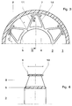
- the line section shown in FIGS. 1 and 2 of a gas-insulated Line 1 has an encapsulation consisting essentially of a tube 2.
- Support insulators 3 are arranged in the interior of the pressure tube, of which only a post insulator 3 is shown, and a substantially parallel to the axis of the Pipe guided and at high voltage potential, tubular trained conductor 4 of a three-phase network or one DC network with line voltages of up to several hundred kV each.
- the casing tube 2 is filled with an insulating gas, such as SF 6 , of up to a few bar pressure and consists of an insulating material, a thermoplastic polymer being used as the material for the insulating material.
- the thermoplastic can be filled with an electrically conductive material, for example with soot, since on the one hand the gas-insulated line 1 is effectively electrostatically shielded from the outside, and on the other hand because the encapsulation tube is assigned a defined potential, in particular earth potential.
- the encapsulation tube 2 is made of easily transportable, for example 10 to 20 m long pipe sections, which are welded together on the front are.
- the material of the encapsulation tube advantageously consists of a uncrosslinked thermoplastic. Then it works well at elevated temperatures deform and weld well.
- a suitable thermoplastic material is for example a non-crosslinked high density polyethylene.
- On the outer surface of the encapsulation tube 2 is also a potential control, not designated Layer, preferably made of conductive or semiconductive material. This layer assigns 2 ground potential to the outer surface of the encapsulation tube.
- the post insulators each contain one corresponding to the post insulator 3 of the outer surface of the current conductor 4 fixed support ring 5.
- the support ring 5 has on its inner surface facing the outer surface of the current conductor 4 at least one by contacting the outer surface of the current conductor 4 its potential, preferably ring-shaped, electrode 6, which the current conductor 4, support insulator 3 and insulating gas common triple points dielectric relieved.
- the support ring 5 On the support ring 5 are three evenly distributed in the circumferential direction and formed hollow support elements, each of which is transverse to the axis have an arc-shaped profile.
- the support elements point two each offset in the circumferential direction against each other on the support ring 5 and initially predominantly radially guided legs 11 and 12, which are integrated in the opposite direction into a foot 7.
- the foot 7 is in generally on the inner surface of the encapsulation tube 2, but can also by a gap not apparent from the figure. At least two the feet rest on the inner surface of the encapsulation tube 2.
- Each of the feet 7 has compared to the distance a between the conductor 4 and the inner surface of the Encapsulation tube 2 small thickness d, is bowl-shaped and has one length l in the axial direction compared to the thickness d.
- the post insulator 3 is a high mechanical stability of the Head section reached because the feet 7 with a large area on the Can rest on the inner surface of the encapsulation tube 2 and thus a large one Apply clamping force with a relatively low surface pressure.
- the end relatively easily deformable material existing encapsulation tube 2 so its geometric dimensions when operating the line section largely preserved. Deformations or breakage of the post insulator 3 to avoid, it is appropriate to the support ring 5 and the feet 7 from one thermoplastic and highly resilient thermoplastic polymer, advantageously to form a polysulfone.
- the support insulator 3 By designing the support insulator 3 with thin cup-shaped feet 7 it is also achieved that relatively little insulation material with a compared to the insulating gas large dielectric constant on the inner surface of the Encapsulation tube 2 is guided. In contrast to post insulators according to the state the technology, which have edges or tips resting on the wall or with a large amount of material on the inner surface of the encapsulation tube are guided, so the electric field strength in the between post insulator and The inner surface of the encapsulation tube is kept small and the Dielectric strength of the conductor section optimized according to the invention.
- the feet can be designed essentially in the manner of an ellipse, they can also be circular or parabolic.
- the post insulator 3 is mirror-symmetrical to a perpendicular to the tube axis level 8 formed. He can then go through in a simple manner Injection molding can be made. It is advantageous here for the electrode 6 to form an electrically conductive plastic, since then the electrode 6 also can be produced by injection molding.
- the feet each have two in the direction of End portions 9, 10 spaced from each other on the tube axis, each of which in the manner of a sled runner opposite the inner surface of the encapsulation tube 2 are bent and according to the embodiment of Figures 1 and 2 facilitate the insertion of the support insulator 3 into the encapsulation tube and Reduce unwanted material abrasion.
- the diameter of the encapsulation tube 2 is therefore larger than the diameter of the Post insulator 3.
- the post insulator 3 can therefore be practically free of forces and free of any abrasion can be pushed into the encapsulation tube.
- the support insulator 3 By designing the support insulator 3 with thin cup-shaped feet 7 it is achieved that relatively little insulating material with a compared to the Isoliergas large dielectric constant on the inner surface of the Encapsulation tube 2 is guided. It becomes the electric field strength in the more between the support insulator and the inner surface of the encapsulation tube or less large columns kept low and the dielectric strength of the Conductor section optimized according to the invention.
Landscapes
- Insulators (AREA)
- Rigid Pipes And Flexible Pipes (AREA)
Applications Claiming Priority (2)
| Application Number | Priority Date | Filing Date | Title |
|---|---|---|---|
| DE19821888 | 1998-05-15 | ||
| DE19821888A DE19821888A1 (de) | 1998-05-15 | 1998-05-15 | Leitungsabschnitt einer gasisolierten Leitung |
Publications (1)
| Publication Number | Publication Date |
|---|---|
| EP0957554A1 true EP0957554A1 (fr) | 1999-11-17 |
Family
ID=7867922
Family Applications (1)
| Application Number | Title | Priority Date | Filing Date |
|---|---|---|---|
| EP99810425A Withdrawn EP0957554A1 (fr) | 1998-05-15 | 1999-05-14 | Section d une ligne isolée par gaz |
Country Status (3)
| Country | Link |
|---|---|
| US (1) | US6198039B1 (fr) |
| EP (1) | EP0957554A1 (fr) |
| DE (1) | DE19821888A1 (fr) |
Families Citing this family (5)
| Publication number | Priority date | Publication date | Assignee | Title |
|---|---|---|---|---|
| DE10128842A1 (de) * | 2001-06-15 | 2002-12-19 | Abb Technology Ag Zuerich | Isolator für eine gasisolierte Leitung |
| WO2004061872A1 (fr) * | 2002-12-20 | 2004-07-22 | Siemens Aktiengesellschaft | Isolateur support en forme de colonne |
| DE102011003683A1 (de) | 2011-02-07 | 2012-08-09 | Siemens Aktiengesellschaft | Isolatoranordnung |
| CN111145969B (zh) * | 2018-11-05 | 2021-08-06 | 平高集团有限公司 | Gil的三支柱绝缘子 |
| CN113392550A (zh) * | 2021-06-10 | 2021-09-14 | 南方电网科学研究院有限责任公司 | 三支柱绝缘子柱腿结构协同设计方法、系统、介质及终端 |
Citations (2)
| Publication number | Priority date | Publication date | Assignee | Title |
|---|---|---|---|---|
| US4132855A (en) * | 1977-02-14 | 1979-01-02 | Gould Inc. | Support insulator for gas-filled high-voltage transmission line |
| EP0789438A2 (fr) * | 1996-02-08 | 1997-08-13 | Asea Brown Boveri Ag | Section de conduit à isolation par gaz |
Family Cites Families (8)
| Publication number | Priority date | Publication date | Assignee | Title |
|---|---|---|---|---|
| GB1073606A (en) * | 1965-01-11 | 1967-06-28 | Central Electr Generat Board | Improvements in or relating to electric cables with compressed gas insulation |
| US4160119A (en) * | 1971-07-13 | 1979-07-03 | Kabel-Und Metallwerke Gutehoffnungshuette Ag | High voltage electrical cables |
| DE2236854C2 (de) * | 1972-07-27 | 1983-12-29 | kabelmetal electro GmbH, 3000 Hannover | Abstandshalter für gasisolierte Hochspannungskabel |
| DE2347927C3 (de) * | 1973-09-24 | 1981-07-16 | Siemens AG, 1000 Berlin und 8000 München | Ringförmige Steuerelektrode für einen im wesentlichen trichterförmigen Stützisolator einer gekapselten, gasisolierten Hochspannungsrohrleitung |
| US3864507A (en) * | 1974-02-25 | 1975-02-04 | Aluminum Co Of America | Electrical conductor |
| US4018978A (en) * | 1976-02-25 | 1977-04-19 | I-T-E Imperial Corporation | Orbital disc insulator for SF6 gas-insulated bus |
| US4415763A (en) * | 1980-11-14 | 1983-11-15 | Westinghouse Electric Corp. | Gas-insulated transmission line having improved outer enclosure |
| FR2714203B1 (fr) * | 1993-12-21 | 1996-01-19 | Gec Alsthom T & D Sa | Ligne à haute tension à isolation gazeuse pour longue distance. |
-
1998
- 1998-05-15 DE DE19821888A patent/DE19821888A1/de not_active Withdrawn
-
1999
- 1999-05-14 EP EP99810425A patent/EP0957554A1/fr not_active Withdrawn
- 1999-05-14 US US09/311,645 patent/US6198039B1/en not_active Expired - Fee Related
Patent Citations (2)
| Publication number | Priority date | Publication date | Assignee | Title |
|---|---|---|---|---|
| US4132855A (en) * | 1977-02-14 | 1979-01-02 | Gould Inc. | Support insulator for gas-filled high-voltage transmission line |
| EP0789438A2 (fr) * | 1996-02-08 | 1997-08-13 | Asea Brown Boveri Ag | Section de conduit à isolation par gaz |
Also Published As
| Publication number | Publication date |
|---|---|
| US6198039B1 (en) | 2001-03-06 |
| DE19821888A1 (de) | 1999-11-18 |
Similar Documents
| Publication | Publication Date | Title |
|---|---|---|
| DE3145896C2 (de) | Kunststoffisolator | |
| DE2937253C2 (fr) | ||
| DE69304185T2 (de) | Überspannungsableiter auf Varistor-Basis, insbesondere für hohe Spannungen | |
| DE69505165T2 (de) | Elektrischer Kabelendverschluss | |
| EP0075668A2 (fr) | Disjoncteur à gaz comprimé | |
| DE4426927A1 (de) | Elektrischer Isolator aus Silikongummi für Hochspannungsanwendungen | |
| EP0789438A2 (fr) | Section de conduit à isolation par gaz | |
| EP0957554A1 (fr) | Section d une ligne isolée par gaz | |
| CH635461A5 (de) | Starkstromschalter mit sprengausloesung. | |
| EP0457081B2 (fr) | Isolateur | |
| DE2652609A1 (de) | Vorrichtung und verfahren zum einfangen von partikeln in einer geschlossenen elektrischen hochspannungs-sammelschienenvorrichtung | |
| EP0789437A2 (fr) | Section de conduit à isolation par gaz | |
| DE19603215A1 (de) | Sammelschienensystem | |
| EP0774816A2 (fr) | Conduit à isolation par gaz | |
| EP0164023A2 (fr) | Assemblage pour connecter deux conducteurs | |
| EP0789424A2 (fr) | Elément de raccord pour deux sections de conducteur à haute tension | |
| DE2849560C2 (de) | Gekapselte, druckgasisolierte Hochspannungsleitung | |
| DE3146238C2 (fr) | ||
| DE1640699A1 (de) | Endenabschluss fuer Hochspannungskabel und -leitungen | |
| DE19842726A1 (de) | Leitungsabschnitt einer gasisolierten Leitung und Verfahren zur Herstellung dieses Leitungsabschnitts | |
| CH694413A5 (de) | Isolator für eine Hochspannungsschaltanlage. | |
| DE19756355A1 (de) | Leitungsabschnitt einer gasisolierten Leitung | |
| DE19604482A1 (de) | Unterirdisch verlegbare gasisolierte Leitung | |
| EP0087605B1 (fr) | Connexion coaxiale pour deux fils conducteurs | |
| DE2154616A1 (de) | Isolator fur elektrische Oberleitungs Fahrdrahtanl agen |
Legal Events
| Date | Code | Title | Description |
|---|---|---|---|
| PUAI | Public reference made under article 153(3) epc to a published international application that has entered the european phase |
Free format text: ORIGINAL CODE: 0009012 |
|
| AK | Designated contracting states |
Kind code of ref document: A1 Designated state(s): BE CH DE FR GB IT LI NL |
|
| AX | Request for extension of the european patent |
Free format text: AL;LT;LV;MK;RO;SI |
|
| 17P | Request for examination filed |
Effective date: 20000318 |
|
| RAP1 | Party data changed (applicant data changed or rights of an application transferred) |
Owner name: ABB HOCHSPANNUNGSTECHNIK AG |
|
| AKX | Designation fees paid |
Free format text: BE CH DE FR GB IT LI NL |
|
| STAA | Information on the status of an ep patent application or granted ep patent |
Free format text: STATUS: THE APPLICATION HAS BEEN WITHDRAWN |
|
| RAP1 | Party data changed (applicant data changed or rights of an application transferred) |
Owner name: ABB SCHWEIZ AG |
|
| 18W | Application withdrawn |
Withdrawal date: 20020322 |