EP0958059B1 - Installation de pre-broyage - Google Patents
Installation de pre-broyage Download PDFInfo
- Publication number
- EP0958059B1 EP0958059B1 EP97937648A EP97937648A EP0958059B1 EP 0958059 B1 EP0958059 B1 EP 0958059B1 EP 97937648 A EP97937648 A EP 97937648A EP 97937648 A EP97937648 A EP 97937648A EP 0958059 B1 EP0958059 B1 EP 0958059B1
- Authority
- EP
- European Patent Office
- Prior art keywords
- shaft
- motor
- plant
- speed
- driving
- Prior art date
- Legal status (The legal status is an assumption and is not a legal conclusion. Google has not performed a legal analysis and makes no representation as to the accuracy of the status listed.)
- Expired - Lifetime
Links
- 230000004044 response Effects 0.000 claims abstract description 3
- 230000009467 reduction Effects 0.000 claims description 7
- 230000004907 flux Effects 0.000 claims description 6
- 238000012544 monitoring process Methods 0.000 claims 2
- 238000009434 installation Methods 0.000 description 22
- 239000000463 material Substances 0.000 description 9
- 230000005284 excitation Effects 0.000 description 5
- 238000004880 explosion Methods 0.000 description 4
- 239000003638 chemical reducing agent Substances 0.000 description 3
- 230000009471 action Effects 0.000 description 1
- 230000033228 biological regulation Effects 0.000 description 1
- 230000015556 catabolic process Effects 0.000 description 1
- 230000007423 decrease Effects 0.000 description 1
- 230000003247 decreasing effect Effects 0.000 description 1
- 238000010586 diagram Methods 0.000 description 1
- 239000000446 fuel Substances 0.000 description 1
- 239000002184 metal Substances 0.000 description 1
- 238000011084 recovery Methods 0.000 description 1
- 238000004064 recycling Methods 0.000 description 1
Images

Classifications
-
- B—PERFORMING OPERATIONS; TRANSPORTING
- B02—CRUSHING, PULVERISING, OR DISINTEGRATING; PREPARATORY TREATMENT OF GRAIN FOR MILLING
- B02C—CRUSHING, PULVERISING, OR DISINTEGRATING IN GENERAL; MILLING GRAIN
- B02C18/00—Disintegrating by knives or other cutting or tearing members which chop material into fragments
- B02C18/06—Disintegrating by knives or other cutting or tearing members which chop material into fragments with rotating knives
- B02C18/16—Details
- B02C18/22—Feed or discharge means
- B02C18/2225—Feed means
- B02C18/2233—Feed means of ram or pusher type
-
- B—PERFORMING OPERATIONS; TRANSPORTING
- B02—CRUSHING, PULVERISING, OR DISINTEGRATING; PREPARATORY TREATMENT OF GRAIN FOR MILLING
- B02C—CRUSHING, PULVERISING, OR DISINTEGRATING IN GENERAL; MILLING GRAIN
- B02C18/00—Disintegrating by knives or other cutting or tearing members which chop material into fragments
- B02C18/06—Disintegrating by knives or other cutting or tearing members which chop material into fragments with rotating knives
- B02C18/14—Disintegrating by knives or other cutting or tearing members which chop material into fragments with rotating knives within horizontal containers
- B02C18/142—Disintegrating by knives or other cutting or tearing members which chop material into fragments with rotating knives within horizontal containers with two or more inter-engaging rotatable cutter assemblies
-
- B—PERFORMING OPERATIONS; TRANSPORTING
- B02—CRUSHING, PULVERISING, OR DISINTEGRATING; PREPARATORY TREATMENT OF GRAIN FOR MILLING
- B02C—CRUSHING, PULVERISING, OR DISINTEGRATING IN GENERAL; MILLING GRAIN
- B02C18/00—Disintegrating by knives or other cutting or tearing members which chop material into fragments
- B02C18/06—Disintegrating by knives or other cutting or tearing members which chop material into fragments with rotating knives
- B02C18/16—Details
- B02C18/24—Drives
-
- H—ELECTRICITY
- H02—GENERATION; CONVERSION OR DISTRIBUTION OF ELECTRIC POWER
- H02P—CONTROL OR REGULATION OF ELECTRIC MOTORS, ELECTRIC GENERATORS OR DYNAMO-ELECTRIC CONVERTERS; CONTROLLING TRANSFORMERS, REACTORS OR CHOKE COILS
- H02P5/00—Arrangements specially adapted for regulating or controlling the speed or torque of two or more electric motors
- H02P5/68—Arrangements specially adapted for regulating or controlling the speed or torque of two or more electric motors controlling two or more DC dynamo-electric motors
Definitions
- the subject of the present invention is a pre-grinding installation objects and in particular, but not exclusively, vehicle wrecks automobiles or other types of wrecks.
- the operation of a grinding unit is subject to various risks such as explosions, fires, machine breakdowns, etc. incidents are mainly caused by the introduction into the shredder, among wrecks, hollow bodies such as tanks, bottles of gas, tanks containing G.P.L or massive parts.
- pre-shredders The principle of pre-shredders is to pass between two shafts fitted with shredding hooks and rotating at high speeds different materials to be pre-shredded.
- FIG. 1 attached schematically illustrates such a pre-crusher known type.
- Inside an enclosure 10 there are two trees horizontal parallel to each other 12 and 14 which are provided on their peripheries of shredding hooks such as 16.
- There is a tree lower 14 essentially used to train objects or products to pre-grind and an upper shaft 12 which, in combination with the rotation of the shaft 14, effectively makes it possible to obtain the pre-grinding, the two shafts turning in opposite directions and having different speeds.
- the materials or objects to be pre-shredded are brought using a platform 18 mounted at the end of a jack 20, the platform being pivotally mounted relative to the jack 20 around the axis 22.
- the drive in shafts 12 and 14 are rotated using a single hydraulic motor which is controlled by a hydraulic power plant.
- the hydraulic motor drives one of the two shafts, a gear system allowing training the other tree.
- These training systems involve great rigidity in the operation of the pre-crusher by imposing a constant speed ratio between the two shafts.
- pre-grinding machines currently in operation allow the best processing 45 tonnes of material per hour.
- An object of the present invention is to provide an installation for pre-grinding which allows greater efficiency, increased safety and better adaptability to the nature of materials to be pre-ground.
- control device includes means for continuously controlling the operation of the installation and adapt the parameters of operating under conditions of use, which improves the efficiency of installation and increases security.
- each of the two motors is a direct current motor preferably of the full excitation type flux.
- FIG. 2 there is shown a top view of the box 30 of the pre-grinding installation in which the two shafts are mounted with their shredding fangs.
- the output of the first shaft 32 or shredding shaft which is coupled to a reduction gear mechanical 34 constituting at the same time, in the embodiment considered, a bevel gear.
- the input 34a of the reducer 34 is coupled mechanically to a first motor 36.
- the first motor 36 is an electric motor which will be explained later characteristics.
- the outlet 38 of the second tree or drive shaft which is coupled to a second reducer 40.
- the input 40a of the reducer 40 is coupled to a second motor 42 independent of the first motor 36.
- the second motor 42 is also an electric motor.
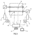
- each motor 36 and 42 is associated with an electrical circuit or separate control electronics referenced 44 and 46 respectively, each control circuit comprises in particular a dimmer voltage. These circuits 44 and 46 receive on their respective inputs control signals emitted by a control or piloting circuit the entire pre-grinding installation.
- This driving circuit is referenced 48 in Figure 3.
- sensors such as 50 and 52 which convert electrical signals into information in particular of torque and speed of rotation of each of the shafts 32 and 38.
- the outputs of sensors 50 and 52 are connected to inputs a) and b) of the control circuit 48.
- the control circuit 48 can also receive on its entry c) piloting instructions from the installation entries using the keyboard 49 which are in particular relating to the load which will be entered in the pre-crusher as well as the nature of materials to be pre-ground. Also preferably, the control circuit 48 is associated with display panels 54 which allow the manager of the installation to continuously monitor the operation of the installation pre-grinding and detect any operational problems.
- the drive motors 36 and 42 are DC motors with full flux excitation.
- armature voltage represents the speed of rotation of the shaft associated with the motor and the current induces the torque.
- the current of the variator used to control the motor is limited to 370 amps which allows to obtain a torque of 450,000 Nm.
- the speed maximum rotation of the driven shaft can only be 2.7 turns per minute for constant torque operation.
- we use the principle of flux reduction which consists in decreasing the excitation voltage which increases the speed but at the same time decreases the torque.
- control circuit has, among other functions, when the set speed is less than 2.7 rpm, order the dimmer to keep the motor in full flow excitation and reduce the flow proportional to the speed beyond 2.7 rpm up to 4 revolutions per minute.
- the drive associated with this motor is limited to 1,400 amps which provides a torque of 415,000 Nm.
- the maximum speed can only be 12 revolutions per minute for constant torque operation. If we want to get a speed greater than 12 rpm and keep the same power, we use, as we have already explained, flow reduction. So, as long as the speed programmed in circuit 48 is less than 12 revolutions per minute, the action of the control circuit combined with the variator consists in keeping the motor in full flow excitation. On the other hand, when the speed must be between 12 and 17 revolutions per minute, the speed controller of the command is used to proportionally reduce the flow.
- the control circuit 48 not only serves to transmit to the circuit of control, including associated variators, of each motor operating parameters as a function of speed and torque desired but also to control the synchronism of the operation of the two motors, that is to say of the two shafts. Indeed, the fast tree does not must in no case have a speed close to that of the slow shaft since in this case there would be no shredding result. Consequently, the control circuit 48 checks that the speed of the fast shaft does not pass below a value that can be set by three times the slow speed. If the speed of the fast shaft drops below three times the speed of the slow shaft, circuit 48 will send a signal to the control circuit of the motor associated with the slow shaft to modify the speed setpoint of this tree.
- control circuit 48 all of the functions implemented by the control circuit 48 are implemented by computer means for example using a microprocessor that runs different programs corresponding to the different control and control.
Landscapes
- Engineering & Computer Science (AREA)
- Food Science & Technology (AREA)
- Power Engineering (AREA)
- Crushing And Pulverization Processes (AREA)
- Disintegrating Or Milling (AREA)
- Polishing Bodies And Polishing Tools (AREA)
- Crushing And Grinding (AREA)
- Organic Low-Molecular-Weight Compounds And Preparation Thereof (AREA)
- Transition And Organic Metals Composition Catalysts For Addition Polymerization (AREA)
- Fire-Detection Mechanisms (AREA)
- Burglar Alarm Systems (AREA)
- Fertilizers (AREA)
- Saccharide Compounds (AREA)
- Agricultural Chemicals And Associated Chemicals (AREA)
Description
- un premier moteur couplé au premier arbre par un premier ensemble réducteur et des premiers moyens de commande dudit premier moteur,
- un deuxième moteur distinct du premier couplé au deuxième arbre par un deuxième ensemble réducteur et des deuxièmes moyens de commande dudit deuxième moteur distincts des premiers moyens de commande, et
- des moyens de contrôle de l'installation comprenant des moyens pour recevoir des instructions de pilotage de l'installation, des moyens capteurs pour délivrer des informations représentatives du fonctionnement effectif de l'installation, et des moyens pour transmettre à chaque moyen de commande de moteur des instructions de commande en réponse aux instructions de pilotage et aux informations délivrées par lesdits capteurs.
- la figure 1 déjà décrite représente le principe d'une installation de pré-broyage;
- la figure 2 est une vue de dessus d'une installation de pré-broyage conforme à l'invention; et
- la figure 3 est une vue schématique montrant l'ensemble des moyens de régulation et de commande.
Claims (4)
- Installation de pré-broyage d'objets comprenant un premier arbre d'entraínement des objets et un deuxième arbre de déchiquetage des objets entraínés, les deux arbres étant munis de crocs de déchiquetage et des moyens moteur d'entraínement en rotation des deux arbres, caractérisée en ce que les moyens moteur d'entraínement en rotation comprennent :un premier moteur à courant continu couplé au premier arbre par un premier ensemble réducteur pour entraíner ledit premier arbre à une première vitesse de rotation et des premiers moyens de commande dudit moteur;un deuxième moteur à courant continu distinct du premier couplé au deuxième arbre par un deuxième ensemble réducteur pour entraíner le deuxième arbre à une deuxième vitesse supérieure à la première vitesse, et des deuxièmes moyens de commande dudit deuxième moteur, distincts des premiers moyens de commande, et des moyens de contrôle de l'installation comprenant des moyens pour recevoir des instructions de pilotage de l'installation, des moyens capteurs pour délivrer des informations représentatives de la vitesse de rotation et du couple de chacun des arbres, et du fonctionnement effectif de l'installation et des moyens pour transmettre à chaque moyen de commande des moteurs des instructions de commande en réponse aux instructions de pilotage et aux informations délivrées par lesdits capteurs.
- Installation de pré-broyage selon la revendication 1, caractérisée en ce que les moteurs électriques sont des moteurs à courant continu avec excitation plein flux.
- Installation selon la revendication 2, caractérisée en ce que chacun desdits moyens de commande comprend un variateur de flux apte à faire varier le flux du moteur qu'il commande.
- Installation selon l'une quelconque des revendications 1 à 3, caractérisée en ce que les moyens de contrôle de l'installation comprennent des moyens pour contrôler que la vitesse dudit premier arbre est de l'ordre du tiers de la vitesse dudit deuxième arbre et des moyens pour modifier la vitesse dudit premier arbre si la vitesse dudit deuxième arbre devient inférieure à trois fois celle du premier arbre.
Applications Claiming Priority (3)
| Application Number | Priority Date | Filing Date | Title |
|---|---|---|---|
| FR9610355A FR2752535B1 (fr) | 1996-08-21 | 1996-08-21 | Installation de pre-broyage |
| FR9610355 | 1996-08-21 | ||
| PCT/FR1997/001512 WO1998007519A1 (fr) | 1996-08-21 | 1997-08-21 | Installation de pre-broyage |
Publications (2)
| Publication Number | Publication Date |
|---|---|
| EP0958059A1 EP0958059A1 (fr) | 1999-11-24 |
| EP0958059B1 true EP0958059B1 (fr) | 2003-03-19 |
Family
ID=9495157
Family Applications (1)
| Application Number | Title | Priority Date | Filing Date |
|---|---|---|---|
| EP97937648A Expired - Lifetime EP0958059B1 (fr) | 1996-08-21 | 1997-08-21 | Installation de pre-broyage |
Country Status (8)
| Country | Link |
|---|---|
| EP (1) | EP0958059B1 (fr) |
| AT (1) | ATE234683T1 (fr) |
| AU (1) | AU4019897A (fr) |
| DE (1) | DE69720059T2 (fr) |
| ES (1) | ES2195164T3 (fr) |
| FR (1) | FR2752535B1 (fr) |
| PT (1) | PT958059E (fr) |
| WO (1) | WO1998007519A1 (fr) |
Cited By (1)
| Publication number | Priority date | Publication date | Assignee | Title |
|---|---|---|---|---|
| ITUD20100016A1 (it) * | 2010-01-29 | 2011-07-30 | C & G Costruzioni Meccaniche S R L | Dispositivo di premacinazione e relativo procedimento |
Families Citing this family (1)
| Publication number | Priority date | Publication date | Assignee | Title |
|---|---|---|---|---|
| FR2832939B1 (fr) | 2001-12-05 | 2004-02-27 | Cff Recycling | Installation amelioree de pre-broyage d'objets |
Family Cites Families (4)
| Publication number | Priority date | Publication date | Assignee | Title |
|---|---|---|---|---|
| GB1569375A (en) * | 1978-04-21 | 1980-06-11 | Dresser Europe Sa | Shredding machine |
| FR2573327B1 (fr) * | 1984-11-16 | 1988-05-06 | Isme Sa | Dechiqueteur comportant deux arbres rotatifs a axes horizontaux |
| JPH0622440Y2 (ja) * | 1988-05-13 | 1994-06-15 | 手塚興産株式会社 | 破砕機 |
| US5427321A (en) * | 1992-07-03 | 1995-06-27 | Meiden Plant Engineering & Construction Co., Ltd. | Waste paper processing system |
-
1996
- 1996-08-21 FR FR9610355A patent/FR2752535B1/fr not_active Expired - Fee Related
-
1997
- 1997-08-21 ES ES97937648T patent/ES2195164T3/es not_active Expired - Lifetime
- 1997-08-21 EP EP97937648A patent/EP0958059B1/fr not_active Expired - Lifetime
- 1997-08-21 PT PT97937648T patent/PT958059E/pt unknown
- 1997-08-21 AU AU40198/97A patent/AU4019897A/en not_active Abandoned
- 1997-08-21 DE DE69720059T patent/DE69720059T2/de not_active Expired - Lifetime
- 1997-08-21 WO PCT/FR1997/001512 patent/WO1998007519A1/fr not_active Ceased
- 1997-08-21 AT AT97937648T patent/ATE234683T1/de active
Cited By (2)
| Publication number | Priority date | Publication date | Assignee | Title |
|---|---|---|---|---|
| ITUD20100016A1 (it) * | 2010-01-29 | 2011-07-30 | C & G Costruzioni Meccaniche S R L | Dispositivo di premacinazione e relativo procedimento |
| WO2011092588A1 (fr) | 2010-01-29 | 2011-08-04 | Colombo Giovanni SRL | Dispositif d'écrasement préalable et procédé associé |
Also Published As
| Publication number | Publication date |
|---|---|
| ATE234683T1 (de) | 2003-04-15 |
| AU4019897A (en) | 1998-03-06 |
| FR2752535A1 (fr) | 1998-02-27 |
| DE69720059T2 (de) | 2004-02-19 |
| ES2195164T3 (es) | 2003-12-01 |
| PT958059E (pt) | 2003-08-29 |
| DE69720059D1 (de) | 2003-04-24 |
| FR2752535B1 (fr) | 1998-11-27 |
| EP0958059A1 (fr) | 1999-11-24 |
| WO1998007519A1 (fr) | 1998-02-26 |
Similar Documents
| Publication | Publication Date | Title |
|---|---|---|
| FR2733188A1 (fr) | Equipement d'alimentation electrique installe sous la plate-forme d'un vehicule | |
| CA2785309C (fr) | Aeronef comportant un demarreur-generateur electrique pour le ou chaque turboreacteur et un train d'atterrissage equipe d'un moteur electrique de manoeuvre au sol | |
| EP3122627B1 (fr) | Ensemble de transmission pour aeronef et helicoptere | |
| WO2017081377A1 (fr) | Groupe motopropulseur d'un vehicule | |
| EP0958059B1 (fr) | Installation de pre-broyage | |
| FR2606077A1 (fr) | Systeme differentiel de puissance pour un moteur a turbine a rotors multiples | |
| FR3043362A1 (fr) | Groupe motopropulseur d’un vehicule | |
| FR2689821A1 (fr) | Groupe motopropulseur bi-mode et véhicule équipé d'un tel groupe. | |
| FR2673856A1 (fr) | Destructeur de documents. | |
| EP3176019A1 (fr) | Groupe motopropulseur d'un vehicule | |
| FR2465134A2 (fr) | Transmissions hydrostatiques de puissance a grande place de fonctionnement | |
| FR3043363A1 (fr) | Groupe motopropulseur d’un vehicule | |
| FR2805763A1 (fr) | Broyeur a cone, et dispositif et procede de reglage s'y rapportant | |
| EP1319438B1 (fr) | Installation améliorée de pré-broyage d'objets | |
| FR2640558A1 (fr) | Procede pour l'entrainement hydraulique auxiliaire de roues sur un vehicule | |
| WO2010130941A1 (fr) | Dispositif d'entrainement du rotor d'un broyeur, d'un concasseur ou analogue | |
| EP4041581B1 (fr) | Ensemble de transmission de puissance et véhicule comprenant cet ensemble | |
| FR2972393A1 (fr) | Dispositif de commande d'un vehicule automobile a moteur electrique | |
| FR2950658A1 (fr) | Procede et dispositif de controle d'une partie tournante du corps haute pression d'un moteur d'avion | |
| EP2470303A1 (fr) | Dispositif compact de cisaillage ou dechiquetage et de broyage de produits a broyer | |
| FR2817232A1 (fr) | Ensemble pour orienter un organe de gouverne d'un navire | |
| CA2230270A1 (fr) | Arbre multi motorise | |
| EP1931963A1 (fr) | Dispositif de prelevement de matieres granuleuses ou pulverulentes | |
| US20050209036A1 (en) | Bi-powered clutchless variable speed transmission | |
| FR2677951A1 (fr) | Dispositif d'orientation electrique d'un atterrisseur. |
Legal Events
| Date | Code | Title | Description |
|---|---|---|---|
| PUAI | Public reference made under article 153(3) epc to a published international application that has entered the european phase |
Free format text: ORIGINAL CODE: 0009012 |
|
| 17P | Request for examination filed |
Effective date: 19990217 |
|
| AK | Designated contracting states |
Kind code of ref document: A1 Designated state(s): AT BE CH DE DK ES FI FR GB GR IE IT LI LU MC NL PT SE |
|
| 17Q | First examination report despatched |
Effective date: 20010424 |
|
| GRAH | Despatch of communication of intention to grant a patent |
Free format text: ORIGINAL CODE: EPIDOS IGRA |
|
| GRAH | Despatch of communication of intention to grant a patent |
Free format text: ORIGINAL CODE: EPIDOS IGRA |
|
| GRAA | (expected) grant |
Free format text: ORIGINAL CODE: 0009210 |
|
| AK | Designated contracting states |
Designated state(s): AT BE CH DE DK ES FI FR GB GR IE IT LI LU MC NL PT SE |
|
| PG25 | Lapsed in a contracting state [announced via postgrant information from national office to epo] |
Ref country code: FI Free format text: LAPSE BECAUSE OF FAILURE TO SUBMIT A TRANSLATION OF THE DESCRIPTION OR TO PAY THE FEE WITHIN THE PRESCRIBED TIME-LIMIT Effective date: 20030319 |
|
| REG | Reference to a national code |
Ref country code: GB Ref legal event code: FG4D Free format text: NOT ENGLISH |
|
| REG | Reference to a national code |
Ref country code: CH Ref legal event code: EP |
|
| REG | Reference to a national code |
Ref country code: IE Ref legal event code: FG4D Free format text: FRENCH |
|
| REF | Corresponds to: |
Ref document number: 69720059 Country of ref document: DE Date of ref document: 20030424 Kind code of ref document: P |
|
| PG25 | Lapsed in a contracting state [announced via postgrant information from national office to epo] |
Ref country code: SE Free format text: LAPSE BECAUSE OF FAILURE TO SUBMIT A TRANSLATION OF THE DESCRIPTION OR TO PAY THE FEE WITHIN THE PRESCRIBED TIME-LIMIT Effective date: 20030619 Ref country code: DK Free format text: LAPSE BECAUSE OF FAILURE TO SUBMIT A TRANSLATION OF THE DESCRIPTION OR TO PAY THE FEE WITHIN THE PRESCRIBED TIME-LIMIT Effective date: 20030619 |
|
| REG | Reference to a national code |
Ref country code: GR Ref legal event code: EP Ref document number: 20030402203 Country of ref document: GR |
|
| RAP2 | Party data changed (patent owner data changed or rights of a patent transferred) |
Owner name: CFF RECYCLING |
|
| REG | Reference to a national code |
Ref country code: CH Ref legal event code: PFA Owner name: CFF RECYCLING Free format text: COMPAGNIE FRANCAISE DES FERRAILLES#119 AVENUE DU G?N?RAL MICHEL BIZOT#F-75012 PARIS (FR) -TRANSFER TO- CFF RECYCLING#119 AVENUE DU G?N?RAL MICHEL BIZOT#75012 PARIS (FR) Ref country code: CH Ref legal event code: NV Representative=s name: ARNOLD & SIEDSMA AG |
|
| GBT | Gb: translation of ep patent filed (gb section 77(6)(a)/1977) |
Effective date: 20030717 |
|
| NLT2 | Nl: modifications (of names), taken from the european patent patent bulletin |
Owner name: CFF RECYCLING |
|
| NLT1 | Nl: modifications of names registered in virtue of documents presented to the patent office pursuant to art. 16 a, paragraph 1 |
Owner name: CFF RECYCLING |
|
| PLBE | No opposition filed within time limit |
Free format text: ORIGINAL CODE: 0009261 |
|
| STAA | Information on the status of an ep patent application or granted ep patent |
Free format text: STATUS: NO OPPOSITION FILED WITHIN TIME LIMIT |
|
| 26N | No opposition filed |
Effective date: 20031222 |
|
| REG | Reference to a national code |
Ref country code: CH Ref legal event code: PFA Owner name: CFF RECYCLING Free format text: CFF RECYCLING#119 AVENUE DU GENERAL MICHEL BIZOT#75012 PARIS (FR) -TRANSFER TO- CFF RECYCLING#119 AVENUE DU GENERAL MICHEL BIZOT#75012 PARIS (FR) |
|
| PGFP | Annual fee paid to national office [announced via postgrant information from national office to epo] |
Ref country code: LU Payment date: 20130723 Year of fee payment: 17 |
|
| PGFP | Annual fee paid to national office [announced via postgrant information from national office to epo] |
Ref country code: GR Payment date: 20130729 Year of fee payment: 17 Ref country code: IE Payment date: 20130724 Year of fee payment: 17 Ref country code: CH Payment date: 20130813 Year of fee payment: 17 Ref country code: PT Payment date: 20130221 Year of fee payment: 17 Ref country code: NL Payment date: 20130719 Year of fee payment: 17 Ref country code: DE Payment date: 20130812 Year of fee payment: 17 Ref country code: ES Payment date: 20130828 Year of fee payment: 17 Ref country code: MC Payment date: 20130718 Year of fee payment: 17 Ref country code: AT Payment date: 20130719 Year of fee payment: 17 |
|
| PGFP | Annual fee paid to national office [announced via postgrant information from national office to epo] |
Ref country code: GB Payment date: 20130816 Year of fee payment: 17 Ref country code: FR Payment date: 20130826 Year of fee payment: 17 |
|
| PGFP | Annual fee paid to national office [announced via postgrant information from national office to epo] |
Ref country code: IT Payment date: 20130808 Year of fee payment: 17 |
|
| PGFP | Annual fee paid to national office [announced via postgrant information from national office to epo] |
Ref country code: BE Payment date: 20130830 Year of fee payment: 17 |
|
| REG | Reference to a national code |
Ref country code: PT Ref legal event code: MM4A Free format text: LAPSE DUE TO NON-PAYMENT OF FEES Effective date: 20150223 |
|
| REG | Reference to a national code |
Ref country code: DE Ref legal event code: R119 Ref document number: 69720059 Country of ref document: DE |
|
| REG | Reference to a national code |
Ref country code: NL Ref legal event code: V1 Effective date: 20150301 |
|
| PG25 | Lapsed in a contracting state [announced via postgrant information from national office to epo] |
Ref country code: LU Free format text: LAPSE BECAUSE OF NON-PAYMENT OF DUE FEES Effective date: 20140821 Ref country code: MC Free format text: LAPSE BECAUSE OF NON-PAYMENT OF DUE FEES Effective date: 20140901 |
|
| REG | Reference to a national code |
Ref country code: CH Ref legal event code: PL |
|
| REG | Reference to a national code |
Ref country code: AT Ref legal event code: MM01 Ref document number: 234683 Country of ref document: AT Kind code of ref document: T Effective date: 20140821 |
|
| REG | Reference to a national code |
Ref country code: GR Ref legal event code: ML Ref document number: 20030402203 Country of ref document: GR Effective date: 20150304 |
|
| GBPC | Gb: european patent ceased through non-payment of renewal fee |
Effective date: 20140821 |
|
| PG25 | Lapsed in a contracting state [announced via postgrant information from national office to epo] |
Ref country code: IT Free format text: LAPSE BECAUSE OF NON-PAYMENT OF DUE FEES Effective date: 20140821 Ref country code: PT Free format text: LAPSE BECAUSE OF NON-PAYMENT OF DUE FEES Effective date: 20150223 Ref country code: LI Free format text: LAPSE BECAUSE OF NON-PAYMENT OF DUE FEES Effective date: 20140831 Ref country code: BE Free format text: LAPSE BECAUSE OF NON-PAYMENT OF DUE FEES Effective date: 20140831 Ref country code: CH Free format text: LAPSE BECAUSE OF NON-PAYMENT OF DUE FEES Effective date: 20140831 Ref country code: NL Free format text: LAPSE BECAUSE OF NON-PAYMENT OF DUE FEES Effective date: 20150301 |
|
| REG | Reference to a national code |
Ref country code: IE Ref legal event code: MM4A |
|
| REG | Reference to a national code |
Ref country code: DE Ref legal event code: R119 Ref document number: 69720059 Country of ref document: DE Effective date: 20150303 |
|
| PG25 | Lapsed in a contracting state [announced via postgrant information from national office to epo] |
Ref country code: GR Free format text: LAPSE BECAUSE OF NON-PAYMENT OF DUE FEES Effective date: 20150304 Ref country code: AT Free format text: LAPSE BECAUSE OF NON-PAYMENT OF DUE FEES Effective date: 20140821 |
|
| REG | Reference to a national code |
Ref country code: FR Ref legal event code: ST Effective date: 20150430 |
|
| PG25 | Lapsed in a contracting state [announced via postgrant information from national office to epo] |
Ref country code: GB Free format text: LAPSE BECAUSE OF NON-PAYMENT OF DUE FEES Effective date: 20140821 Ref country code: DE Free format text: LAPSE BECAUSE OF NON-PAYMENT OF DUE FEES Effective date: 20150303 |
|
| PG25 | Lapsed in a contracting state [announced via postgrant information from national office to epo] |
Ref country code: IE Free format text: LAPSE BECAUSE OF NON-PAYMENT OF DUE FEES Effective date: 20140821 Ref country code: FR Free format text: LAPSE BECAUSE OF NON-PAYMENT OF DUE FEES Effective date: 20140901 |
|
| REG | Reference to a national code |
Ref country code: ES Ref legal event code: FD2A Effective date: 20150925 |
|
| PG25 | Lapsed in a contracting state [announced via postgrant information from national office to epo] |
Ref country code: ES Free format text: LAPSE BECAUSE OF NON-PAYMENT OF DUE FEES Effective date: 20140822 |