EP0958085B1 - Plaquette de coupe et outil de fraisage - Google Patents
Plaquette de coupe et outil de fraisage Download PDFInfo
- Publication number
- EP0958085B1 EP0958085B1 EP98909329A EP98909329A EP0958085B1 EP 0958085 B1 EP0958085 B1 EP 0958085B1 EP 98909329 A EP98909329 A EP 98909329A EP 98909329 A EP98909329 A EP 98909329A EP 0958085 B1 EP0958085 B1 EP 0958085B1
- Authority
- EP
- European Patent Office
- Prior art keywords
- cutting
- faces
- edges
- longitudinal
- cutting edges
- Prior art date
- Legal status (The legal status is an assumption and is not a legal conclusion. Google has not performed a legal analysis and makes no representation as to the accuracy of the status listed.)
- Expired - Lifetime
Links
Images



Classifications
-
- B—PERFORMING OPERATIONS; TRANSPORTING
- B23—MACHINE TOOLS; METAL-WORKING NOT OTHERWISE PROVIDED FOR
- B23C—MILLING
- B23C5/00—Milling-cutters
- B23C5/16—Milling-cutters characterised by physical features other than shape
- B23C5/20—Milling-cutters characterised by physical features other than shape with removable cutter bits or teeth or cutting inserts
- B23C5/202—Plate-like cutting inserts with special form
-
- B—PERFORMING OPERATIONS; TRANSPORTING
- B23—MACHINE TOOLS; METAL-WORKING NOT OTHERWISE PROVIDED FOR
- B23B—TURNING; BORING
- B23B2200/00—Details of cutting inserts
- B23B2200/36—Other features of cutting inserts not covered by B23B2200/04 - B23B2200/32
- B23B2200/369—Mounted tangentially, i.e. where the rake face is not the face with the largest area
-
- B—PERFORMING OPERATIONS; TRANSPORTING
- B23—MACHINE TOOLS; METAL-WORKING NOT OTHERWISE PROVIDED FOR
- B23C—MILLING
- B23C2200/00—Details of milling cutting inserts
- B23C2200/12—Side or flank surfaces
- B23C2200/125—Side or flank surfaces discontinuous
-
- B—PERFORMING OPERATIONS; TRANSPORTING
- B23—MACHINE TOOLS; METAL-WORKING NOT OTHERWISE PROVIDED FOR
- B23C—MILLING
- B23C2200/00—Details of milling cutting inserts
- B23C2200/36—Other features of the milling insert not covered by B23C2200/04 - B23C2200/32
- B23C2200/367—Mounted tangentially, i.e. where the rake face is not the face with largest area
-
- Y—GENERAL TAGGING OF NEW TECHNOLOGICAL DEVELOPMENTS; GENERAL TAGGING OF CROSS-SECTIONAL TECHNOLOGIES SPANNING OVER SEVERAL SECTIONS OF THE IPC; TECHNICAL SUBJECTS COVERED BY FORMER USPC CROSS-REFERENCE ART COLLECTIONS [XRACs] AND DIGESTS
- Y10—TECHNICAL SUBJECTS COVERED BY FORMER USPC
- Y10T—TECHNICAL SUBJECTS COVERED BY FORMER US CLASSIFICATION
- Y10T407/00—Cutters, for shaping
- Y10T407/23—Cutters, for shaping including tool having plural alternatively usable cutting edges
-
- Y—GENERAL TAGGING OF NEW TECHNOLOGICAL DEVELOPMENTS; GENERAL TAGGING OF CROSS-SECTIONAL TECHNOLOGIES SPANNING OVER SEVERAL SECTIONS OF THE IPC; TECHNICAL SUBJECTS COVERED BY FORMER USPC CROSS-REFERENCE ART COLLECTIONS [XRACs] AND DIGESTS
- Y10—TECHNICAL SUBJECTS COVERED BY FORMER USPC
- Y10T—TECHNICAL SUBJECTS COVERED BY FORMER US CLASSIFICATION
- Y10T407/00—Cutters, for shaping
- Y10T407/23—Cutters, for shaping including tool having plural alternatively usable cutting edges
- Y10T407/235—Cutters, for shaping including tool having plural alternatively usable cutting edges with integral chip breaker, guide or deflector
-
- Y—GENERAL TAGGING OF NEW TECHNOLOGICAL DEVELOPMENTS; GENERAL TAGGING OF CROSS-SECTIONAL TECHNOLOGIES SPANNING OVER SEVERAL SECTIONS OF THE IPC; TECHNICAL SUBJECTS COVERED BY FORMER USPC CROSS-REFERENCE ART COLLECTIONS [XRACs] AND DIGESTS
- Y10—TECHNICAL SUBJECTS COVERED BY FORMER USPC
- Y10T—TECHNICAL SUBJECTS COVERED BY FORMER US CLASSIFICATION
- Y10T407/00—Cutters, for shaping
- Y10T407/24—Cutters, for shaping with chip breaker, guide or deflector
Definitions
- the invention relates to a cutting insert with a essential cubic body, which is used as an indexable insert is equipped with eight usable cutting edges, with two arranged parallel to each other, flat and from a mounting hole penetrated larger areas and four on it adjacent side faces, namely two parallel small end faces and larger ones lying opposite one another Longitudinal surfaces, each centered along their long axis a protruding and as a contact surface when clamping the Have cutting insert in a tool carrier web, the larger areas have a rounded edge in passed the small end faces, so that on the long side approximately quarter-circular cutting edges as a boundary line to the end faces in the corner area, the long ones Cutting edges as boundary lines between the larger areas and the adjacent longitudinal surface is curved in an arc shape, so that there is a mirror symmetry to the longitudinal center plane and the transverse center plane Body results.
- Such a cutting insert is for example from the DE 295 16 668 U1 known.
- This cutting insert has four long cutting edges, which have a convex curved cut contour.
- the longitudinal surfaces are cut through on the short end sides short straight cutting edges to the respective end faces limited to that of each running in a quarter circle Merging the cutting edge corners into the long cutting edges.
- cutting edges have positive wedge angles, are on the long sides following the long cutting edges Chip troughs molded in, are equally in the area of quarter-circular cutting edge troughs arranged.
- cutting inserts are said to be on a milling cutter head be arranged evenly distributed on the circumference, the Cutting inserts both on the peripheral surface and on the end face of the tool holder are mounted such that the cutting edges of all in the active position Can cut cutting inserts in the radial or axial direction, however, in the radial direction over the in each case Cutting edges in the active position on the face the cutting inserts slightly protrude from the tool holder, while those in the active position Cutting edges of those located on the end face of the tool carrier Cutting inserts in the axial direction over each in The cutting edges on the circumferential circumferential surface are in the active position of the cutting inserts located on the tool holder.
- the installation position must be radial and axially so that the eight cutting edges can be used.
- the first plate must be moved from the next one certain amount will be offset, so that the to be hired Clearance angle does not damage the milling contour due to the above Plates done.
- the indexable insert is not suitable.
- Corresponding also applies to the essentially identical Cutting insert according to US-A-3 762 005.
- the long cutting edges also form here their respective end and the rounded edge between the small end surface and the larger surface an angle ⁇ 90 °.
- the long cutting edge has a concave one A constriction in the course or in the middle of the cutting edge.
- a cutting insert is known from DE 83 17 114.2 U1, which is essentially rectangular in plan view and the long side of the rake in the middle one have a certain constriction, but they are Side edges not designed for machining or none Cutting edges.
- the average set back against the cutting edge ends on both sides Part when cutting with one or the other Cutting edge end, so "twice” can be used if the Main wear occurring in the area of the cutting corner lies.
- the cutting insert according to the invention which is on a milling cutter is attached tangentially, which often allows at the Larger crankshaft machining in the pin bearing area Cover the measurements of the cheeks so that a depth of cut greater than 0.5 x insert length is possible because of how already mentioned, both the left and right cutting edge halves can be used as a full-fledged cutting edge and Middle of both, both left and right Cutting edge can be used.
- the long ones Cutting edges can be at least partially concave or they are made up of each other at an angle> 180 ° the bordering straight sections together. Is essential it that the basically concave shape of the long Cutting edge with a constriction, i.e. a reset Center area, is retained.
- the middle area the long cutting edge is linear, preferably over a length up to 1/2 of the total cutting edge length.
- the side rake angle lies between the long cutting edge and the rounded one Edge between 0 ° and 20 °; the rake angle between the larger area and the long side is positive, preferably it is between 0 ° and 20 °.
- the concave shape of the long cutting edge allows in conjunction with the middle Bridge the formation of specially shaped chip chambers.
- the Web width should not be less than 1.5 mm, which is achieved is that the two lying on each side of the web Cutting edges experience a spatial separation from each other, the middle web being the one that is not in engagement Cutting edge protects against running chips and otherwise as Contact surface can serve for the seat.
- the supernatant of the Bridges in the middle area opposite the adjacent surface areas can be positive or negative, for example when the cutting insert seat is convex.
- the length / width ratio the larger area and thus the respective long cutting edges to the (shorter) rounded edges is preferably between 1.2 and 2.
- the shortest distance between the Fastening hole edge to the long cutting edge is below 2 mm.
- This cutting insert has long cutting edges that match your respective end and the rounded edge between the small End face and the larger face an angle between more form than 70 ° and less than 90 °.
- the relevant edge radius between the Level and the larger area is according to another embodiment of the invention at a maximum of 3 mm.
- the radius between the plane and the small end face should preferably be between 1 mm to 4 mm.
- the invention also relates to a milling tool, in particular Side milling cutters, with a variety of clamped Cutting sets, such as from DE 295 16 668 U1 is known. However, with this milling cutter head or Inserting of inserts between finishing and roughing inserts distinguished.
- At least part of the tangentially clamped Cutting inserts according to the shape described above chosen.
- the radially clamped ones can also be used Cutting inserts at least partly an education according to the cutting inserts described above, however, such cutting inserts are preferably selected that have a design that is made up of one by one Cut along the median longitudinal plane of the cutting insert corresponds to one of claims 1 to 4 resulting half.
- the fact is taken into account that with radial clamping only with the cutting corner of a "short" cutting edge is cut.
- the four-edged version created in this way accordingly has the same rake angle and side rake angle like the aforementioned insert with eight cutting edges.
- the milling tool and Solution to the task of also working on small warehouse widths which are less than twice the cutting insert length, but an arrangement becomes above the 1.5 times the plate width chosen, in which the tool holder is designed as a disc and mutually radially and tangentially clamped cutting inserts having.
- the tool holder is designed as a disc and mutually radially and tangentially clamped cutting inserts having.
- the longitudinal axial height of the disc to a dimension below twice the length of a cutting insert is selectable.
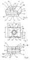
- the cutting insert 10 designed as an indexable insert after 1 to 4 consists of an essentially cubic body, of the two larger surfaces 11 lying parallel to one another and 12, which has long cutting edges on the long sides 13 can be limited.
- Each of the long cutting edges has a middle constriction 131, which is between two respective Cutting edge ends 132 and 133 are located.
- the cutting edge ends 132 and 133 are of the same length, their absolute size depends on the machining conditions.
- the central area 131 of the cutting edge is in each case "used" when engaging the cutting edge end 132 or 133, which is possible because the wear on machining on Cutting edge end is at least twice as high as in the Cutting edge center.
- the ratio of the cutting edge ends 132 or 133 to 131 is about 1: 1.4 in the present case, can, however, in principle between 1: 2 and without middle range to get voted.
- the ratio of length to width a / b is according to the invention between 1.2 and 2.
- the small end faces 15, 16 on the end face go over a rounded edges 14 into the larger areas 11, 12, whereby each is approximately quarter-circular on the longitudinal surfaces 17 trained cutting edges 18, namely four on each Result in the corner of the longitudinal surface.
- the cutting insert 10 has a central mounting hole 19 for a clamping screw or one Head for a toggle or eccentric tension.
- the opposite the adjacent surface areas, i.e. the chip mold recesses 21 protrudes by at least 2 mm.
- the web 20 has one Width of at least 1.5 mm to ensure the stability of the plate enable. 4 shows the side view Rake angle ⁇ positive and in the present case is approximately 10 °.
- the troughs 21 each follow the long ones Cutting edges 13 have a substantially flat edge before they over the radius of a truncated cone as a connector to the Pass over bridge 20.
- the entire design of the cutting insert is mirror-symmetrical, namely in each axis direction of a central cutting plane.
- the cutting insert according to Fig. 1 to 4 is tangential screwed, so they can often in the pin bearing area when machining crankshafts occurring larger measurements of the cheeks like this be covered that a depth of cut is possible, the greater than 0.5 x a.
- the middle one can be used here Area 131 of the long cutting edge 13 both when cutting with the cutting edge 132 as well as with the cutting edge 133 each "with to be used.
- the described, specially shaped chip chamber (Mulde 21) is specially designed for the installation of the cutting insert in tangential Location equipped.
- the web 20, between the long than Main cutting long cutting edges separates on the one hand spatially the long cutting edges 13 from each other and serves in particular as a fixing system when clamping.
- the distance the wall of the hole 19 to the cutting edge 13 is on the narrowest point at least 2 mm.
- FIGS. 1 to 4 illustrated indexable insert which has 8 usable cutting edges, modified version shown with only 4 cutting edges.
- the structure of the cutting insert 100 corresponds to that in detail of the cutting insert 10 with the proviso that approximately along the Longitudinal median plane, i.e. made a cut at the level of the webs 20 is (of course the edges 101, 102 rounded are.
- the central region 103 of the chip mold cavity in Formed a web one opposite the edge Chip mold trough 104 has the above shape, this Bridge is made much larger than 1.5 mm for reasons of space is.
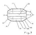
- the cutting insert 10 designed as an indexable insert after 6 to 9 consists of an essentially cubic body, of the two larger surfaces 11 lying parallel to one another and 12, which has long cutting edges on the long sides 13 can be limited.
- Each of the long cutting edges has a middle constriction 131, which is between two respective Cutting edge ends 132 and 133 are located.
- the cutting edge ends 132 and 133 are of equal length, with their absolute dimensions according to the machining conditions.
- the middle one Area 131 of the cutting edge is in each case when the Cutting edge end 132 or 133 "shared", which is possible because the wear on the cutting edge end is at least twice as high as in the center of the cutting edge.
- the ratio of the cutting edge ends 132 or 133 to 131 is in the present case at approx. 1: 1.4, but can in principle between 1: 2 and without a middle range.
- the ratio of length to width a / b is according to the invention between 1.2 and 2.
- the small end faces 15, 16 on the end face merge on one side via a respective rounded edge 14 into the larger areas 11, 12, which results in cutting edges 18 of approximately quarter-circular design on the longitudinal faces 17, namely two at each corner of the longitudinal face.
- the cutting insert has a bevelled surface 180 which is flat and is arranged at an obtuse angle to the small end surface. This surface 180 merges into the adjacent surfaces 15 and 16 and 11 and 12 via rounded edges.
- the radius R 2 shown in FIG. 8, which also corresponds to the radius R for the rounded edge 18, is 1.6 mm, whereas the radius R 1 is chosen to be 1.6 mm.
- the cutting insert according to FIG. 9 differs from the cutting insert according to FIGS. 6 to 8 in that in each of the corner areas there are respectively inclined connecting surfaces 180, the extension of which with the respective end surface 15 or 16 has an angle ⁇ of more than 0 ° and forms less than 90 °.
- the dimensioning of the radii R 1 and R 2 corresponds to that described for FIG. 8.
- the cutting insert 10 has a central fastening hole for a clamping screw or a head for a toggle lever or Eccentric tension.
- the opposite the adjacent surface areas, i.e. the chip mold recesses 21 protrudes by at least 2 mm.
- the web 20 has one Width of at least 1.5 mm to ensure the stability of the plate enable.
- the rake angle formed by the troughs 21 is positive and is about 10 ° in the present case.
- the hollows 21 each have following the long cutting edges 13 a substantially flat edge before going over radius of a truncated cone as a connecting piece to the web 20.
- the overall design of the cutting insert according to FIG. 9 is mirror-symmetrical, in each axial direction of a central one Cutting plane. If the cutting insert according to FIGS. 6 to 9 screwed tangentially, so they can often be in the pin bearing area larger oversizes that occur when machining crankshafts the cheeks are covered so that a depth of cut is possible is greater than 0.5 x a. As already mentioned, can here the central region 131 of the long cutting edge 13 both when cutting with the cutting edge 132 and with the Cutting edge 133 can be "used".
- the described, specially shaped chip chamber (trough 21) is specially equipped for the installation of the cutting insert in a tangential position.
- the web 20, between the long cutting edges serving as main cutting edges, on the one hand spatially separates the long cutting edges 13 from one another and serves in particular as a fixing system when clamping.
- the distance between the wall of the hole 19 and the cutting edge 13 is at least 2 mm at the narrowest point.
- FIG. 5 is for radial clamping Installation position provided, in particular in a milling tool, at the alternating cutting inserts in a row tangential and radial installation position are arranged.
- FIG. 10 illustrates the two cutting inserts 10 and 100 in tangential and radial installation position shows at the radial feed rate.
- the cutting insert 100 has the greatest possible cutting depth d, which in is essentially determined by the dimension of the short edge or lies below.
- a cutting width "c" Fig. 10
- the maxiamle Cutting depth of the cutting insert 100 in a tangential position corresponds approximately to the sum of the length of the cutting edge sections 132 or 133 and 131.
- Fig. 11 shows a 90 ° offset representation of the insert arrangement 10, which shows that the cutting inserts 10 and 100 alternately in alternating order are arranged circumferentially and side by side.
- a milling tool can also be used an arrangement of cutting inserts 10 can be selected 12 and 13 can be seen.
- the cutting inserts 10 are in in this case, one behind the other and next to each other on the circumference disc-shaped tool holder arranged, preferably such that the cutting inserts arranged one behind the other one row opposite the cutting inserts of the parallel ones Row are staggered.
- Fig. 10 dimension c
Landscapes
- Engineering & Computer Science (AREA)
- Mechanical Engineering (AREA)
- Milling Processes (AREA)
Abstract
Claims (10)
- Insert de coupe (10) avec un corps de base pour l'essentiel cubique qui est réalisé comme plaquette réversible avec huit tranchants utilisables,caractérisé par le fait queavec deux surfaces planes plus grandes (11, 12) disposées parallèlement l'une à l'autre et percées d'un trou de fixation (19) et avec quatre faces latérales respectivement contiguës à ces premières, à savoir deux petites surfaces terminales frontales (15, 16) parallèles entre elles et des surfaces longitudinales plus grandes (17) qui présentent, respectivement au milieu le long de leur axe longitudinal, une entretoise (20) saillante qui sert de surface d'appui lors du serrage de l'insert de coupe (10) dans un support d'outils,les surfaces plus grandes (11, 12) débouchant par une arête arrondie (14) dans les petites surfaces terminales (15, 16), de sorte que, sur le grand côté (17), des tranchants (18) à peu près en forme de quart de cercle sont formés comme lignes limites vers les surfaces terminales (15, 16) dans la zone du coin,les longs tranchants (13) comme lignes limites entre les surfaces plus grandes (11, 12) et la surface longitudinale respectivement contiguë (17) étant courbés de manière arquée, de sorte que l'on obtient un corps à symétrie spéculaire par rapport au plan médian longitudinal et au plan médian transversal,
les longs tranchants (13) avec leur extrémité respective et l'arête arrondie (14) entre la petite surface terminale et la surface plus grande forment un angle 70°<(90°-β)<90°. - Insert de coupe selon la revendication 1, caractérisé par le fait que les longs tranchants sont réalisés de manière concave ou se composent de portions (131 à 133) respectivement contiguës l'une à l'autre sous un angle (γ) > 180°, qui, de préférence, sont arrondies et/ou dont la zone centrale (131) est réalisée de façon linéaire, de préférence sur une longueur allant jusqu'à 1/2 de la longueur totale du tranchant.
- Insert de coupe selon l'une des revendications 1 ou 2, caractérisé par le fait que l'angle de coupe (α) entre la verticale et l'orientation du creux (21) est compris entre 0°<α<20° et/ou que l'angle de coupe latérale (β) entre les surfaces terminales frontales plus petites (15, 16) et les extrémités de tranchant (132, 133) est compris entre 0° et 20° et/ou que la largeur de l'entretoise (20) dans la zone centrale est de 1,5 mm du moins.
- Insert de coupe selon l'une des revendications 1 à 3, caractérisé par le fait que le rapport longueur/largeur (a/b) des surfaces plus grandes (11, 12) et ainsi des longs tranchants respectifs (13) aux arêtes arrondies plus courtes (14) est compris entre 1,2 et 2, et/ou que la distance la plus courte (c) du bord du trou de fixation au tranchant long (13) est inférieure à 2 mm.
- Insert de coupe (10) avec un corps de base pour l'essentiel cubique qui est réalisé comme plaquette réversible avec huit tranchants utilisables,caractérisé par le fait queavec deux surfaces planes plus grandes (11, 12) disposées parallèlement l'une à l'autre et percées d'un trou de fixation (19) et avec quatre faces latérales respectivement contiguës à ces premières, à savoir deux petites surfaces terminales frontales (15, 16) parallèles entre elles et des surfaces longitudinales plus grandes (17) qui présentent, respectivement au milieu le long de leur axe longitudinal, une entretoise (20) saillante qui sert de surface d'appui lors du serrage de l'insert de coupe (10) dans un support d'outils,les surfaces plus grandes (11, 12) débouchant par des surfaces de jonction (180) ou une arête arrondie (14) dans les petites surfaces terminales (15, 16), de sorte que, sur le grand côté (17), on obtient des tranchants (18) formés de manière correspondante, comme lignes limites vers les surfaces terminales (15, 16) dans la zone du coin,les longs tranchants (13) comme lignes limites entre les surfaces plus grandes (11, 12) et la surface longitudinale respectivement contiguë (17) étant courbés de manière arquée, de sorte que l'on obtient un corps à symétrie spéculaire par rapport au plan médian longitudinal et au plan médian transversal,
les longs tranchants (13) avec leur extrémité respective et l'arête arrondie (14) entre la petite surface terminale et la surface plus grande forment un angle 70°<(90°-β)<90° et que du moins une des surfaces de jonction (180) entre les surfaces plus grandes (11, 12) et les surfaces terminales plus petites (15, 16) est un plan qui est disposé sous un angle obtus < 180° par rapport à la petite surface terminale (15, 16) et qui forme sur le grand côté un tranchant secondaire (180). - Insert de coupe selon la revendication 5, caractérisé par le fait que les longs tranchants se composent de portions (131 à 133) respectivement contiguës l'une à l'autre sous un angle (γ) > 180° et que la longueur du tranchant secondaire (180) est au maximum aussi grande que la longueur de chacune des portions extérieures (132, 133) et/ou que le plan disposé sous un angle (κ) et les surfaces contiguës se rencontrent par des arêtes arrondies, de préférence le rayon (R1) entre le plan et la surface plus grande (12) étant compris entre 0<R1≤3 mm et/ou que le rayon R2 entre le plan et la petite surface terminale (15, 16) étant compris entre 1 mm<R2≤4 mm.
- Outil de fraisage avec une multiplicité d'inserts de coupe serrés, caractérisé par le fait qu'une partie au moins des inserts de coupe (10) serrés de façon tangentielle est réalisée selon l'une des revendications 1 à 6.
- Outil de fraisage selon la revendication 7, caractérisé par le fait que, en sus, il y a des inserts de coupe (100) serrés de façon radiale, dont une partie au moins est réalisée selon l'une des revendications 1 à 4, ou ils présentent une configuration qui correspond à la moitié résultant d'une coupe le long du plan médian longitudinal de l'insert de coupe (10) selon l'une des revendications 1 à 4.
- Outil de fraisage selon la revendication 7 ou 8, caractérisé par le fait que le porte-outils est réalisé comme disque et présente des inserts de coupe (10, 100) serrés, en alternance, de façon radiale et de façon tangentielle, la largeur du disque étant plus petite que la double longueur de l'inesrt de coupe (10) selon l'une des revendications 1 à 4.
- Outil de fraisage selon l'une des revendications 7 à 9, caractérisé par le fait que les surfaces qui sont contiguës à l'entretoise (20) sont réalisées comme chanfrein (22), et/ou qu'un chanfrein contigu aux tranchants présente une largeur allant jusqu'à 0,2 mm et un angle de chanfrein qui est compris entre 0° et 20°.
Applications Claiming Priority (5)
| Application Number | Priority Date | Filing Date | Title |
|---|---|---|---|
| DE19704931 | 1997-02-10 | ||
| DE19704931A DE19704931C1 (de) | 1997-02-10 | 1997-02-10 | Schneideinsatz und Fräswerkzeug |
| DE19736379A DE19736379A1 (de) | 1997-02-10 | 1997-08-21 | Schneideinsatz und Fräswerkzeug |
| DE19736379 | 1997-08-21 | ||
| PCT/DE1998/000310 WO1998034747A1 (fr) | 1997-02-10 | 1998-02-03 | Plaquette de coupe et outil de fraisage |
Publications (2)
| Publication Number | Publication Date |
|---|---|
| EP0958085A1 EP0958085A1 (fr) | 1999-11-24 |
| EP0958085B1 true EP0958085B1 (fr) | 2001-04-04 |
Family
ID=26033797
Family Applications (1)
| Application Number | Title | Priority Date | Filing Date |
|---|---|---|---|
| EP98909329A Expired - Lifetime EP0958085B1 (fr) | 1997-02-10 | 1998-02-03 | Plaquette de coupe et outil de fraisage |
Country Status (5)
| Country | Link |
|---|---|
| US (1) | US6227772B1 (fr) |
| EP (1) | EP0958085B1 (fr) |
| CA (1) | CA2280121C (fr) |
| DE (2) | DE19736379A1 (fr) |
| WO (1) | WO1998034747A1 (fr) |
Cited By (4)
| Publication number | Priority date | Publication date | Assignee | Title |
|---|---|---|---|---|
| US6979469B2 (en) | 2000-12-12 | 2005-12-27 | L'Oréal, S.A. | Use of polyamide polymer in a mascara composition comprising at least one inert filler |
| USD777230S1 (en) | 2015-07-16 | 2017-01-24 | Kennametal Inc | Double-sided tangential cutting insert |
| USD778330S1 (en) | 2015-07-16 | 2017-02-07 | Kennametal Inc. | Double-sided tangential cutting insert |
| US9981323B2 (en) | 2015-07-16 | 2018-05-29 | Kennametal Inc. | Double-sided tangential cutting insert and cutting tool system using the same |
Families Citing this family (52)
| Publication number | Priority date | Publication date | Assignee | Title |
|---|---|---|---|---|
| IL129297A (en) | 1998-07-13 | 2002-12-01 | Iscar Ltd | Tangential cutting insert |
| DE10027945A1 (de) * | 2000-06-08 | 2002-01-10 | Widia Gmbh | Scheibenfräser |
| JP3472752B2 (ja) * | 2000-08-03 | 2003-12-02 | 住友電気工業株式会社 | スローアウェイチップ及びそれを用いたピンミラーカッタ |
| IL140104A (en) * | 2000-12-05 | 2006-06-11 | Amir Satran | Rotary cutting tool |
| IL145342A0 (en) * | 2001-09-10 | 2002-06-30 | Iscar Ltd | Cutting insert |
| CH693203A5 (de) * | 2002-02-18 | 2003-04-15 | Ejup Sulejmani | Mehrzweckwerkzeug. |
| IL153252A0 (en) * | 2002-06-04 | 2003-07-06 | Iscar Ltd | Tangential cutting insert and milling cutter |
| CN100548551C (zh) * | 2002-12-04 | 2009-10-14 | 伊斯卡有限公司 | 切向切削镶块和铣削刀具 |
| US7094007B2 (en) * | 2002-12-04 | 2006-08-22 | Iscar Ltd. | Tangential cutting insert and milling cutter |
| IL155288A (en) * | 2003-04-08 | 2007-09-20 | Amir Satran | Tangential cutting insert and milling cutter |
| US7008146B2 (en) * | 2003-07-21 | 2006-03-07 | Kennametal Inc. | Milling cutter with tangentially mounted inserts |
| CN100441640C (zh) * | 2003-09-26 | 2008-12-10 | 三菱化学株式会社 | 炭黑和使用炭黑的记录液 |
| WO2005117813A1 (fr) | 2004-05-26 | 2005-12-15 | L'oreal | Preparations de mousse cosmetique |
| US7104735B2 (en) * | 2004-09-02 | 2006-09-12 | Ingersoll Cutting Tool Company | Tangential cutting insert and milling cutter |
| DE102005025815A1 (de) * | 2005-06-02 | 2006-12-07 | Kennametal Widia Produktions Gmbh & Co. Kg | Schneideinsatz, insbesondere zur Kurbelwellenbearbeitung |
| DE102005037310A1 (de) * | 2005-06-02 | 2006-12-07 | Kennametal Widia Produktions Gmbh & Co. Kg | Schneideinsatz |
| JP4491404B2 (ja) | 2005-11-07 | 2010-06-30 | 住友電工ハードメタル株式会社 | 刃先交換式チップと刃先交換式隅削りフライスカッタ |
| DE102005054434B4 (de) * | 2005-11-15 | 2009-09-24 | Kennametal Inc. | Wendeschneidplatte mit zwei Teilkörpern |
| AT503333B1 (de) * | 2006-03-07 | 2008-06-15 | Boehlerit Gmbh & Co Kg | Wendeschneidplatte für fräswerkzeuge |
| SE530025C2 (sv) * | 2006-06-21 | 2008-02-12 | Seco Tools Ab | Vändbart frässkär och verktyg med trigonformat tangentiellt monterat skär |
| USD572279S1 (en) * | 2006-07-05 | 2008-07-01 | Sumitomo Electric Hardmetal Corp. | Throwaway insert for a pin mirror cutter |
| DE102006034673A1 (de) * | 2006-07-24 | 2008-01-31 | Walter Ag | Kurbelwellenfräser |
| MX2009013985A (es) * | 2007-06-21 | 2010-04-09 | Ceramtec Ag | Inserto negativo que tiene doble superficie de separacion positiva. |
| US8141464B2 (en) * | 2007-08-23 | 2012-03-27 | Komatsu Ntc Ltd. | Milling cutter of crank shaft miller, and cutter tip and cutter tip set for milling cutter of crank shaft miller |
| JPWO2009034633A1 (ja) * | 2007-09-13 | 2010-12-16 | 株式会社タンガロイ | ラジアスカッタ用スローアウェイチップ、およびこれを装着したスローアウェイ式ラジアスカッタ |
| USD638041S1 (en) * | 2010-08-11 | 2011-05-17 | Mitsubishi Materials Corporation | Cutting insert |
| USD637214S1 (en) * | 2010-08-11 | 2011-05-03 | Mitsubishi Materials Corporation | Cutting insert |
| SE535171C2 (sv) * | 2010-09-24 | 2012-05-08 | Sandvik Intellectual Property | Kuggfräs jämte bytbart skär härför |
| US8708008B2 (en) * | 2010-11-03 | 2014-04-29 | Sandvik Intellectual Property Ab | Shaped carbide tips, carbide-tipped teeth, and tools with same |
| WO2012059395A1 (fr) * | 2010-11-03 | 2012-05-10 | Seco Tools Ab | Plaquette de coupe avec surface rainurée délimitant une pluralité de surfaces de support |
| DE102011107789B4 (de) * | 2011-07-18 | 2015-05-28 | Kennametal Inc. | Zahnradfräser-Schneideinsatz und Zahnradfräser mit einem solchen Zahnradfräser-Schneideinsatz |
| JP5790765B2 (ja) * | 2011-07-29 | 2015-10-07 | 株式会社タンガロイ | 切削インサートおよび回転切削工具 |
| US9079251B2 (en) * | 2011-10-25 | 2015-07-14 | Kennametal Inc. | Cutting inserts having discontiguous clearance faces |
| US8790049B2 (en) * | 2012-02-07 | 2014-07-29 | Iscar, Ltd. | Indexable double-negative cutting insert having protruding side abutment surfaces and cutting tool |
| US20150056028A1 (en) * | 2012-03-30 | 2015-02-26 | Ceramtec Gmbh | Cutting plate having flank faces and contact faces on the peripheral geometry |
| SE536646C2 (sv) * | 2012-09-07 | 2014-04-29 | Sandvik Intellectual Property | Fräsverktyg samt skärkit för fräsverktyg |
| US9616506B2 (en) * | 2013-03-26 | 2017-04-11 | Sumitomo Electric Hardmetal Corp. | Cutting insert and face milling cutter using the same |
| US9421615B2 (en) * | 2014-04-10 | 2016-08-23 | Iscar, Ltd. | Cutting tool and cutting insert having exactly four cutting portions therefor |
| US9901992B2 (en) * | 2014-12-23 | 2018-02-27 | Iscar, Ltd. | Ramping insert and high-feed milling tool assembly |
| US9636758B2 (en) * | 2014-12-23 | 2017-05-02 | Iscar, Ltd. | Ramping insert and high-feed milling tool assembly |
| JP1541378S (fr) * | 2015-04-02 | 2016-01-12 | ||
| US20170120351A1 (en) * | 2015-11-03 | 2017-05-04 | Kennametal Inc. | Double-sided cutting inserts with positive clearance face geometry |
| KR101814642B1 (ko) * | 2015-11-04 | 2018-01-03 | 한국야금 주식회사 | 고이송 양면형 절삭 인서트 및 이를 장착한 절삭 공구 |
| USD794101S1 (en) * | 2015-12-28 | 2017-08-08 | Taegutec Ltd. | Cutting insert |
| USD794102S1 (en) * | 2015-12-28 | 2017-08-08 | Taegutec Ltd. | Cutting insert |
| JP6612152B2 (ja) | 2016-03-03 | 2019-11-27 | 住友電工ハードメタル株式会社 | 切削インサートおよび切削工具 |
| US10590615B2 (en) * | 2016-06-28 | 2020-03-17 | Vigor Industrial Llc | Orthotropic deck |
| EP3456450B1 (fr) * | 2017-09-13 | 2022-12-21 | Sandvik Intellectual Property AB | Plaquette de coupe et outil de fraisage de vilebrequin |
| JP6424975B1 (ja) * | 2018-02-07 | 2018-11-21 | 三菱マテリアル株式会社 | 切削インサートおよび刃先交換式切削工具 |
| JP6972513B1 (ja) * | 2021-02-10 | 2021-11-24 | 株式会社タンガロイ | 切削インサート |
| EP4197678A1 (fr) * | 2021-12-17 | 2023-06-21 | Seco Tools AB | Insert de coupe tangentiel à double face |
| CN119457220B (zh) * | 2025-01-14 | 2025-07-22 | 赣州澳克泰工具技术有限公司 | 一种双面切削刀片及切削刀具 |
Family Cites Families (14)
| Publication number | Priority date | Publication date | Assignee | Title |
|---|---|---|---|---|
| DE1477374C3 (de) * | 1962-03-20 | 1974-02-21 | Hans 8502 Zirndorf Heinlein | Schneidwerkzeug für die spanabhebende Bearbeitung |
| US3694876A (en) * | 1970-08-28 | 1972-10-03 | Ingersoll Milling Machine Co | Indexable cutting insert and holder therefor |
| US3762005A (en) | 1970-08-28 | 1973-10-02 | Ingersoll Milling Machine Co | Indexable cutting insert |
| US4124326A (en) * | 1977-01-03 | 1978-11-07 | The Valeron Corporation | Cutting insert with raised cutting edge |
| DE8317114U1 (de) | 1983-06-11 | 1983-10-06 | Hartmetall-Werkzeugfabrik Paul Horn Gmbh, 7400 Tuebingen | Drehwerkzeug mit einem halter fuer einen auswechselbaren schneideinsatz |
| SE448431B (sv) | 1985-07-03 | 1987-02-23 | Santrade Ltd | Vendsker for spanavskiljande bearbetning |
| US4789273A (en) | 1987-03-02 | 1988-12-06 | General Motors Of Canada Ltd. | Milling cutter |
| DE68912539T2 (de) | 1988-12-02 | 1994-05-11 | Gen Motors Corp | Scheibenförmigen Fräser mit verbessertem Schneidkörpen. |
| SE470093B (sv) | 1992-04-02 | 1993-11-08 | Sandvik Ab | Skär för skiv- eller planfräsar, samt fräsverktyg för sådana skär |
| DE4342557C2 (de) * | 1993-12-14 | 1996-04-11 | Felix Leeb | Fräsbohrwerkzeug |
| US5639189A (en) * | 1994-11-08 | 1997-06-17 | Ingersoll Cutting Tool Company | Plunge milling insert |
| DE19516946A1 (de) | 1995-05-11 | 1996-11-14 | Widia Gmbh | Fräswerkzeug |
| DE29516668U1 (de) | 1995-10-21 | 1995-12-14 | Ingersoll, Maschinen und Werkzeuge, GmbH, 57299 Burbach | Werkzeug zur spanenden Bearbeitung von Werkst}cken |
| DE19704931C1 (de) | 1997-02-10 | 1998-03-12 | Widia Gmbh | Schneideinsatz und Fräswerkzeug |
-
1997
- 1997-08-21 DE DE19736379A patent/DE19736379A1/de not_active Withdrawn
-
1998
- 1998-02-03 WO PCT/DE1998/000310 patent/WO1998034747A1/fr not_active Ceased
- 1998-02-03 EP EP98909329A patent/EP0958085B1/fr not_active Expired - Lifetime
- 1998-02-03 DE DE59800591T patent/DE59800591D1/de not_active Expired - Lifetime
- 1998-02-03 US US09/355,294 patent/US6227772B1/en not_active Expired - Lifetime
- 1998-02-03 CA CA002280121A patent/CA2280121C/fr not_active Expired - Fee Related
Cited By (4)
| Publication number | Priority date | Publication date | Assignee | Title |
|---|---|---|---|---|
| US6979469B2 (en) | 2000-12-12 | 2005-12-27 | L'Oréal, S.A. | Use of polyamide polymer in a mascara composition comprising at least one inert filler |
| USD777230S1 (en) | 2015-07-16 | 2017-01-24 | Kennametal Inc | Double-sided tangential cutting insert |
| USD778330S1 (en) | 2015-07-16 | 2017-02-07 | Kennametal Inc. | Double-sided tangential cutting insert |
| US9981323B2 (en) | 2015-07-16 | 2018-05-29 | Kennametal Inc. | Double-sided tangential cutting insert and cutting tool system using the same |
Also Published As
| Publication number | Publication date |
|---|---|
| WO1998034747A1 (fr) | 1998-08-13 |
| CA2280121A1 (fr) | 1998-08-13 |
| CA2280121C (fr) | 2006-01-17 |
| EP0958085A1 (fr) | 1999-11-24 |
| DE59800591D1 (de) | 2001-05-10 |
| US6227772B1 (en) | 2001-05-08 |
| DE19736379A1 (de) | 1999-02-25 |
Similar Documents
| Publication | Publication Date | Title |
|---|---|---|
| WO1998034747A1 (fr) | Plaquette de coupe et outil de fraisage | |
| DE68907004T2 (de) | Schneideinsatz. | |
| EP1253989B1 (fr) | Piece de coupe rapportee et outil de fraisage correspondant | |
| EP0587592B1 (fr) | Insert de coupe polygonal ou rond | |
| DE69311341T2 (de) | Indexierbarer schneideinsatz für drehende schneidwerkzeuge | |
| EP0884124B1 (fr) | Fraise avec ajustement axial | |
| EP0995528B1 (fr) | Fraise avec des plaquettes de coupe indexables | |
| DE10231339B3 (de) | Tangential-Wendeschneidplatte | |
| DE69110236T2 (de) | Ein Schneideinsatz für einen Fräser. | |
| DE69619378T2 (de) | Werkzeug für metallbearbeitung | |
| EP0719193B1 (fr) | Plaquette | |
| DE69732385T2 (de) | Frässchneideinsatz | |
| DE69408010T2 (de) | Verbessertes Schneidwerkzeug und Schneideinsatz dafür | |
| EP1486279A1 (fr) | Plaquette de coupe pour tourner et fraiser | |
| EP0677350A1 (fr) | Plaquette de coupe, en particulier plaquette de coupe indexable | |
| DE19927545A1 (de) | Schneideinsatz für Nockenwellenfräser und Scheibenfräser hierfür | |
| DE4201112C2 (de) | Schneideinsatz | |
| EP1140408B1 (fr) | Piece de coupe rapportee et outil muni d'une piece de coupe rapportee | |
| DE19704931C1 (de) | Schneideinsatz und Fräswerkzeug | |
| DE2334547C3 (de) | Wendeschneidplatte | |
| WO2003022495A1 (fr) | Matrice de decoupage pour outils servant a l'usinage de pieces par enlevement de copeaux | |
| EP3030369B1 (fr) | Insert de coupe d'une fraise | |
| DE68909556T2 (de) | Fräser mit Schneideeinsätzen. | |
| EP1184117B1 (fr) | Outil de coupe avec support mutuel des plaquettes de coupe | |
| DE10333621B4 (de) | Schneideinsatz |
Legal Events
| Date | Code | Title | Description |
|---|---|---|---|
| PUAI | Public reference made under article 153(3) epc to a published international application that has entered the european phase |
Free format text: ORIGINAL CODE: 0009012 |
|
| 17P | Request for examination filed |
Effective date: 19990712 |
|
| AK | Designated contracting states |
Kind code of ref document: A1 Designated state(s): DE FR GB IT |
|
| GRAG | Despatch of communication of intention to grant |
Free format text: ORIGINAL CODE: EPIDOS AGRA |
|
| 17Q | First examination report despatched |
Effective date: 20000724 |
|
| GRAG | Despatch of communication of intention to grant |
Free format text: ORIGINAL CODE: EPIDOS AGRA |
|
| GRAH | Despatch of communication of intention to grant a patent |
Free format text: ORIGINAL CODE: EPIDOS IGRA |
|
| GRAH | Despatch of communication of intention to grant a patent |
Free format text: ORIGINAL CODE: EPIDOS IGRA |
|
| GRAA | (expected) grant |
Free format text: ORIGINAL CODE: 0009210 |
|
| AK | Designated contracting states |
Kind code of ref document: B1 Designated state(s): DE FR GB IT |
|
| GBT | Gb: translation of ep patent filed (gb section 77(6)(a)/1977) |
Effective date: 20010404 |
|
| REF | Corresponds to: |
Ref document number: 59800591 Country of ref document: DE Date of ref document: 20010510 |
|
| ET | Fr: translation filed | ||
| ITF | It: translation for a ep patent filed | ||
| REG | Reference to a national code |
Ref country code: GB Ref legal event code: IF02 |
|
| PLBE | No opposition filed within time limit |
Free format text: ORIGINAL CODE: 0009261 |
|
| STAA | Information on the status of an ep patent application or granted ep patent |
Free format text: STATUS: NO OPPOSITION FILED WITHIN TIME LIMIT |
|
| 26N | No opposition filed | ||
| PGFP | Annual fee paid to national office [announced via postgrant information from national office to epo] |
Ref country code: IT Payment date: 20110221 Year of fee payment: 14 |
|
| PGFP | Annual fee paid to national office [announced via postgrant information from national office to epo] |
Ref country code: FR Payment date: 20120221 Year of fee payment: 15 |
|
| PGFP | Annual fee paid to national office [announced via postgrant information from national office to epo] |
Ref country code: GB Payment date: 20120201 Year of fee payment: 15 |
|
| PG25 | Lapsed in a contracting state [announced via postgrant information from national office to epo] |
Ref country code: IT Free format text: LAPSE BECAUSE OF NON-PAYMENT OF DUE FEES Effective date: 20120203 |
|
| GBPC | Gb: european patent ceased through non-payment of renewal fee |
Effective date: 20130203 |
|
| REG | Reference to a national code |
Ref country code: FR Ref legal event code: ST Effective date: 20131031 |
|
| PG25 | Lapsed in a contracting state [announced via postgrant information from national office to epo] |
Ref country code: GB Free format text: LAPSE BECAUSE OF NON-PAYMENT OF DUE FEES Effective date: 20130203 Ref country code: FR Free format text: LAPSE BECAUSE OF NON-PAYMENT OF DUE FEES Effective date: 20130228 |
|
| PGFP | Annual fee paid to national office [announced via postgrant information from national office to epo] |
Ref country code: DE Payment date: 20170227 Year of fee payment: 20 |
|
| REG | Reference to a national code |
Ref country code: DE Ref legal event code: R071 Ref document number: 59800591 Country of ref document: DE |