EP0958113B1 - Method and apparatus for automatically laying, cutting and removing, on and from a continuously moving conveyor - Google Patents
Method and apparatus for automatically laying, cutting and removing, on and from a continuously moving conveyor Download PDFInfo
- Publication number
- EP0958113B1 EP0958113B1 EP98905381A EP98905381A EP0958113B1 EP 0958113 B1 EP0958113 B1 EP 0958113B1 EP 98905381 A EP98905381 A EP 98905381A EP 98905381 A EP98905381 A EP 98905381A EP 0958113 B1 EP0958113 B1 EP 0958113B1
- Authority
- EP
- European Patent Office
- Prior art keywords
- cut
- cutting
- roll
- shapes
- automatic
- Prior art date
- Legal status (The legal status is an assumption and is not a legal conclusion. Google has not performed a legal analysis and makes no representation as to the accuracy of the status listed.)
- Expired - Lifetime
Links
- 238000005520 cutting process Methods 0.000 title claims abstract description 63
- 238000000034 method Methods 0.000 title claims abstract description 25
- 239000000463 material Substances 0.000 claims abstract description 82
- 238000004519 manufacturing process Methods 0.000 claims abstract description 36
- 239000004744 fabric Substances 0.000 claims description 95
- 238000000151 deposition Methods 0.000 claims description 20
- 238000007726 management method Methods 0.000 claims description 11
- 230000008021 deposition Effects 0.000 claims description 10
- 238000005096 rolling process Methods 0.000 claims description 5
- 238000013523 data management Methods 0.000 claims description 4
- 238000012856 packing Methods 0.000 claims description 3
- 238000003860 storage Methods 0.000 claims description 3
- 230000004308 accommodation Effects 0.000 claims 1
- 230000000087 stabilizing effect Effects 0.000 claims 1
- 238000012384 transportation and delivery Methods 0.000 claims 1
- 239000010985 leather Substances 0.000 abstract 1
- 239000010410 layer Substances 0.000 description 6
- 238000005457 optimization Methods 0.000 description 5
- 239000002356 single layer Substances 0.000 description 5
- 238000004422 calculation algorithm Methods 0.000 description 2
- 238000010586 diagram Methods 0.000 description 2
- 230000003287 optical effect Effects 0.000 description 2
- 239000002699 waste material Substances 0.000 description 2
- 238000004458 analytical method Methods 0.000 description 1
- 230000005540 biological transmission Effects 0.000 description 1
- 239000003086 colorant Substances 0.000 description 1
- 238000005516 engineering process Methods 0.000 description 1
- 239000000835 fiber Substances 0.000 description 1
- 230000002452 interceptive effect Effects 0.000 description 1
- 230000007246 mechanism Effects 0.000 description 1
- 230000000737 periodic effect Effects 0.000 description 1
- 238000011144 upstream manufacturing Methods 0.000 description 1
Images





Classifications
-
- B—PERFORMING OPERATIONS; TRANSPORTING
- B26—HAND CUTTING TOOLS; CUTTING; SEVERING
- B26D—CUTTING; DETAILS COMMON TO MACHINES FOR PERFORATING, PUNCHING, CUTTING-OUT, STAMPING-OUT OR SEVERING
- B26D5/00—Arrangements for operating and controlling machines or devices for cutting, cutting-out, stamping-out, punching, perforating, or severing by means other than cutting
- B26D5/007—Control means comprising cameras, vision or image processing systems
-
- B—PERFORMING OPERATIONS; TRANSPORTING
- B26—HAND CUTTING TOOLS; CUTTING; SEVERING
- B26D—CUTTING; DETAILS COMMON TO MACHINES FOR PERFORATING, PUNCHING, CUTTING-OUT, STAMPING-OUT OR SEVERING
- B26D5/00—Arrangements for operating and controlling machines or devices for cutting, cutting-out, stamping-out, punching, perforating, or severing by means other than cutting
-
- B—PERFORMING OPERATIONS; TRANSPORTING
- B26—HAND CUTTING TOOLS; CUTTING; SEVERING
- B26D—CUTTING; DETAILS COMMON TO MACHINES FOR PERFORATING, PUNCHING, CUTTING-OUT, STAMPING-OUT OR SEVERING
- B26D5/00—Arrangements for operating and controlling machines or devices for cutting, cutting-out, stamping-out, punching, perforating, or severing by means other than cutting
- B26D5/005—Computer numerical control means
-
- B—PERFORMING OPERATIONS; TRANSPORTING
- B26—HAND CUTTING TOOLS; CUTTING; SEVERING
- B26D—CUTTING; DETAILS COMMON TO MACHINES FOR PERFORATING, PUNCHING, CUTTING-OUT, STAMPING-OUT OR SEVERING
- B26D7/00—Details of apparatus for cutting, cutting-out, stamping-out, punching, perforating, or severing by means other than cutting
- B26D7/18—Means for removing cut-out material or waste
-
- B—PERFORMING OPERATIONS; TRANSPORTING
- B26—HAND CUTTING TOOLS; CUTTING; SEVERING
- B26F—PERFORATING; PUNCHING; CUTTING-OUT; STAMPING-OUT; SEVERING BY MEANS OTHER THAN CUTTING
- B26F1/00—Perforating; Punching; Cutting-out; Stamping-out; Apparatus therefor
- B26F1/38—Cutting-out; Stamping-out
- B26F1/3806—Cutting-out; Stamping-out wherein relative movements of tool head and work during cutting have a component tangential to the work surface
- B26F1/3813—Cutting-out; Stamping-out wherein relative movements of tool head and work during cutting have a component tangential to the work surface wherein the tool head is moved in a plane parallel to the work in a coordinate system fixed with respect to the work
-
- B—PERFORMING OPERATIONS; TRANSPORTING
- B26—HAND CUTTING TOOLS; CUTTING; SEVERING
- B26D—CUTTING; DETAILS COMMON TO MACHINES FOR PERFORATING, PUNCHING, CUTTING-OUT, STAMPING-OUT OR SEVERING
- B26D7/00—Details of apparatus for cutting, cutting-out, stamping-out, punching, perforating, or severing by means other than cutting
- B26D7/01—Means for holding or positioning work
- B26D7/018—Holding the work by suction
-
- Y—GENERAL TAGGING OF NEW TECHNOLOGICAL DEVELOPMENTS; GENERAL TAGGING OF CROSS-SECTIONAL TECHNOLOGIES SPANNING OVER SEVERAL SECTIONS OF THE IPC; TECHNICAL SUBJECTS COVERED BY FORMER USPC CROSS-REFERENCE ART COLLECTIONS [XRACs] AND DIGESTS
- Y10—TECHNICAL SUBJECTS COVERED BY FORMER USPC
- Y10S—TECHNICAL SUBJECTS COVERED BY FORMER USPC CROSS-REFERENCE ART COLLECTIONS [XRACs] AND DIGESTS
- Y10S83/00—Cutting
- Y10S83/929—Particular nature of work or product
- Y10S83/936—Cloth or leather
- Y10S83/939—Cloth or leather with work support
Definitions
- the present invention relates to a fully automatic method and apparatus for automatically cutting, in a continuous, real-time controlled operation, a material laid over a continuously movable transport surface. Cut shapes are so obtained, which are usable to manufacture products composed of a plurality of basic elements (items of clothing, shoes, sofa upholstery, etcetera), and which are fully or partially made of the cut material.
- Machines that cut the fabric in a layer set and in single layers are currently known in the specific field of the cutting of items of clothing. These two methods, which are current state of the art, require a layout study which cannot be performed on the actual fabric being acquired; accordingly, they do not take into account the characteristics of the fabric, such as stripes, checked patterns, flowers etcetera or flaws found during the actual cutting of the fabric.
- the fabric is cut in "windows", where each window corresponds to a layout determined beforehand by optimization systems without taking into account the actual characteristics of the fabric that will be cut.
- the cutting logic system is practically the same, except for the fact that in the case of a layer set a plurality of layers are cut simultaneously, while in the case of the single layer the layering system is removed, eliminating this step but maintaining the entire logic system of the production system both upstream and downstream.
- US-A-5 258 917 (representing the closest state of the art for method claim 1), teaches a method for automatically cutting, in a real-time controlled operation, a material laid over a transport surface, the method comprising, in operational sequence, the steps of:
- US-A-4 419 820 is regarded as being the closest prior art to the subject-matter of apparatus claim 7, and discloses an apparatus for cutting a material that can be laid over a continuously movable transport surface, comprising:
- the aim of the present invention is to revolutionize and fully automate, in all its parts, the laying, cutting and the cut part removal system for items of clothing and for products made entirely or partially of a material which can be laid on a moving surface to be cut, by providing a method and an apparatus which allow to cut any number of products, particularly items of clothing, continuously and automatically, attempting to minimize and ultimately eliminate all manual interventions.
- the system is composed of an automatic material magazine in the form of an automatic fabric storage system A, which is controlled by a computer which communicates with the overall management system MAIN.
- the store contains rolls of fabric 39, 42 which the system must remove in order to meet the demands of the production management system CED.
- the store which has a limited number of rolls of fabric, communicates automatically with the general fabric store, from which it removes the rolls that it needs for current production.
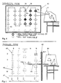
- Said store can be configured sequentially (figure 4) or in parallel mode (figure 5). In the sequential mode (figure 4), the system is slower because in order to select the chosen fabric 39 it is necessary to scroll through all the rolls of fabric up to the chosen one Pa.
- this system can still be effective, since the time required by the system to cut all the fabric is sufficient to allow a fresh roll of fabric to be present when it is required at the end of the current process.
- the system is instead very fast in any condition, even if a single item must be cut from each roll of fabric.
- the fabric access time of the parallel system is always the same, regardless of the position of the fabric inside the magazine i, j.
- the rolls of fabric are arranged in vertical columns, numbered 0 to N, which can move up or down. This movement allows to select the column from which the fabric roll is removed and place it in the upper position and to place all the other columns in the lower position. In this way, the fabric roll removal system can access, inside the store, only the fabric rolls that correspond to the elevated column. In this way, by means of a removal arm 46, it is possible to directly access the chosen roll without interfering with all the other rolls.
- This method allows to access any roll of any other column in the same manner, by selecting the column from which the roll is to be removed and placing it in the upper position while placing all the other columns into the lower position.
- the roll of fabric is removed by the movable arm 108 and by rotating about its fulcrum 109 it is moved into the position 110 which allows it to be deposited in the fabric unrolling/roll-up unit 112 in the position 111, from which the roll can begin to be unrolled onto the continuously moving transport surface such as a conveyor which has a variable controlled speed 103.
- Said moving conveyor is composed of three separate moving conveyors 103, 104, 105, all of which operate synchronously with each other except for the conveyor 103, which can be operated separately if the fabric is to be rolled up after a production run has ended.
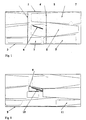
- the conveyor 103 is the one that takes up the fabric and stabilizes it with respect to the conveyance table by means of the control photocells 50, 51 with the aid of the unrolling/roll-up unit 49 which, being able to move transversely in both directions with respect to the fabric advancement direction, allows to correct the small variations that might occur during laying and are caused merely by the strength characteristics of the fabric to be laid.
- Said unrolling/roll-up unit by means of control and tensioning pulleys 54, 55, 56, 57, allows to keep the fabric under tension without deforming it, leaving the fibers that compose the fabric free from tension, and to send the fabric to the conveyor 58, 59 with a perfectly uniform speed.
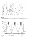
- the system conveys the fabric to the system for sensing the characteristics of the fabric (figure 8), which is composed of a set of linear video cameras 65 arranged so as to have a plurality of lightings 63, 62, 67 of the same line of fabric 66.
- the video cameras 65 are arranged along three sensing lines, depending on the type of lighting applied to the fabric, and specifically in the vertical case 63, in the parallel oblique case 62, and in the perpendicular oblique case 67. Comparison of these three or more sensing operations, if necessary, produces a highly precise indication, with an almost zero probability of error, of all the characteristics of the fabric and of its flaws, i.e., the characteristics that do not match the average description of said fabric.
- sensing operations do not occur with a single video camera but by aligning three video cameras (figure 9), wherein each video camera 68 senses a line a fabric over a length, termed sensing cone 70, which is equal to the need to achieve the chosen precision both in the fabric advancement direction and transversely thereto, which in the specific case can vary between 0.1 mm and 0.25 mm.
- the alignment of the video cameras 68 produces an overlap in the work areas of the resulting images, which must be filtered so as to eliminate this interference region by means of computational algorithms which allow to obtain a uniform image over the entire width of the fabric.
- Said line image is stored in the memory of the system in order to have a sequence of lines which is sufficient to perform a color analysis of the fabric. Depending on the sensed colors, which correspond to the different lightings performed, it is possible to obtain, by comparison, indications related to the geometry of the fabric and to any flaws that might be present internally.
- a very fast and complex computing system which is capable of handling, in real time, the depositing and optimization of the pieces to be cut, taking into account all the information concerning the fabric acquired in the previous step. Optimization is performed so as to comply with the characteristics of the item to be cut; all the parameters concerning the characteristics of the item are supplied by a model creation system CAD, to which the layout optimization system is connected in real time.
- the system must be connected not only to the system CAD but also to the system CED in order to receive in real time the number of items of that model to be produced, so as to lay them out along the entire length of the acquired fabric.
- All these operations are performed while the fabric is moving on the moving conveyor during the step between the acquisition of the fabric and the cutting system.
- the space between these two steps is constant and is a fixed parameter of the machine, while the time required to pass from one step to the next is variable and depends on the speed at which the conveyor is made to advance, so that if the fabric to be acquired or the item to be laid out is very complex, the system is capable of slowing the system in a fully automatic manner, so as to reach the cutting step exactly in time for the end of the computing of the optimum layout.
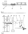
- the fabric arrives, again with a continuous cycle, at the cutting system (figure 10, figure 11), composed of a plurality of cutting heads 76 which are limited to two 82, 84 in the specific case for the sake of simplicity; each head operates on the entire cutting table asynchronously, and the heads are controlled by a computing system which optimizes the cutting path of both heads according to the path to be covered for each cutting head.
- the two cutting heads never collide and can both work on the same piece to be cut if necessary.
- Cutting is performed while the fabric is moving and the cutting heads work so as to take into account the advancement speed of the fabric on the moving conveyor, following the variations thereof caused by the preceding steps.
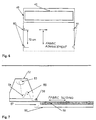
- the cutting system is composed of a suction system 83, which forces the layer of fabric to remain rested on the cutting table 80, which is composed of self-regenerating material or of a material which allows the blade 99 to penetrate to a thickness of no more than 4 millimeters.
- the suction table 83 operates exclusively on the moving conveyor, so that the fabric continues to adhere perfectly during the cutting step.
- the cutting heads are equipped with a blade-type cutting system which can be of the conventional type or a linear motor (figure 13), capable of producing very high cutting frequencies and with a very short vertical path of the cutting blade 99, measuring 1 or 2 millimeters.
- the two cutting heads work on the same cutting table and travel either on two separate sliders 75 or on the same slider, depending on whether movement occurs on the beam that supports the cutting heads (same slider) or is generated by a transmission generated at the level of the sliders by means of a belt drive or other equivalent mechanisms (two separate sliders).
- the cut fabric is sent to the system for removing said pieces (figure 12), so that said pieces are packaged to move on to the subsequent assembly step.
- Said packing system can operate in two modes which are controlled by a program that allows to collect the pieces in single-item mode or as a pack.
- all the pieces that compose an item are removed 89 by a removal system capable of adapting to the various geometries of the pieces 92, 93 and are deposited in a suitable container 88 which runs to the sides of the removal system and with the same speed as the moving conveyor, so that each container contains a complete item.
- a removal system capable of adapting to the various geometries of the pieces 92, 93 and are deposited in a suitable container 88 which runs to the sides of the removal system and with the same speed as the moving conveyor, so that each container contains a complete item.
- an automatic packing system binds together all the pieces that compose the item, so that it can be handled as a single unit and sent automatically to the subsequent processes.
Landscapes
- Engineering & Computer Science (AREA)
- Forests & Forestry (AREA)
- Mechanical Engineering (AREA)
- Life Sciences & Earth Sciences (AREA)
- General Engineering & Computer Science (AREA)
- Computer Vision & Pattern Recognition (AREA)
- Treatment Of Fiber Materials (AREA)
- Control And Other Processes For Unpacking Of Materials (AREA)
- Processing And Handling Of Plastics And Other Materials For Molding In General (AREA)
- Attitude Control For Articles On Conveyors (AREA)
- Tyre Moulding (AREA)
- Accessories And Tools For Shearing Machines (AREA)
- General Factory Administration (AREA)
- Separation, Recovery Or Treatment Of Waste Materials Containing Plastics (AREA)
- Management, Administration, Business Operations System, And Electronic Commerce (AREA)
Applications Claiming Priority (3)
| Application Number | Priority Date | Filing Date | Title |
|---|---|---|---|
| IT97VI000022A IT1298498B1 (it) | 1997-02-07 | 1997-02-07 | Metodo ed apparato per la stesura il taglio e il prelievo su conveyor in movimento a ciclo continuo, in automatico di parti componenti un |
| ITVI970022 | 1997-02-07 | ||
| PCT/EP1998/000534 WO1998034767A1 (en) | 1997-02-07 | 1998-02-02 | Method and apparatus for automatically laying, cutting and removing, on and from a continuously moving conveyor |
Publications (2)
| Publication Number | Publication Date |
|---|---|
| EP0958113A1 EP0958113A1 (en) | 1999-11-24 |
| EP0958113B1 true EP0958113B1 (en) | 2002-06-05 |
Family
ID=11426261
Family Applications (1)
| Application Number | Title | Priority Date | Filing Date |
|---|---|---|---|
| EP98905381A Expired - Lifetime EP0958113B1 (en) | 1997-02-07 | 1998-02-02 | Method and apparatus for automatically laying, cutting and removing, on and from a continuously moving conveyor |
Country Status (13)
| Country | Link |
|---|---|
| US (1) | US6349241B1 (it) |
| EP (1) | EP0958113B1 (it) |
| JP (1) | JP2001519723A (it) |
| AT (1) | ATE218418T1 (it) |
| AU (1) | AU6098698A (it) |
| CA (1) | CA2280616A1 (it) |
| DE (1) | DE69805754T2 (it) |
| DK (1) | DK0958113T3 (it) |
| ES (1) | ES2179452T3 (it) |
| IL (1) | IL131278A0 (it) |
| IT (1) | IT1298498B1 (it) |
| PT (1) | PT958113E (it) |
| WO (1) | WO1998034767A1 (it) |
Cited By (1)
| Publication number | Priority date | Publication date | Assignee | Title |
|---|---|---|---|---|
| EP4404010A1 (en) * | 2023-01-11 | 2024-07-24 | FBV-Electromits S.r.l. | Video inspection system of the fabric cutting operation |
Families Citing this family (26)
| Publication number | Priority date | Publication date | Assignee | Title |
|---|---|---|---|---|
| US6856843B1 (en) | 1998-09-09 | 2005-02-15 | Gerber Technology, Inc. | Method and apparatus for displaying an image of a sheet material and cutting parts from the sheet material |
| DE10013344A1 (de) * | 2000-03-17 | 2001-09-20 | Horst Kind Gmbh | Verfahren und Vorrichtung zum Führen eines Laserstrahls über ein Objekt |
| ITRN20000043A1 (it) * | 2000-10-26 | 2002-04-26 | Scm Group Spa | Macchina utensile per la lavorazione del legno con sistema computazionale integrato |
| GB0027076D0 (en) * | 2000-11-06 | 2000-12-20 | Stern Ivan | Location and identification systems |
| DE10205562C1 (de) * | 2002-02-11 | 2003-07-31 | Gerber Technology Inc | Verfahren und Vorrichtung zum Anzeigen eines Abbildes eines Flachmaterials und zum Ausschneiden von Teilen aus dem Flachmaterial |
| US6879873B2 (en) * | 2002-04-10 | 2005-04-12 | Billco Manufacturing Inc. | CNC glass cutting line with dynamic continuous production control system |
| ITVI20030210A1 (it) * | 2003-10-28 | 2005-04-29 | Cos T A Srl | Metodo per rifilare e/o misurare in continuo un elemento |
| US20060080820A1 (en) * | 2004-10-18 | 2006-04-20 | Belote Adam T | Method and apparatus for a reducing surface area profile required for a gasket part cut from a sheet of gasket material |
| US8359116B2 (en) * | 2009-09-11 | 2013-01-22 | Sap Ag | Production management system |
| EP2590040B1 (en) * | 2011-11-04 | 2014-05-28 | Nivora IP B.V. | Method and device for aiding in manual handling of a work piece during machining |
| US10552551B2 (en) | 2011-11-18 | 2020-02-04 | Nike, Inc. | Generation of tool paths for shore assembly |
| US8849620B2 (en) | 2011-11-18 | 2014-09-30 | Nike, Inc. | Automated 3-D modeling of shoe parts |
| US8755925B2 (en) * | 2011-11-18 | 2014-06-17 | Nike, Inc. | Automated identification and assembly of shoe parts |
| US10579049B2 (en) * | 2014-09-08 | 2020-03-03 | The Boeing Company | Automatic material cutting system |
| JP6456274B2 (ja) * | 2015-12-11 | 2019-01-23 | 株式会社島精機製作所 | 延反システム及び延反方法 |
| US9782906B1 (en) * | 2015-12-16 | 2017-10-10 | Amazon Technologies, Inc. | On demand apparel panel cutting |
| US9623578B1 (en) * | 2015-12-16 | 2017-04-18 | Amazon Technologies, Inc. | On demand apparel manufacturing |
| US10820649B2 (en) | 2016-03-14 | 2020-11-03 | Amazon Technologies, Inc. | Organized assembly instruction printing and referencing |
| US9895819B1 (en) | 2016-03-14 | 2018-02-20 | Amazon Technologies, Inc. | Continuous feed fabric cutting |
| US10307926B2 (en) | 2016-03-14 | 2019-06-04 | Amazon Technologies, Inc. | Automated fabric picking |
| US9868302B1 (en) | 2016-06-20 | 2018-01-16 | Amazon Technologies, Inc. | Fluorescent ink printing, cutting, and apparel assembly |
| CN109676656B (zh) * | 2019-01-31 | 2023-09-12 | 无锡蓝智自动化科技有限公司 | 安全带超声波切断装置 |
| DE102019107586B4 (de) * | 2019-03-25 | 2023-03-30 | Held Systems Gmbh | Abnahmevorrichtung zum automatisierten Abnehmen von Gewebematerialteilen, ein Verfahren zum automatisierten Abnehmen von Gewebematerialteilen und eine Produktionsanlage mit einer Fördereinrichtung und einer Abnahmevorrichtung |
| KR102052193B1 (ko) * | 2019-07-16 | 2020-01-08 | 신상용 | 사무용 의자 제조장치 및 이를 이용하는 사무용 의자 제조방법 |
| CN112450637B (zh) * | 2020-11-06 | 2022-04-29 | 安徽情暖家具有限公司 | 一种高弹性沙发生产设备 |
| SE548442C2 (en) * | 2023-06-13 | 2026-08-06 | Beskow von Post AB | An upcycling method and system for use of fabric from clothes |
Family Cites Families (6)
| Publication number | Priority date | Publication date | Assignee | Title |
|---|---|---|---|---|
| DE8108075U1 (de) | 1981-03-19 | 1981-10-08 | Stumpf, Günter O., 7432 Urach | Bewegliches fuehrungssystem fuer zuschneidemaschine |
| IT1234568B (it) * | 1988-06-07 | 1992-05-20 | Necchi Spa | Macchina per l'alimentazione e la cucitura di strati di tessuto sovrapposti |
| EP0387371B1 (de) | 1989-03-14 | 1994-07-27 | Wolf Dieter Merz | Verfahren und Vorrichtung zum Zuschneiden von Schnitteilen für Bekleidungsstücke |
| US5172326A (en) * | 1990-03-19 | 1992-12-15 | Forcam, Incorporated | Patterned web cutting method and system for operation manipulation of displayed nested templates relative to a displayed image of a patterned web |
| DE4012462A1 (de) | 1990-04-19 | 1991-10-24 | Duerkopp System Technik Gmbh | Verfahren zum nesten von naturleder |
| AT406464B (de) * | 1997-08-21 | 2000-05-25 | Gfm Holding Ag | Verfahren zum erstellen eines schnittnestes |
-
1997
- 1997-02-07 IT IT97VI000022A patent/IT1298498B1/it active IP Right Grant
-
1998
- 1998-02-02 AU AU60986/98A patent/AU6098698A/en not_active Abandoned
- 1998-02-02 PT PT98905381T patent/PT958113E/pt unknown
- 1998-02-02 US US09/355,557 patent/US6349241B1/en not_active Expired - Fee Related
- 1998-02-02 DE DE69805754T patent/DE69805754T2/de not_active Expired - Fee Related
- 1998-02-02 DK DK98905381T patent/DK0958113T3/da active
- 1998-02-02 CA CA002280616A patent/CA2280616A1/en not_active Abandoned
- 1998-02-02 JP JP53373198A patent/JP2001519723A/ja active Pending
- 1998-02-02 AT AT98905381T patent/ATE218418T1/de not_active IP Right Cessation
- 1998-02-02 WO PCT/EP1998/000534 patent/WO1998034767A1/en not_active Ceased
- 1998-02-02 ES ES98905381T patent/ES2179452T3/es not_active Expired - Lifetime
- 1998-02-02 IL IL13127898A patent/IL131278A0/xx unknown
- 1998-02-02 EP EP98905381A patent/EP0958113B1/en not_active Expired - Lifetime
Cited By (2)
| Publication number | Priority date | Publication date | Assignee | Title |
|---|---|---|---|---|
| EP4404010A1 (en) * | 2023-01-11 | 2024-07-24 | FBV-Electromits S.r.l. | Video inspection system of the fabric cutting operation |
| WO2024149866A3 (en) * | 2023-01-11 | 2024-08-29 | Fbv-Electromits Srl | Video inspection system of a fabric cutting operation |
Also Published As
| Publication number | Publication date |
|---|---|
| IL131278A0 (en) | 2001-01-28 |
| AU6098698A (en) | 1998-08-26 |
| ITVI970022A1 (it) | 1998-08-07 |
| EP0958113A1 (en) | 1999-11-24 |
| US6349241B1 (en) | 2002-02-19 |
| ES2179452T3 (es) | 2003-01-16 |
| PT958113E (pt) | 2002-10-31 |
| IT1298498B1 (it) | 2000-01-10 |
| DE69805754T2 (de) | 2002-09-19 |
| JP2001519723A (ja) | 2001-10-23 |
| CA2280616A1 (en) | 1998-08-13 |
| DE69805754D1 (de) | 2002-07-11 |
| ATE218418T1 (de) | 2002-06-15 |
| DK0958113T3 (da) | 2002-07-01 |
| WO1998034767A1 (en) | 1998-08-13 |
Similar Documents
| Publication | Publication Date | Title |
|---|---|---|
| US6349241B1 (en) | Method and apparatus for automatically laying, cutting and removing material on and from a continuously moving conveyor | |
| US4328726A (en) | Apparatus and method for working on successive segments of sheet material | |
| EP1810816B1 (en) | Visual fiber placement inspection | |
| EP0230137A1 (en) | Horizontal form-fill-seal packaging machines | |
| US4972745A (en) | Method and apparatus for cutting blanks from webs of material | |
| US5603270A (en) | Quilting material handling and feeding method and apparatus | |
| KR20180088716A (ko) | 롤 형태로 감긴 재료의 텐셔닝 및 로딩 시스템 | |
| EP1294556B1 (en) | Method and plant for manufacturing a belt structure of a green tire. | |
| JP2005513642A (ja) | シート材料の連続流において予め設定された形状を切断するためのシステム | |
| EP0448407A2 (en) | Method of manufacturing tires with different sizes in hybrid manner | |
| KR19980702728A (ko) | 내부 코일 스프링 조립방법 및 장치 | |
| US3742878A (en) | Control for sewing machine | |
| US4588871A (en) | Fabric cutting apparatus and method | |
| RU2331519C2 (ru) | Устройство, агрегат и способ для изготовления брекерного слоя шины | |
| EP0568761B1 (en) | Tape cassette feed unit for automatic machines | |
| US20230330880A1 (en) | Method and system for automatic cutting of pieces in a flexible material packaged in roll form | |
| JP7864138B2 (ja) | ウェブ製品のリール形状を制御する装置 | |
| EP3578710B1 (en) | Apparatus and method for continuous detection and cutting of fabric for items of clothing | |
| ITFI20000036A1 (it) | Apparecchiatura per la rifilatura automatica di suole in materiale plastico per calzature e relativo metodo di rifilatura | |
| US4285258A (en) | Device for translating and rotating a cutting platen with respect to a reciprocal cutter | |
| US4323149A (en) | Transfer apparatus for natural tobacco leaves | |
| CN214149129U (zh) | 三角厚度检测装置 | |
| EP0020003A2 (en) | Method and device for cutting and transferring a contoured tobacco sheet profile | |
| CA1138719A (en) | Apparatus and method for working on successive segments of sheet material | |
| US4339974A (en) | Supporting anvil for movable cutting platen |
Legal Events
| Date | Code | Title | Description |
|---|---|---|---|
| PUAI | Public reference made under article 153(3) epc to a published international application that has entered the european phase |
Free format text: ORIGINAL CODE: 0009012 |
|
| 17P | Request for examination filed |
Effective date: 19990729 |
|
| AK | Designated contracting states |
Kind code of ref document: A1 Designated state(s): AT BE CH DE DK ES FI FR GB GR IE IT LI LU NL PT SE |
|
| 17Q | First examination report despatched |
Effective date: 20000815 |
|
| GRAG | Despatch of communication of intention to grant |
Free format text: ORIGINAL CODE: EPIDOS AGRA |
|
| GRAG | Despatch of communication of intention to grant |
Free format text: ORIGINAL CODE: EPIDOS AGRA |
|
| GRAH | Despatch of communication of intention to grant a patent |
Free format text: ORIGINAL CODE: EPIDOS IGRA |
|
| RAP1 | Party data changed (applicant data changed or rights of an application transferred) |
Owner name: PERON, ALBERTO |
|
| RIN1 | Information on inventor provided before grant (corrected) |
Inventor name: PERON, ALBERTO |
|
| GRAH | Despatch of communication of intention to grant a patent |
Free format text: ORIGINAL CODE: EPIDOS IGRA |
|
| GRAA | (expected) grant |
Free format text: ORIGINAL CODE: 0009210 |
|
| AK | Designated contracting states |
Kind code of ref document: B1 Designated state(s): AT BE CH DE DK ES FI FR GB GR IE IT LI LU NL PT SE |
|
| REF | Corresponds to: |
Ref document number: 218418 Country of ref document: AT Date of ref document: 20020615 Kind code of ref document: T |
|
| REG | Reference to a national code |
Ref country code: GB Ref legal event code: FG4D |
|
| REG | Reference to a national code |
Ref country code: CH Ref legal event code: NV Representative=s name: ROTTMANN, ZIMMERMANN + PARTNER AG Ref country code: CH Ref legal event code: EP |
|
| REG | Reference to a national code |
Ref country code: DK Ref legal event code: T3 |
|
| REG | Reference to a national code |
Ref country code: IE Ref legal event code: FG4D |
|
| REF | Corresponds to: |
Ref document number: 69805754 Country of ref document: DE Date of ref document: 20020711 |
|
| REG | Reference to a national code |
Ref country code: GR Ref legal event code: EP Ref document number: 20020402531 Country of ref document: GR |
|
| ET | Fr: translation filed | ||
| REG | Reference to a national code |
Ref country code: PT Ref legal event code: SC4A Free format text: AVAILABILITY OF NATIONAL TRANSLATION Effective date: 20020813 |
|
| REG | Reference to a national code |
Ref country code: ES Ref legal event code: FG2A Ref document number: 2179452 Country of ref document: ES Kind code of ref document: T3 |
|
| PGFP | Annual fee paid to national office [announced via postgrant information from national office to epo] |
Ref country code: GB Payment date: 20030204 Year of fee payment: 6 |
|
| PGFP | Annual fee paid to national office [announced via postgrant information from national office to epo] |
Ref country code: FI Payment date: 20030205 Year of fee payment: 6 |
|
| PGFP | Annual fee paid to national office [announced via postgrant information from national office to epo] |
Ref country code: GR Payment date: 20030207 Year of fee payment: 6 Ref country code: IE Payment date: 20030207 Year of fee payment: 6 |
|
| PGFP | Annual fee paid to national office [announced via postgrant information from national office to epo] |
Ref country code: PT Payment date: 20030211 Year of fee payment: 6 Ref country code: CH Payment date: 20030211 Year of fee payment: 6 Ref country code: AT Payment date: 20030211 Year of fee payment: 6 |
|
| PGFP | Annual fee paid to national office [announced via postgrant information from national office to epo] |
Ref country code: ES Payment date: 20030212 Year of fee payment: 6 |
|
| PGFP | Annual fee paid to national office [announced via postgrant information from national office to epo] |
Ref country code: SE Payment date: 20030213 Year of fee payment: 6 |
|
| PGFP | Annual fee paid to national office [announced via postgrant information from national office to epo] |
Ref country code: DK Payment date: 20030214 Year of fee payment: 6 |
|
| PGFP | Annual fee paid to national office [announced via postgrant information from national office to epo] |
Ref country code: FR Payment date: 20030217 Year of fee payment: 6 |
|
| PGFP | Annual fee paid to national office [announced via postgrant information from national office to epo] |
Ref country code: BE Payment date: 20030218 Year of fee payment: 6 |
|
| PGFP | Annual fee paid to national office [announced via postgrant information from national office to epo] |
Ref country code: LU Payment date: 20030220 Year of fee payment: 6 |
|
| PGFP | Annual fee paid to national office [announced via postgrant information from national office to epo] |
Ref country code: NL Payment date: 20030221 Year of fee payment: 6 |
|
| PGFP | Annual fee paid to national office [announced via postgrant information from national office to epo] |
Ref country code: DE Payment date: 20030306 Year of fee payment: 6 |
|
| PLBE | No opposition filed within time limit |
Free format text: ORIGINAL CODE: 0009261 |
|
| STAA | Information on the status of an ep patent application or granted ep patent |
Free format text: STATUS: NO OPPOSITION FILED WITHIN TIME LIMIT |
|
| 26N | No opposition filed |
Effective date: 20030306 |
|
| PG25 | Lapsed in a contracting state [announced via postgrant information from national office to epo] |
Ref country code: LU Free format text: LAPSE BECAUSE OF NON-PAYMENT OF DUE FEES Effective date: 20040202 Ref country code: IE Free format text: LAPSE BECAUSE OF NON-PAYMENT OF DUE FEES Effective date: 20040202 Ref country code: GB Free format text: LAPSE BECAUSE OF NON-PAYMENT OF DUE FEES Effective date: 20040202 Ref country code: FI Free format text: LAPSE BECAUSE OF NON-PAYMENT OF DUE FEES Effective date: 20040202 Ref country code: AT Free format text: LAPSE BECAUSE OF NON-PAYMENT OF DUE FEES Effective date: 20040202 |
|
| PG25 | Lapsed in a contracting state [announced via postgrant information from national office to epo] |
Ref country code: SE Free format text: LAPSE BECAUSE OF NON-PAYMENT OF DUE FEES Effective date: 20040203 Ref country code: ES Free format text: LAPSE BECAUSE OF NON-PAYMENT OF DUE FEES Effective date: 20040203 |
|
| PG25 | Lapsed in a contracting state [announced via postgrant information from national office to epo] |
Ref country code: BE Free format text: LAPSE BECAUSE OF NON-PAYMENT OF DUE FEES Effective date: 20040228 |
|
| PG25 | Lapsed in a contracting state [announced via postgrant information from national office to epo] |
Ref country code: LI Free format text: LAPSE BECAUSE OF NON-PAYMENT OF DUE FEES Effective date: 20040229 Ref country code: CH Free format text: LAPSE BECAUSE OF NON-PAYMENT OF DUE FEES Effective date: 20040229 |
|
| PG25 | Lapsed in a contracting state [announced via postgrant information from national office to epo] |
Ref country code: DK Free format text: LAPSE BECAUSE OF NON-PAYMENT OF DUE FEES Effective date: 20040301 |
|
| BERE | Be: lapsed |
Owner name: *PERON ALBERTO Effective date: 20040228 |
|
| PG25 | Lapsed in a contracting state [announced via postgrant information from national office to epo] |
Ref country code: PT Free format text: LAPSE BECAUSE OF NON-PAYMENT OF DUE FEES Effective date: 20040831 |
|
| PG25 | Lapsed in a contracting state [announced via postgrant information from national office to epo] |
Ref country code: NL Free format text: LAPSE BECAUSE OF NON-PAYMENT OF DUE FEES Effective date: 20040901 Ref country code: DE Free format text: LAPSE BECAUSE OF NON-PAYMENT OF DUE FEES Effective date: 20040901 |
|
| PG25 | Lapsed in a contracting state [announced via postgrant information from national office to epo] |
Ref country code: GR Free format text: LAPSE BECAUSE OF NON-PAYMENT OF DUE FEES Effective date: 20040903 |
|
| GBPC | Gb: european patent ceased through non-payment of renewal fee |
Effective date: 20040202 |
|
| REG | Reference to a national code |
Ref country code: DK Ref legal event code: EBP |
|
| EUG | Se: european patent has lapsed | ||
| REG | Reference to a national code |
Ref country code: CH Ref legal event code: PL |
|
| PG25 | Lapsed in a contracting state [announced via postgrant information from national office to epo] |
Ref country code: FR Free format text: LAPSE BECAUSE OF NON-PAYMENT OF DUE FEES Effective date: 20041029 |
|
| NLV4 | Nl: lapsed or anulled due to non-payment of the annual fee |
Effective date: 20040901 |
|
| REG | Reference to a national code |
Ref country code: IE Ref legal event code: MM4A |
|
| REG | Reference to a national code |
Ref country code: FR Ref legal event code: ST |
|
| PG25 | Lapsed in a contracting state [announced via postgrant information from national office to epo] |
Ref country code: IT Free format text: LAPSE BECAUSE OF NON-PAYMENT OF DUE FEES;WARNING: LAPSES OF ITALIAN PATENTS WITH EFFECTIVE DATE BEFORE 2007 MAY HAVE OCCURRED AT ANY TIME BEFORE 2007. THE CORRECT EFFECTIVE DATE MAY BE DIFFERENT FROM THE ONE RECORDED. Effective date: 20050202 |
|
| REG | Reference to a national code |
Ref country code: ES Ref legal event code: FD2A Effective date: 20040203 |