EP0958731B1 - Appareil à déplacer des végétaux se trouvant sur le sol - Google Patents
Appareil à déplacer des végétaux se trouvant sur le sol Download PDFInfo
- Publication number
- EP0958731B1 EP0958731B1 EP19990201435 EP99201435A EP0958731B1 EP 0958731 B1 EP0958731 B1 EP 0958731B1 EP 19990201435 EP19990201435 EP 19990201435 EP 99201435 A EP99201435 A EP 99201435A EP 0958731 B1 EP0958731 B1 EP 0958731B1
- Authority
- EP
- European Patent Office
- Prior art keywords
- rake members
- implement
- group
- rake
- travel
- Prior art date
- Legal status (The legal status is an assumption and is not a legal conclusion. Google has not performed a legal analysis and makes no representation as to the accuracy of the status listed.)
- Expired - Lifetime
Links
Images
Classifications
-
- A—HUMAN NECESSITIES
- A01—AGRICULTURE; FORESTRY; ANIMAL HUSBANDRY; HUNTING; TRAPPING; FISHING
- A01D—HARVESTING; MOWING
- A01D78/00—Haymakers with tines moving with respect to the machine
- A01D78/08—Haymakers with tines moving with respect to the machine with tine-carrying rotary heads or wheels
- A01D78/10—Haymakers with tines moving with respect to the machine with tine-carrying rotary heads or wheels the tines rotating about a substantially vertical axis
- A01D78/1085—Having two rows of rotors on two different horizontal lines perpendicular to the advance direction of the machine
Definitions
- the invention relates to an implement for laterally displacing crop lying on the soil according to the preamble of claim 1.
- a transverse carrier comprises a central pair of rake members indicated as a first group of rake members.
- the transverse carrier has at each end a vertical pivot for an extension arm.
- the rake members of the second group are mounted.
- the implement can be arranged such that the rake members of the first group are orientated along each other and in front of the two outer rake members.
- the right hand rake members can be rotated clockwise while the left hand rake members rotate anticlockwise such that at either side of the implement a swath is formed.
- the extension arms can be pivoted relatively to the transverse carrier about the vertical pivot axes such that the width of implement is reduced.
- a hay making machine is described with a leading central group of two rake members and a second group of rake members comprising two lateral pairs, which pairs are arranged rearwardly and laterally offset to the central pair.
- the direction of rotation of each pair is individually variable.
- the rake members of the leading group rotate such that in plan view the rake member on the right hand side rotates clockwise and the rake member on the left hand side rotates anticlockwise, while the rake members of a lateral pair rotate in opposite directions and such that the outer rake member of the right hand repair rotates anticlockwise and the outer rake member of the left hand pair rotates clockwise.
- Two swaths are formed between the rake members of the lateral pairs, however not at the two outer lateral sides of the implement, so that not the maximum working width of the implement is used for swathing.
- a hay making machine is described with a group of two large rake members placed along each other. Both rake members are driven in opposite directions such that seen in plan view the rake member at the right hand side is driven anticlockwise. The crop is raked from the outside to the inside, in such a manner that in the centre of the implement a swath is formed.
- a group of two smaller rake members is provided in front of this zone which rake members rotate in opposite directions.
- the small rake member, seen in the direction of travel, located on the right hand rotates clockwise. For being brought into the transport position all rake members are pivotable upwardly about axes orientated in the direction of travel.
- two groups of running wheels are disposed between the rake members, the distance between the outer lateral sides of the running wheels being smaller than the distance between the outer lateral sides of the paths described by the tines of the outer rake members of the leading group. In this manner a proper and balanced support of the implement can be obtained.
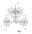
- Figure 1 is a plan view of the implement.
- the implement according to the invention is provided with a frame beam 1 extending in the direction of travel A and capable of being coupled at its front side to a tractor.
- each of these frame beams 2 and 3 carries at its free end a rake member 4, 5 respectively rotating about an upwardly orientated axis.
- the rake members are provided with gearboxes 6, 7 respectively whose drive is coupled with a transmission box 8 disposed on the frame beam 1 via intermediate shafts that are preferably located in the frame beams 2 and 3.
- the drive of the rake members 4 and 5 is such that the rake member 4 rotates anticlockwise and the rake member 5 rotates clockwise.
- the distance between the axes of rotation of the rake members 4 and 5 is such that, in plan view, the outer tine paths 9, 10 respectively are close to each other and preferably are tangential or intersect.
- the tines of one rake member should be arranged relative to the tines of the other rake member so as not to come into contact with each other when rotating.
- the implement further comprises a second group of rake members 11, 12 respectively which, seen in the direction of travel, are fitted behind the first group of rake members to a frame beam 13, 14 respectively disposed transversely to the direction of travel.
- these rake members are each driven about an upwardly orientated shaft. (These rake members are designed in a manner known per se; the Lely Hibiscus can be mentioned as an example thereof.)
- the frame beams 13, 14 respectively are fastened to the frame beam 1.
- a gearbox 15, 16 respectively via which the rake members 11, 12 respectively are each driven by means of intermediate shafts, located in the frame beams 13, 14 respectively, and a centrally located transmission box 17.
- the direction of rotation of the rake member 11 corresponds to that of the rake member 4 and the direction of rotation of the rake member 12 corresponds to that of the rake member 5.
- the distance between the rake members 11 and 12 is such that, seen in the direction of travel A, the outermost left-hand part of the left-hand side of the tine path 9 of the rake member 4 overlaps the outermost right-hand part of the right-hand side of the tine path 18 of the rake member 11.
- the outermost right-hand part of the tine path 10 of the rake member 5 overlaps the outermost left-hand part of the tine path 19 of the rake member 12.
- the transmission box 17 is coupled with the transmission box 8 which can be coupled itself, via one or more intermediate shafts, with the non-shown drive shaft of the tractor.
- the rake members 4, 5 respectively have less tine arms 22, eleven in this embodiment, than the rake members 11, 12 respectively, which are each provided with thirteen tine arms 23 in this embodiment.
- each tine arm two downwardly extending tines are fastened in a manner known per se.
- the running wheels 24 are preferably located in or near the centre of gravity of the implement.
- the implement operates as follows.
- the machine functions as a rake and the rake members 4 and 5 displace the mown crop (usually grass) lying on the soil to the left, to the right respectively, so that on the left-hand side, on the right-hand side respectively of the group of rake members 4 and 5 there is created a swath 25, 26 respectively.
- these swaths 25, 26 respectively are located before the rake members 11, 12 respectively which, as a result thereof, displace the crop lying before the rake members together with the swath to the left, to the right respectively, so that eventually both on the left-hand side and the right-hand side of the implement there is created a large swath 27, 28 respectively.
- the rake members 11, 12 respectively have to displace more crop than the rake members 4, 5 respectively and for that reason have more tine arms provided with tines than the rake members 4, 5 respectively.
- each of the running wheels 24 of the frame beam 1 is such that the running wheels, seen in the direction of travel A, move on the raked soil and are consequently located between the swaths 25 and 26.
- the distance measured between the swaths 27 and 28 transversely to the direction of travel A may amount to approximately 15 m when the machine is provided with normal rake members having a diameter of approximately 3.60 m.
- the first group of rake members 29, 30 can be pivoted upwards about pivotal axes 29, 30 orientated in the direction of travel A.
- the rake members 11, 12 respectively can be pivoted upwards about axes 31 and 32 orientated in the direction of travel A.
- the rake members rotate in such a manner that a swath is formed on the left-hand side, the right-hand side respectively of the rake members 11, 12 respectively.
- the invention also relates to an implement in which the rake members have an opposite direction of rotation, so that a swath is created in the centre of the implement.
Landscapes
- Life Sciences & Earth Sciences (AREA)
- Environmental Sciences (AREA)
- Soil Working Implements (AREA)
Claims (10)
- Appareil pour déplacer latéralement des végétaux se trouvant sur le sol, lequel appareil comprend des éléments de râteau (4, 5, 11, 12) qui sont entraínés de manière à pouvoir tourner le long d'axes orientés vers le haut, lesquels éléments de râteau, représentés dans la direction du déplacement, sont agencés dans au moins deux groupes d'au moins deux éléments de râteau, lesdits groupes étant disposés l'un derrière l'autre, les éléments de râteau externes de chaque groupe effectuant une rotation dans des directions opposées, la distance entre les axes de rotation des éléments de râteau externes (4, 5) du groupe avant étant inférieure à la distance entre les axes de rotation des éléments de râteau externes (11, 12) du groupe des éléments de râteau disposés derrière et les directions de rotation des éléments de râteau externes (4, 5, 11, 12) de chaque groupe étant opposées les unes aux autres d'une manière telle qu'en vue en plan les éléments de râteau externes (4, 11) qui, représentés dans la direction du déplacement, sont situés du côté gauche de l'appareil, effectuent une rotation dans le sens contraire des aiguilles d'une montre et que les éléments de râteau externes (5, 12) qui, représentés dans la direction du déplacement, sont situés du côté droit, effectuent une rotation dans le sens des aiguilles d'une montre, caractérisés en ce que, afin d'être amenés en position de transport, les éléments de râteau (4, 5, 11, 12) sont pliables vers le haut le long d'axes de pivotement (29, 30, 31, 32) orientés dans la direction du déplacement.
- Appareil selon la revendication 1, caractérisé en ce que, représentés dans la direction du déplacement, deux groupes de roues courantes (24) sont agencés entre les éléments de râteau (4, 5, 11, 12), la distance entre les côtés latéraux externes des roues de roulement (24) étant inférieure à la distance entre les côtés latéraux externes des trajets décrits par les dents des éléments de râteau externes (4, 5) du groupe avant.
- Appareil selon l'une quelconque des revendications précédentes, caractérisé en ce que les éléments de râteau (4, 5) d'un groupe ont un nombre de bras porte-dents différent de celui des éléments de râteau (11, 12) de l'autre groupe.
- Appareil selon la revendication 3, caractérisé en ce que les éléments de râteau (4, 5) du groupe avant ont moins de bras porte-dents que les éléments de râteau (11, 12) du groupe arrière.
- Appareil selon la revendication 4, caractérisé en ce que les éléments de râteau (4, 5) du groupe avant ont chacun onze bras porte-dents et les éléments de râteau (11, 12) du groupe disposé derrière ont chacun treize bras porte-dents.
- Appareil selon l'une quelconque des revendications précédentes, caractérisé en ce que chacun des éléments de râteau externes (4, 5) du groupe avant ratisse les végétaux latéralement en un andain qui, représenté dans la direction du déplacement, sera situé devant l'élément de râteau (11, 12) agencé sur le côté latéral externe d'un groupe disposé derrière.
- Appareil selon l'une quelconque des revendications 2 à 6, caractérisé en ce que les roues de roulement (24) sont situées entre les andains créés par les éléments de râteau externes du groupe avant des éléments de râteau (4, 5).
- Appareil selon l'une quelconque des revendications précédentes, caractérisé en ce que l'appareil est équipé d'une poutre de châssis (1) s'étendant sensiblement dans la direction du déplacement.
- Appareil selon la revendication 8, caractérisé en ce que les éléments de râteau de chaque groupe sont ajustés à une poutre de châssis (2, 3, 13, 14) s'étendant transversalement vers la direction du déplacement de l'appareil, dont la poutre de châssis est ajustée à la poutre de châssis (1) s'étendant dans la direction du déplacement.
- Appareil selon l'une quelconque des revendications précédentes, caractérisé en ce que chaque élément de râteau peut être pivoté vers le haut le long d'un axe de pivotement séparé afin d'être amené en position de transport.
Applications Claiming Priority (2)
| Application Number | Priority Date | Filing Date | Title |
|---|---|---|---|
| NL1009224 | 1998-05-20 | ||
| NL1009224A NL1009224C2 (nl) | 1998-05-20 | 1998-05-20 | Inrichting voor het zijwaarts verplaatsen van op de grond liggend gewas. |
Publications (2)
| Publication Number | Publication Date |
|---|---|
| EP0958731A1 EP0958731A1 (fr) | 1999-11-24 |
| EP0958731B1 true EP0958731B1 (fr) | 2003-03-26 |
Family
ID=19767178
Family Applications (1)
| Application Number | Title | Priority Date | Filing Date |
|---|---|---|---|
| EP19990201435 Expired - Lifetime EP0958731B1 (fr) | 1998-05-20 | 1999-05-07 | Appareil à déplacer des végétaux se trouvant sur le sol |
Country Status (3)
| Country | Link |
|---|---|
| EP (1) | EP0958731B1 (fr) |
| DE (1) | DE69906183T2 (fr) |
| NL (1) | NL1009224C2 (fr) |
Families Citing this family (1)
| Publication number | Priority date | Publication date | Assignee | Title |
|---|---|---|---|---|
| DE10327883B4 (de) * | 2003-06-20 | 2006-01-05 | Maschinenfabrik Bernard Krone Gmbh | Heuwerbungsmaschine |
Family Cites Families (7)
| Publication number | Priority date | Publication date | Assignee | Title |
|---|---|---|---|---|
| NL127731C (fr) * | 1959-10-23 | |||
| DE1229770B (de) * | 1962-10-17 | 1966-12-01 | Fahr Ag Maschf | Heuwerbungsmaschine |
| DE2828282A1 (de) * | 1978-06-28 | 1980-01-10 | Kloeckner Humboldt Deutz Ag | Heuwerbungsmaschine zum seitlichen zusammenrechen von auf dem boden liegendem erntegut |
| FR2663189B1 (fr) * | 1990-06-14 | 1994-03-18 | Kuhn Sa | Machine de fenaison pour l'andainage, comportant au moins deux roues rateleuses. |
| DE9014438U1 (de) * | 1990-10-18 | 1991-02-14 | H. Niemeyer Söhne GmbH & Co KG, 4446 Hörstel | Heuwerbungsmaschine |
| HU223063B1 (hu) | 1996-07-16 | 2004-03-01 | Claas Saulgau Gmbh. | Pörgettyűs rendrakó |
| DE29716391U1 (de) * | 1997-09-12 | 1997-11-06 | Maschinenfabriken Bernard Krone Gmbh, 48480 Spelle | Heuwerbungsmaschine |
-
1998
- 1998-05-20 NL NL1009224A patent/NL1009224C2/nl active Search and Examination
-
1999
- 1999-05-07 EP EP19990201435 patent/EP0958731B1/fr not_active Expired - Lifetime
- 1999-05-07 DE DE1999606183 patent/DE69906183T2/de not_active Expired - Lifetime
Also Published As
| Publication number | Publication date |
|---|---|
| DE69906183T2 (de) | 2004-01-29 |
| DE69906183D1 (de) | 2003-04-30 |
| NL1009224C2 (nl) | 1999-11-24 |
| EP0958731A1 (fr) | 1999-11-24 |
Similar Documents
| Publication | Publication Date | Title |
|---|---|---|
| EP0844814B1 (fr) | Machine pour la fenaison | |
| US6907719B2 (en) | Agricultural implement comprising a transporting device | |
| US6164051A (en) | Machine combination, a rake and pick-up and displacing member, as well as a method | |
| US6421994B1 (en) | Mowing implement | |
| EP0848900B1 (fr) | Machine de fenaison | |
| US5862659A (en) | Haymaking machine with at least one windrowing rotor | |
| EP0715804B1 (fr) | Machine pour traiter une récolte disposée sur le sol | |
| EP0558437A1 (fr) | Faucheuse de végétaux | |
| EP0524668B1 (fr) | Machine pour le traitement de végétaux à tiges | |
| EP0958731B1 (fr) | Appareil à déplacer des végétaux se trouvant sur le sol | |
| ATE154866T1 (de) | Heuwerbungsmaschine | |
| US4263774A (en) | Haymaking machine | |
| US4148176A (en) | Hay making machine | |
| EP0978228A1 (fr) | Dispositif pour déplacer des végétaux se trouvant sur le sol | |
| EP0903067A2 (fr) | Appareil pliable pour traiter de la récolte couchée sur terre | |
| EP0507408B2 (fr) | Machine agricole | |
| EP1668977A2 (fr) | Machine de fenaison | |
| AU740416B2 (en) | A foldable agricultural machine, as well as a method of folding same from the working position into the transport position | |
| EP0887010B1 (fr) | Dispositif de réglage d'une machine agricole telle qu'une machine de fenaison | |
| US20020000083A1 (en) | Implement for displacing crop, such as grass or hay for example | |
| AU741684B2 (en) | An implement for displacing crop lying on the soil | |
| EP0147895B1 (fr) | Appareil pour le râtelage | |
| EP0258925A1 (fr) | Machine pour travailler la récolte | |
| EP0257697A1 (fr) | Machine pour le conditionnement de produits de récolte | |
| EP0876751A1 (fr) | Dispositif pour déplacer des végétaux se trouvant sur le sol |
Legal Events
| Date | Code | Title | Description |
|---|---|---|---|
| PUAI | Public reference made under article 153(3) epc to a published international application that has entered the european phase |
Free format text: ORIGINAL CODE: 0009012 |
|
| AK | Designated contracting states |
Kind code of ref document: A1 Designated state(s): DE FR GB NL |
|
| AX | Request for extension of the european patent |
Free format text: AL;LT;LV;MK;RO;SI |
|
| 17P | Request for examination filed |
Effective date: 20000331 |
|
| AKX | Designation fees paid |
Free format text: DE FR GB NL |
|
| 17Q | First examination report despatched |
Effective date: 20020328 |
|
| GRAH | Despatch of communication of intention to grant a patent |
Free format text: ORIGINAL CODE: EPIDOS IGRA |
|
| GRAH | Despatch of communication of intention to grant a patent |
Free format text: ORIGINAL CODE: EPIDOS IGRA |
|
| GRAA | (expected) grant |
Free format text: ORIGINAL CODE: 0009210 |
|
| AK | Designated contracting states |
Designated state(s): DE FR GB NL |
|
| REG | Reference to a national code |
Ref country code: GB Ref legal event code: FG4D |
|
| REF | Corresponds to: |
Ref document number: 69906183 Country of ref document: DE Date of ref document: 20030430 Kind code of ref document: P |
|
| PLBI | Opposition filed |
Free format text: ORIGINAL CODE: 0009260 |
|
| 26 | Opposition filed |
Opponent name: CLAAS SAULGAU GMBH Effective date: 20030925 |
|
| NLR1 | Nl: opposition has been filed with the epo |
Opponent name: CLAAS SAULGAU GMBH |
|
| ET | Fr: translation filed | ||
| PLAX | Notice of opposition and request to file observation + time limit sent |
Free format text: ORIGINAL CODE: EPIDOSNOBS2 |
|
| PLBB | Reply of patent proprietor to notice(s) of opposition received |
Free format text: ORIGINAL CODE: EPIDOSNOBS3 |
|
| PLAQ | Examination of admissibility of opposition: information related to despatch of communication + time limit deleted |
Free format text: ORIGINAL CODE: EPIDOSDOPE2 |
|
| PLAR | Examination of admissibility of opposition: information related to receipt of reply deleted |
Free format text: ORIGINAL CODE: EPIDOSDOPE4 |
|
| PLBQ | Unpublished change to opponent data |
Free format text: ORIGINAL CODE: EPIDOS OPPO |
|
| PLAB | Opposition data, opponent's data or that of the opponent's representative modified |
Free format text: ORIGINAL CODE: 0009299OPPO |
|
| R26 | Opposition filed (corrected) |
Opponent name: CLAAS SAULGAU GMBH Effective date: 20030925 |
|
| NLR1 | Nl: opposition has been filed with the epo |
Opponent name: CLAAS SAULGAU GMBH |
|
| PLCK | Communication despatched that opposition was rejected |
Free format text: ORIGINAL CODE: EPIDOSNREJ1 |
|
| PLBN | Opposition rejected |
Free format text: ORIGINAL CODE: 0009273 |
|
| STAA | Information on the status of an ep patent application or granted ep patent |
Free format text: STATUS: OPPOSITION REJECTED |
|
| 27O | Opposition rejected |
Effective date: 20050915 |
|
| NLR2 | Nl: decision of opposition |
Effective date: 20050915 |
|
| PLAB | Opposition data, opponent's data or that of the opponent's representative modified |
Free format text: ORIGINAL CODE: 0009299OPPO |
|
| PGFP | Annual fee paid to national office [announced via postgrant information from national office to epo] |
Ref country code: NL Payment date: 20100524 Year of fee payment: 12 |
|
| PGFP | Annual fee paid to national office [announced via postgrant information from national office to epo] |
Ref country code: GB Payment date: 20100525 Year of fee payment: 12 |
|
| REG | Reference to a national code |
Ref country code: NL Ref legal event code: V1 Effective date: 20111201 |
|
| GBPC | Gb: european patent ceased through non-payment of renewal fee |
Effective date: 20110507 |
|
| PG25 | Lapsed in a contracting state [announced via postgrant information from national office to epo] |
Ref country code: NL Free format text: LAPSE BECAUSE OF NON-PAYMENT OF DUE FEES Effective date: 20111201 |
|
| PG25 | Lapsed in a contracting state [announced via postgrant information from national office to epo] |
Ref country code: GB Free format text: LAPSE BECAUSE OF NON-PAYMENT OF DUE FEES Effective date: 20110507 |
|
| PGFP | Annual fee paid to national office [announced via postgrant information from national office to epo] |
Ref country code: DE Payment date: 20120529 Year of fee payment: 14 |
|
| PG25 | Lapsed in a contracting state [announced via postgrant information from national office to epo] |
Ref country code: DE Free format text: LAPSE BECAUSE OF NON-PAYMENT OF DUE FEES Effective date: 20131203 |
|
| REG | Reference to a national code |
Ref country code: DE Ref legal event code: R119 Ref document number: 69906183 Country of ref document: DE Effective date: 20131203 |
|
| PGFP | Annual fee paid to national office [announced via postgrant information from national office to epo] |
Ref country code: FR Payment date: 20140519 Year of fee payment: 16 |
|
| REG | Reference to a national code |
Ref country code: FR Ref legal event code: ST Effective date: 20160129 |
|
| PG25 | Lapsed in a contracting state [announced via postgrant information from national office to epo] |
Ref country code: FR Free format text: LAPSE BECAUSE OF NON-PAYMENT OF DUE FEES Effective date: 20150601 |