EP0958764A1 - Méchanisme de glissement - Google Patents
Méchanisme de glissement Download PDFInfo
- Publication number
- EP0958764A1 EP0958764A1 EP99304007A EP99304007A EP0958764A1 EP 0958764 A1 EP0958764 A1 EP 0958764A1 EP 99304007 A EP99304007 A EP 99304007A EP 99304007 A EP99304007 A EP 99304007A EP 0958764 A1 EP0958764 A1 EP 0958764A1
- Authority
- EP
- European Patent Office
- Prior art keywords
- slider
- mechanism according
- rack
- guide
- face
- Prior art date
- Legal status (The legal status is an assumption and is not a legal conclusion. Google has not performed a legal analysis and makes no representation as to the accuracy of the status listed.)
- Withdrawn
Links
- 239000000463 material Substances 0.000 claims description 5
- 230000000694 effects Effects 0.000 claims description 4
- 230000015572 biosynthetic process Effects 0.000 claims description 3
- 230000001419 dependent effect Effects 0.000 claims 1
- 239000007787 solid Substances 0.000 claims 1
- 210000003414 extremity Anatomy 0.000 description 18
- 238000010276 construction Methods 0.000 description 3
- 230000005484 gravity Effects 0.000 description 3
- 238000003825 pressing Methods 0.000 description 3
- 238000000926 separation method Methods 0.000 description 3
- 239000004677 Nylon Substances 0.000 description 2
- 210000003141 lower extremity Anatomy 0.000 description 2
- 238000004519 manufacturing process Methods 0.000 description 2
- 239000002184 metal Substances 0.000 description 2
- 238000000034 method Methods 0.000 description 2
- 229920001778 nylon Polymers 0.000 description 2
- 239000004033 plastic Substances 0.000 description 2
- 229920003023 plastic Polymers 0.000 description 2
- 230000000284 resting effect Effects 0.000 description 2
- 238000001125 extrusion Methods 0.000 description 1
- 210000001364 upper extremity Anatomy 0.000 description 1
Images


Classifications
-
- A—HUMAN NECESSITIES
- A47—FURNITURE; DOMESTIC ARTICLES OR APPLIANCES; COFFEE MILLS; SPICE MILLS; SUCTION CLEANERS IN GENERAL
- A47C—CHAIRS; SOFAS; BEDS
- A47C7/00—Parts, details, or accessories of chairs or stools
- A47C7/36—Supports for the head or the back
- A47C7/40—Supports for the head or the back for the back
- A47C7/402—Supports for the head or the back for the back adjustable in height
Definitions
- This invention relates to a slider mechanism particularly although not exclusively for adjusting the height of the back part of a chair, especially an office chair, or typist's chair, of the kind which is used for working at a desk in front of word processing or computer equipment.
- a conventional office or typist's chair has a wheeled base which supports a seat part and an upstanding rigid flat bar or elongate plate on which a back part is mounted.
- the back part is movable longitudinally of the bar or plate for height adjustment purposes.
- the back part may be movably mounted via a slider in the form of a sleeve which wraps around edges of the bar or plate, a mechanism of the nature of a ratchet having a pawl engageable with a toothed rack being provided to hold the sleeve relative to the bar or plate at a selected position along its length.
- the requirement is that the slider should move easily along the bar or plate but without undue transverse movement or play.
- This can be achieved by use of precision engineering to produce a slider having dimensions, particularly the separation between face parts, and between edge parts of the slider, which have close predetermined tolerances in relation to the corresponding dimensions of the bar or plate.
- One object of the present invention is to attain the requirements for easy sliding and minimal play with a construction which can be manufactured relatively easily and inexpensively.
- an adjustment mechanism for adjusting the height of a back part of a chair comprising an elongate rigid support member having a longitudinally extending guide face bounded by edges, a slider for attachment to the back part mounted on the member so as to be slidable longitudinally thereof, said slider having a face part overlying the guide face and edge parts which locate around said edges of the member, and selectively interengageable parts on the slider and the member to releasably retain the slider and member in a selected position longitudinally of the member, characterised by the provision of a guide arrangement comprising at least one groove provided on one of the member and the slider and extending longitudinally of the member, and at least one projection slidably engageable with the groove and provided on the other of the member and the slider.
- the (or each) groove is provided in the elongate member. Any suitable manufacturing process may be used although stamping or pressing is preferred since this is a convenient means of ensuring precise location and dimensions.
- the or each groove may be of V-shaped formation.
- the transverse position and dimensions of the (or each) groove are selected, in relation to the (or each) projection, to maintain a desired positioning of the slider transversely (i.e. between the said edges) on the elongate member.
- the depth of the (or each) groove may be selected with precision, in relation to the (or each) projection, to maintain a desired positioning of the slider laterally (i.e. perpendicularly to the said guide face).
- the slider and the elongate member will have confronting surfaces at an opposite side of the guide member to the guide face and the arrangement may be such that the (or each) groove and the (or each) projection are provided between the said guide face and face part, and a further guide arrangement is provided between the said confronting faces.
- This further guide arrangement may be of like form to the first said guide arrangement i.e. comprising at least one further said groove interengageable with at least one further said projection.
- the grooves of both guide arrangements are provided in the elongate member and the (or each) groove of the first said guide arrangement is superimposed with the (or a respective) groove of the further guide arrangement.
- grooves there may be any number of grooves, preferably two or more at spaced apart positions for the (or each) said guide arrangement. In a particularly preferred embodiment there are two parallel straight grooves for the (or each) said guide arrangement.
- the member is a flat bar or elongate plate and has a further face opposite to the said guide face also bounded by the said edges.
- This further face and the guide face may be flat and parallel to each other.
- the edges of the elongate member may be straight and parallel to each other.
- the slider may be in the form of a sleeve having a further part linking the said edge part and overlying the further face of the elongate member.
- the slider may be C-shaped having edge parts which are inturned over the further face of the elongate member but are not linked.
- this may take any suitable form capable of ensuring good sliding location in the respective groove.
- the (or each) projection is of elongate form.
- each projection may be formed by a projecting length of strong cord or filamentary material, such as high strength, low-extension nylon filament, such material being fixed in position at its ends so that the body of the material extends into and runs along the respective groove.
- strong cord or filamentary material such as high strength, low-extension nylon filament
- each projection may comprise a suitably shaped elongate body formed from plastics or any other suitable material.
- these parts comprise respectively a longitudinally extending rack of teeth and a pawl member, the pawl member being slidably located within an inclined guide slot so that it is movable between the retracted position at which the rack is free to move relative to the pawl member, and an engaged position at which the pawl member engages the rack, at a selected position between adjacent teeth thereof, to hold the slider relative to the elongate member.
- the arrangement may be such that the interengagement of the pawl member with the rack prevents downward movement of the rack but permits upward movement whereby when the pawl member is engaged with the uppermost end of the rack it is possible to move the rack upwardly relative to the pawl member to select a lower position on the rack for engagement with the pawl member.
- a deflecting structure may be provided at the bottom of the rack so that on reaching the lowermost position the pawl member is deflected out of engagement with the rack whereby the rack can be moved fully downwardly relative to the pawl member to return the pawl member to the uppermost position on the rack.
- the interengageable parts may comprise a longitudinally extending rack of teeth and a pawl member with a manual operating device, such as a lever for moving the pawl member along a guide slot out of engagement with the rack when adjustment is required, the pawl member being movable back into engagement with the rack by gravity or a spring or otherwise as desired.
- a manual operating device such as a lever for moving the pawl member along a guide slot out of engagement with the rack when adjustment is required, the pawl member being movable back into engagement with the rack by gravity or a spring or otherwise as desired.
- an adjustment mechanism for adjusting the height of a back part of a chair comprising an elongate rigid support member having a longitudinally extending guide face bounded by edges, a slider for attachment to the back part mounted on the member so as to be slidable longitudinally thereof, said slider having a face part overlying the guide face and edge parts which locate around said edges of the member, and selectively interengageable parts on the slider and the member to releasably retain the slider and member in a selected position longitudinally of the member characterised in that the said interengageable parts comprise first and second arrangements each comprising a longitudinally extending rack of teeth as one said part and a pawl member as another said part, said arrangements being individually selectable whereby either one is operational whilst the other is disabled, the first said arrangement being arranged such that upward movement of the rack relative to the pawl member is required to disengage the pawl member from the rack whereas the second said arrangement incorporates a manual control to effect
- the arrangements may have respective said racks and a common said pawl member transferable between the racks to effect said selection of the operational arrangement.
- the (or each) pawl member is mounted on the elongate member and the (or each) rack is provided on the slider.
- a slider mechanism comprising first and second elongate members, retaining means for retaining the members relative to each other whilst permitting longitudinal sliding movement of one of the members relative to the other of the members, characterised by the provision of a guide arrangement comprising at least one groove provided on one of the members extending longitudinally thereof and at least one projection slidably engageable with the groove and provided on the other of the said members.
- the members may comprise respectively a support member having a longitudinally extending guide face bounded by edges, and a slider mounted on the support member so as to be slidable longitudinally thereof, said slider having a face part overlying the guide face and edge parts which locate around said edges of the member, as described in accordance with the first aspect of the invention.
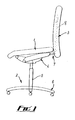
- Fig. 1 shows an office chair having a seat part 1, a base part 2, and a back part 3, all interconnected via a tilt mechanism 4.
- the base part comprises a vertical central support pillar 5 attached at its lower end to a five-arm wheeled floor-engaging structure 6. At its upper end the pillar 5 is attached to the tilt mechanism 4 beneath the seat part 1.
- the pillar 5 contains a gas cylinder height adjusting mechanism which is operated by a manual control (not shown) comprising a cam on a shaft which engages with a valve at the end of the gas cylinder on operation of the shaft by means of a control knob or lever.
- the seat part 1 comprises a padded seat structure on a frame which is attached to the tilt mechanism 4.
- the back part 3 comprises a padded back structure which is adjustably attached to an upstanding arm of a rigid L-shaped plate member 7 which is attached to the tilt mechanism 4.
- the mechanism 4 permits adjustment of inclination of the seat part 1.
- a suitable mechanism is disclosed in our copending application 9802447.4.
- the L-shaped plate member 7 is a rigid metal member which has a main upstanding limb 8 having straight, mutually parallel edges 9 and flat front and back mutually parallel faces 10, 11.
- the member 7 also has a shorter, forwardly directed lower limb 12 which has edges and opposite faces coextensive with the edges 9 and faces 10, 11 of the main limb 8, although the free end of this limb 12 is tapered to define a narrower flange with fixing holes.
- a slider 13 fits around the main limb 8 so as to be movable longitudinally of this.
- the slider 13 is in the form of a sleeve defined by two metal plates 14, 15 having flat main regions 16, 17 slightly wider than the main limb 8, and outwardly projecting edge regions 18, 19 stepped inwardly through a distance slightly greater than half the thickness of the limb 8.
- the two edge regions 18, 19 of the two plates are fixed together in face to fact contact whereby the main regions 16, 17 are spaced apart by slightly more than the thickness of the limb 8.
- the main region 16 of the front plate 14 has a longitudinally extending central part which is stepped outwardly to define a central channel 20.
- the main region 17 of the back plate 15 has a central longitudinally extending shaped cut-out 21 which defines first and second toothed racks 22, 23 with arcuate spaces 24, 25 between pointed teeth 26, 27.
- the racks 22, 23 are straight and extend, in mutually spaced apart disposition longitudinally of the main limb 8.
- the cut out 21 has an inclined shoulder 28 extending downwardly and forwardly away from the rack 22, leading from the lowermost rack space 24.
- an inclined shoulder 29 which extends downwardly and forwardly away from the rack 22 leading from the uppermost rack space 24.
- the slider 13 can be positioned on the main limb 8 such that these slots 30, 31 are located within the cut out 21 of the back plate 15 and within the channel 20 of the front plate 14.
- a first one of the slots 30 is configured for use with the first rack 22.
- This slot 30 has one end 32 within the region of the bottoms of the curved rack spaces 24, and the slot 30 extends upwardly from this end away from the rack to a slightly downwardly extending intermediate resting position 33 and from there to an upwardly extending part terminating in an enlarged top end 34.
- a second one of the slots 31 is configured for use with the second rack 23.
- This slot 31 has one end 35 level within the region of the bottoms of the curved rack spaces 25, and the slot 31 extends from there inwardly away from the rack and then upwardly terminating in an enlarged end portion 36.
- a pawl member 37 engageable between the teeth 26, 27 of the respective rack 22, 23.
- the pawl member 37 is in the form of a stud having a central cylindrical body part 38 which slides easily along the slot, and respective enlarged cylindrical heads 39 (of different diameters) on opposite ends which fit on opposite sides of the main limb 8 and retain the stud 37 in the slot 30, 31.
- the channel 20 of the front plate 14 of the slider 13 provides space for the adjacent (smaller diameter) head 39 of the pawl member 37.
- the slider 13 is fixed to the chair back part 3 by fixing studs or bolts engaging holes in the end regions 18, 19 and also holes in a mounting plate (not shown) within the back part 3.
- the slider 13 can slide up and down on the main limb 8 to enable the height of the back part 3 to be adjusted.
- the back part 3 can be held securely in an adjusted position by engagement of the pawl member 37 with one of the racks 22, 23 in a manner yet to be described.
- a guide arrangement is provided as follows:
- the main limb 8 is provided with two spaced apart mutually parallel V-shaped grooves 40, 41 on each of its front and back faces 10, 11.
- the grooves 40, 41 run parallel to the edges 9 and the grooves 40, 41 on one side are in direct superimposed relationship with regard to the grooves 40, 41 on the other side of the limb 8.
- the grooves 40, 41, on one side are identical, with regard to length, width, depth and profile, with the grooves 40, 41 on the other side.
- the grooves 40, 41 are formed by a stamping or pressing operation whereby the dimensions and particularly the depths of the grooves, and hence the separation of the bottom of superimposed grooves, can be precisely controlled.
- the grooves 40, 41 are near to the edges 9 of the main limb 8, within the area of the parts of the main regions 16, 17 of the slider plates 14, 15, outside the central cut out 21 and outside the central channel 20.
- projections 42, 43 may comprise strong inextensible cords or filaments (e.g. nylon filaments) fixed at their ends (e.g. by knotting through holes in the plates), or as shown in Figs. 9 and 10 they may comprise purpose made plastics extrusions 44 fixed to the plates 14, 15.
- strong inextensible cords or filaments e.g. nylon filaments
- they may comprise purpose made plastics extrusions 44 fixed to the plates 14, 15.
- the height adjustment mechanism so far described can be set up to be of the conventional kind requiring an external manual release lever, or of the known kind requiring no external release lever.
- the pawl member 37 is disposed within the slot 30 provided for use with the first rack 22.
- the pawl member 37 drops to the bottom end 32 of the slot 30 under the influence of gravity and engages one of the rack spaces 24. Any attempt at moving the back part 3 and the slider 13 downwardly jams the rack 22 against the pawl member 37 and securely resists this movement.
- Height adjustment is effected by lifting the back part 3 so that the pawl member 37 is deflected up the slot 30 to the intermediate resting position 33 by the action of the teeth 26 and the shoulder 28.
- the back part 3 can then be pushed down until the pawl member 37 is deflected by the top shoulder 29 back to the bottom of the slot 30 to engage the uppermost rack space 24.
- the back part 3 can then be lifted to cause the pawl member 37 to engage lower rack spaces 24 one by one until the desired height is reached.
- the mechanism can be set up to use the second rack 23 by removing the pawl member 37 from the enlarged top end 34 of the slot 30, and inserting it into the other slot 31 through the enlarged top end 36 of this.
- the pawl member 37 then engages the second rack 23 by gravity (or if desired by spring pressure) and, in conventional manner the height of the seat part is adjusted by moving the pawl member 37 out of engagement with the rack with a manual lever, the pawl member 37 being released to reengage the rack 23 when the desired height has been attained.
- the manual lever may cause a locking bar (not shown) to slide up and down engaging the end of the pawl member 37 through a shaped slot 45 in the front plate 1 as shown in Fig. 4, another slot 46 being provided for a guide link between the plate 14 and the locking bar.
- a locking bar (not shown) to slide up and down engaging the end of the pawl member 37 through a shaped slot 45 in the front plate 1 as shown in Fig. 4, another slot 46 being provided for a guide link between the plate 14 and the locking bar.
Landscapes
- Chairs Characterized By Structure (AREA)
Applications Claiming Priority (2)
| Application Number | Priority Date | Filing Date | Title |
|---|---|---|---|
| GBGB9811209.7A GB9811209D0 (en) | 1998-05-22 | 1998-05-22 | Height adjustment for back part of chair |
| GB9811209 | 1998-05-22 |
Publications (1)
| Publication Number | Publication Date |
|---|---|
| EP0958764A1 true EP0958764A1 (fr) | 1999-11-24 |
Family
ID=10832663
Family Applications (1)
| Application Number | Title | Priority Date | Filing Date |
|---|---|---|---|
| EP99304007A Withdrawn EP0958764A1 (fr) | 1998-05-22 | 1999-05-24 | Méchanisme de glissement |
Country Status (4)
| Country | Link |
|---|---|
| US (1) | US6273384B1 (fr) |
| EP (1) | EP0958764A1 (fr) |
| CA (1) | CA2272471A1 (fr) |
| GB (2) | GB9811209D0 (fr) |
Families Citing this family (6)
| Publication number | Priority date | Publication date | Assignee | Title |
|---|---|---|---|---|
| US7341233B2 (en) * | 2003-09-19 | 2008-03-11 | L & P Property Management Company | Horizontal adjustment mechanism for use on a chair seat |
| WO2006138382A2 (fr) | 2005-06-14 | 2006-12-28 | Micrablate, Llc | Outil de resection de tissus a ondes millimetriques |
| USD736551S1 (en) * | 2013-09-23 | 2015-08-18 | Yu-Shan Lai | Elevating part of a chair back |
| US9839276B2 (en) * | 2015-09-03 | 2017-12-12 | Woo Sung Yun | Nail clipper with adjustable cutting jaw |
| CN205321837U (zh) * | 2016-01-25 | 2016-06-22 | 浙江誉越家具有限公司 | 一种高度可调的扶手 |
| US11191361B2 (en) * | 2019-02-22 | 2021-12-07 | Includehealth, Inc. | Seat adjustment mechanism |
Citations (4)
| Publication number | Priority date | Publication date | Assignee | Title |
|---|---|---|---|---|
| US4749230A (en) | 1987-04-23 | 1988-06-07 | Tornero Lino E | Height adjusting device for chair backrest |
| EP0587536A1 (fr) * | 1992-09-09 | 1994-03-16 | CO.FE.MO. S.p.A. | Mécanisme pour le réglage en hauteur du dossier des chaises |
| US5547253A (en) * | 1994-08-11 | 1996-08-20 | Schwartz, Deceased; Edward M. | Sit/stand adjustable, tower chair |
| FR2732870A1 (fr) * | 1995-04-11 | 1996-10-18 | Thomas Frederique Chantal | Dispositif d'interchangeabilite d'un decor de dossier de chaise ou de tout autre mobilier |
Family Cites Families (21)
| Publication number | Priority date | Publication date | Assignee | Title |
|---|---|---|---|---|
| GB1371641A (en) | 1971-11-23 | 1974-10-23 | Parnall & Sons Ltd | Chairs |
| US4012158A (en) * | 1975-09-15 | 1977-03-15 | Harper Henry J | Adjustable seat-back mechanism |
| US4451084A (en) * | 1981-12-14 | 1984-05-29 | Simmons Universal Corporation | Backrest height adjustment for office chair |
| DE3527783A1 (de) * | 1985-08-02 | 1987-02-12 | Froescher August Gmbh Co Kg | Verstelleinrichtung fuer die stufenweise arretierbare hoehenverstellung von rueckenlehnen an arbeitsstuehlen |
| US4639039A (en) | 1985-09-10 | 1987-01-27 | Milsco Manufacturing Company | Height adjustment mechanism for chair backrest |
| US5026117A (en) | 1987-11-10 | 1991-06-25 | Steelcase Inc. | Controller for seating and the like |
| US4930840A (en) * | 1989-07-03 | 1990-06-05 | Tornero Lino E | Hinged height adjusting device |
| US5037158A (en) * | 1990-01-16 | 1991-08-06 | Westinghouse Electric Corporation | Height adjustment mechanism for chair back |
| US5375912A (en) | 1990-08-10 | 1994-12-27 | Stulik; Edward L. | Reclining chair |
| JP2919131B2 (ja) | 1991-10-22 | 1999-07-12 | 株式会社イトーキクレビオ | 椅子の傾動制御装置 |
| DE4312113C1 (de) | 1993-04-14 | 1994-10-27 | Mauser Waldeck Ag | Sitzmöbel |
| US5582460A (en) * | 1993-06-11 | 1996-12-10 | Hon Industries Inc. | Pivotable and height-adjustable chair back rest assembly and blow-molded back rest therefor |
| IT239565Y1 (it) * | 1995-03-21 | 2001-03-05 | Miotto Internat Company | Dispositivo di regolazione dell'altezza di uno schienale di una sedia |
| DE29508082U1 (de) | 1995-05-17 | 1995-09-14 | Martin Bock Kunststoffverarbeitung, 92353 Postbauer-Heng | Stuhl, insbesondere Bürostuhl, mit einer höhenverstellbaren Rückenlehnenkonstruktion |
| US5586809A (en) * | 1995-08-04 | 1996-12-24 | Herman Miller, Inc. | Height adjustment mechanism for a chair backrest |
| US5597204A (en) * | 1995-08-04 | 1997-01-28 | Herman Miller, Inc. | Height adjustment device |
| US5649741A (en) | 1996-02-16 | 1997-07-22 | Northfield Metal Products Ltd. | Adjusting mechanism |
| US5695249A (en) * | 1996-06-24 | 1997-12-09 | Lotfi; Mehdian | Height adjustment mechanism for chair components |
| US5918935A (en) | 1997-06-03 | 1999-07-06 | Stulik; Edward L. | Reclining chair |
| US5853222A (en) * | 1997-06-06 | 1998-12-29 | Haworth, Inc. | Height-adjustable chair back |
| US5951107A (en) * | 1998-10-28 | 1999-09-14 | Tornero; Lino E. | Height adjusting device with audible feedback |
-
1998
- 1998-05-22 GB GBGB9811209.7A patent/GB9811209D0/en not_active Ceased
-
1999
- 1999-05-21 US US09/316,204 patent/US6273384B1/en not_active Expired - Fee Related
- 1999-05-21 CA CA002272471A patent/CA2272471A1/fr not_active Abandoned
- 1999-05-24 EP EP99304007A patent/EP0958764A1/fr not_active Withdrawn
- 1999-05-24 GB GB9911869A patent/GB2338646B/en not_active Expired - Fee Related
Patent Citations (4)
| Publication number | Priority date | Publication date | Assignee | Title |
|---|---|---|---|---|
| US4749230A (en) | 1987-04-23 | 1988-06-07 | Tornero Lino E | Height adjusting device for chair backrest |
| EP0587536A1 (fr) * | 1992-09-09 | 1994-03-16 | CO.FE.MO. S.p.A. | Mécanisme pour le réglage en hauteur du dossier des chaises |
| US5547253A (en) * | 1994-08-11 | 1996-08-20 | Schwartz, Deceased; Edward M. | Sit/stand adjustable, tower chair |
| FR2732870A1 (fr) * | 1995-04-11 | 1996-10-18 | Thomas Frederique Chantal | Dispositif d'interchangeabilite d'un decor de dossier de chaise ou de tout autre mobilier |
Also Published As
| Publication number | Publication date |
|---|---|
| GB2338646B (en) | 2002-06-26 |
| CA2272471A1 (fr) | 1999-11-22 |
| GB9811209D0 (en) | 1998-07-22 |
| US6273384B1 (en) | 2001-08-14 |
| GB9911869D0 (en) | 1999-07-21 |
| GB2338646A (en) | 1999-12-29 |
Similar Documents
| Publication | Publication Date | Title |
|---|---|---|
| US6974189B2 (en) | Vertically adjustable chair armrest | |
| CA2197028C (fr) | Mecanisme de reglage | |
| US5620233A (en) | Adjusting mechanism for selectively positioning chair components | |
| US5393125A (en) | Height adjustable chair arm assembly | |
| US6299253B1 (en) | Telescopic positioning mechanism for chair backrest | |
| US5951107A (en) | Height adjusting device with audible feedback | |
| EP1192875B1 (fr) | Ensemble d'accoudoir pour chaise | |
| US6598937B2 (en) | Adjustable backrest | |
| EP0818597B1 (fr) | Système de verrouillage avec fermeture à barre pour tiroirs | |
| CA2171651C (fr) | Mecanisme de reglage de la hauteur du dossier d'une chaise | |
| US20050146192A1 (en) | Horizontally adjustable chair armrest | |
| US9861205B2 (en) | Armrest mechanism for a chair | |
| JP4297941B2 (ja) | 椅子のための高さ調節機構 | |
| US4924725A (en) | Mechanism for adjusting height of handle bar of pushcart | |
| EP0836819A3 (fr) | Ensemble d'appui-bras réglable en hauteur | |
| US6273384B1 (en) | Chair back adjustment mechanism | |
| EP1568297A1 (fr) | Chaise à accoudoir fonctionnel | |
| US7341233B2 (en) | Horizontal adjustment mechanism for use on a chair seat | |
| CN1229342A (zh) | 调节特别是办公椅座背部分靠背高度的装置 | |
| US5791734A (en) | Chair with a backrest which is continuously adjustable height | |
| US6793286B2 (en) | Chair adjustment mechanism | |
| US6517158B1 (en) | Height-adjustable armrest assembly | |
| EP1753319B1 (fr) | Element-support de dossiers/ accoudoir pour chaises, en particulier chaises de bureau | |
| US6840581B2 (en) | Height adjustment arrangement for chair headrest | |
| KR102366832B1 (ko) | 의자의 등판 높이 조절기구 |
Legal Events
| Date | Code | Title | Description |
|---|---|---|---|
| PUAI | Public reference made under article 153(3) epc to a published international application that has entered the european phase |
Free format text: ORIGINAL CODE: 0009012 |
|
| AK | Designated contracting states |
Kind code of ref document: A1 Designated state(s): DE DK ES FR GR IE IT NL |
|
| AX | Request for extension of the european patent |
Free format text: AL;LT;LV;MK;RO;SI |
|
| 17P | Request for examination filed |
Effective date: 20000522 |
|
| AKX | Designation fees paid |
Free format text: DE DK ES FR GR IE IT NL |
|
| 17Q | First examination report despatched |
Effective date: 20020613 |
|
| STAA | Information on the status of an ep patent application or granted ep patent |
Free format text: STATUS: THE APPLICATION IS DEEMED TO BE WITHDRAWN |
|
| 18D | Application deemed to be withdrawn |
Effective date: 20021203 |