EP0958848A2 - Dispositif de retenue pour barres de sauts d'obstacles - Google Patents
Dispositif de retenue pour barres de sauts d'obstacles Download PDFInfo
- Publication number
- EP0958848A2 EP0958848A2 EP99108491A EP99108491A EP0958848A2 EP 0958848 A2 EP0958848 A2 EP 0958848A2 EP 99108491 A EP99108491 A EP 99108491A EP 99108491 A EP99108491 A EP 99108491A EP 0958848 A2 EP0958848 A2 EP 0958848A2
- Authority
- EP
- European Patent Office
- Prior art keywords
- rail
- slots
- head
- slot
- adapter
- Prior art date
- Legal status (The legal status is an assumption and is not a legal conclusion. Google has not performed a legal analysis and makes no representation as to the accuracy of the status listed.)
- Granted
Links
- 230000009191 jumping Effects 0.000 title claims description 4
- 229920002430 Fibre-reinforced plastic Polymers 0.000 claims description 3
- 239000011151 fibre-reinforced plastic Substances 0.000 claims description 3
- 230000037431 insertion Effects 0.000 claims 1
- 238000003780 insertion Methods 0.000 claims 1
- 239000000463 material Substances 0.000 description 8
- 230000006378 damage Effects 0.000 description 4
- 125000006850 spacer group Chemical group 0.000 description 4
- 208000027418 Wounds and injury Diseases 0.000 description 2
- 210000000003 hoof Anatomy 0.000 description 2
- 208000014674 injury Diseases 0.000 description 2
- 230000007704 transition Effects 0.000 description 2
- 229910000831 Steel Inorganic materials 0.000 description 1
- 229910052782 aluminium Inorganic materials 0.000 description 1
- XAGFODPZIPBFFR-UHFFFAOYSA-N aluminium Chemical compound [Al] XAGFODPZIPBFFR-UHFFFAOYSA-N 0.000 description 1
- 230000037396 body weight Effects 0.000 description 1
- 238000010276 construction Methods 0.000 description 1
- 229910052751 metal Inorganic materials 0.000 description 1
- 239000002184 metal Substances 0.000 description 1
- 239000004033 plastic Substances 0.000 description 1
- 229920003023 plastic Polymers 0.000 description 1
- 239000010959 steel Substances 0.000 description 1
- 239000000725 suspension Substances 0.000 description 1
- 230000003313 weakening effect Effects 0.000 description 1
- 239000002023 wood Substances 0.000 description 1
Images




Classifications
-
- A—HUMAN NECESSITIES
- A63—SPORTS; GAMES; AMUSEMENTS
- A63K—RACING; RIDING SPORTS; EQUIPMENT OR ACCESSORIES THEREFOR
- A63K3/00—Equipment or accessories for racing or riding sports
- A63K3/04—Hurdles or the like
- A63K3/046—Equestrian hurdles
-
- F—MECHANICAL ENGINEERING; LIGHTING; HEATING; WEAPONS; BLASTING
- F16—ENGINEERING ELEMENTS AND UNITS; GENERAL MEASURES FOR PRODUCING AND MAINTAINING EFFECTIVE FUNCTIONING OF MACHINES OR INSTALLATIONS; THERMAL INSULATION IN GENERAL
- F16B—DEVICES FOR FASTENING OR SECURING CONSTRUCTIONAL ELEMENTS OR MACHINE PARTS TOGETHER, e.g. NAILS, BOLTS, CIRCLIPS, CLAMPS, CLIPS OR WEDGES; JOINTS OR JOINTING
- F16B7/00—Connections of rods or tubes, e.g. of non-circular section, mutually, including resilient connections
- F16B7/22—Connections of rods or tubes, e.g. of non-circular section, mutually, including resilient connections using hooks or like elements
-
- F—MECHANICAL ENGINEERING; LIGHTING; HEATING; WEAPONS; BLASTING
- F16—ENGINEERING ELEMENTS AND UNITS; GENERAL MEASURES FOR PRODUCING AND MAINTAINING EFFECTIVE FUNCTIONING OF MACHINES OR INSTALLATIONS; THERMAL INSULATION IN GENERAL
- F16B—DEVICES FOR FASTENING OR SECURING CONSTRUCTIONAL ELEMENTS OR MACHINE PARTS TOGETHER, e.g. NAILS, BOLTS, CIRCLIPS, CLAMPS, CLIPS OR WEDGES; JOINTS OR JOINTING
- F16B2200/00—Constructional details of connections not covered for in other groups of this subclass
- F16B2200/20—Connections with hook-like parts gripping behind a blind side of an element to be connected
-
- Y—GENERAL TAGGING OF NEW TECHNOLOGICAL DEVELOPMENTS; GENERAL TAGGING OF CROSS-SECTIONAL TECHNOLOGIES SPANNING OVER SEVERAL SECTIONS OF THE IPC; TECHNICAL SUBJECTS COVERED BY FORMER USPC CROSS-REFERENCE ART COLLECTIONS [XRACs] AND DIGESTS
- Y10—TECHNICAL SUBJECTS COVERED BY FORMER USPC
- Y10S—TECHNICAL SUBJECTS COVERED BY FORMER USPC CROSS-REFERENCE ART COLLECTIONS [XRACs] AND DIGESTS
- Y10S403/00—Joints and connections
- Y10S403/03—Load-responsive release
Definitions
- the present invention relates to a holder for rods of jump obstacles in the Equestrian sport, with a cup-shaped pole mount, which on a generally vertically arranged rail of a stand is suspended, the receptacle and the Rails over head bolts that extend from one of the two parts into slots on the other of the extend two parts, are connected to each other and wherein the slots are narrow Have slot parts with a width that is approximately the width of the shaft of the head bolts corresponds to and is less than the diameter of the head of the head bolts, and one Have widening through which the heads of the head bolts can be inserted in order to this way the head bolts can be inserted into the slots and inserted into the to be able to lock the narrow slot part.
- Such pole holders have long been for the obstacles in horse jumping known.
- the bars generally made of wood or aluminum with a Diameters on the order of 15 cm are correspondingly concave trained, cup-shaped pad inserted so that they are horizontal in the case Pushing the hooves of a horse jumping over the obstacle onto the pole from the cup-shaped receptacle can be moved forwards or backwards and fall down.
- This Occasionally happens when the horse "skips" an obstacle when it is not jumps off optimally, for example a little too flat, jumps off too early or too late or also deflects with the hind feet during the jump.
- a jump may fail completely, be that that Horse tries at the last moment to stop in front of the obstacle, or too early or too jumps off late, although all of this can also be due to mistakes made by the rider.
- the horse may step deep between the obstacle poles with its hooves and can possibly also put a heavy load on the obstacle bars with his body weight and will generally slip off the rack.
- the object of the present invention is therefore in relation to this prior art to create a bracket with the features mentioned, with which the demands made are easier to fulfill, i.e. which at a given and yields relatively low vertical load, so that the rod or the rod holder when this load is exceeded is released down, with a destruction or Damage to the rod holder should be avoided if possible.
- slots on their from widening opposite end are open, in the form of an opposite to the narrow Slot part tapered slot section, the width of which is dimensioned so that in the narrow slot part received bolts or bolt shafts only by overcoming the predetermined force acting in the longitudinal direction of the slot in this tapered slot section are movable in and to the open end of the slot.
- the present invention provides that the head bolts receiving slots are open in the direction of the vertical load occurring, however only in the form of a tapered slot section that is narrower than the shaft of the bolt, so that at normal loads, i.e. by the weight of the obstacle bar and even if a normally built person sits on the obstacle pole, not can enter and pass through this narrow slot section.
- the rail having the corresponding slots or a corresponding rail section can according to an embodiment of the invention with the rod support, namely be connected in one piece on the side facing away from the cup-shaped rod receptacle. Accordingly, the head bolts would have to be arranged on a stand and the slot would be open at the top, so that the support with the rail section attached to it at a corresponding load would be moved down, the bolt relative to the rail would be moved up out of the slots.
- an embodiment of the invention is preferred in which the inventive flexible connection is realized by an intermediate adapter part by namely a conventional rail on a stand with a large number of vertical aligned slots are used, in which the adapter with its Back-mounted headed studs in the usual manner in any desired manner Height can be hooked.
- the adapter itself is then like a conventional one Bar support firmly locked in the slots in the stand.
- the adapter facing the rod support has a rail or one Rail section with the slot design according to the invention, so that in turn a conventional rod support in these slots of the adapter designed according to the invention can be hung.
- the head bolts are accordingly firmly connected to the rod support.
- adapter construction could reverse the assignment of slots and head bolts done by the adapter on its side facing the rod support one or two Head bolts, which in the corresponding, in the normal state of use open at the top Slots could engage a rail firmly connected to the support.
- a head pin adapter can also be used, i.e. a plate or a small one Block, the one or both on each side or two or in the required pitch has more head bolts, the head bolts on one side into a conventional one Stand rail could be hooked in while the head bolt (s) are on the other Page in the invention with one or more, in this case open to the top, Slotted rail would be hung on a bar support.
- An embodiment of the invention is particularly preferred and expedient in which a bracket each provided two bolts vertically one above the other and are particularly attached to the edition.
- the same one above the other in corresponding Slots arranged head bolts thus prevent rotation of the bracket or Support around the bolt axis or an axis parallel to the bolt axis, as in Using only a single bolt would be possible.
- this configuration it is makes sense if only one of the two slots in which the head bolts are accommodated has the tapered slot portion that widens at the predetermined compressive force, to let the bolt shaft pass through while the other of the two slots is completely open, i.e. consistently has the width of the narrow slot section that the Thickness of the bolt shaft corresponds.
- the corresponding rail section for example on an adapter, two vertically at a distance has slits arranged one above the other, each having a widening, the the two spacings have the same distance as the heads of the head bolts on the corresponding counterpart and the two slots either over a tapered Slot section that is narrower than the head bolt shafts are wide, or over one narrow slot section, which corresponds to this shaft width, are connected to one another, in the latter case a correspondingly tapered, open slot section on which the Slot connection facing end of one of the two slots should be arranged.
- the tapered one is the most important Rail with slot area made of a fiber-reinforced plastic material, preferably also the rod holder is made of the same material.
- a rod holder 10 which consists essentially of a concave Support shell 12 and a support plate 11.
- a concave support shell 12 To support the concave support shell 12, as can be seen above all in FIG. 2, are still on the side of the vertical support plate 11 triangular supports 13 are provided.
- head bolts 15 At the back of the support plate 11 are vertical one above the other and at a distance from each other two head bolts 15 are provided, which essentially from a bolt head 7 rounded on its outside, one opposite the bolt head 7 tapered bolt shaft 8 and an inner bolt core 9 exist.
- the entire rod holder 10 is in one piece and preferably from one fiber-reinforced plastic material made, the bolt core 9 made of metal, preferably consists of steel and integrated in the plastic material of the receptacle or is poured. A predetermined shear force for the bolt is created by the bolt core 9 15 defined.
- the head 7 of the headed bolt 15 is on its side facing the shaft flat and flat, the flat underside of the head 7 perpendicular to Bolt axis extends.
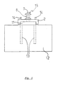
- Figure 3 shows the front view of an adapter rail, which is U-shaped or H-shaped in cross section is formed, one in the front view in the lower part of the adapter rail recognizes a continuous slot 3, which consists of two narrow slot parts 4th composed, vertically one above the other and with each other in the longitudinal direction of the rail are aligned, at their upper end each an approximately circular Have slot widening 5 and again with respect to the narrow slot part 4 tapered slot section 6 are interconnected.
- the top slot consists of the slot widening 5 arranged at the top, one adjoining it at the bottom narrow slot section 4 and the subsequent tapered slot section 6, the lower, open end immediately merges into the widening 5 of the arranged below Slot, at the bottom only another narrow slot section 4th connects, which is open without further tapering downwards, although here again one further taper 6 of the slot could be provided.
- Such a mounting rail which is not shown here, generally has a large number vertically with one another in the mentioned grid dimension arranged slots, which differ from the slot 3 or the slot parts 4, 5 only thereby distinguish that they are not connected by a tapered slot section 6 are, but that there is this tapered slot section 6 through a closed wall is replaced.
- the transition from the narrow slot part 4 to the again tapered slot section 6 can be designed differently.
- it can be part-circular or it can be provided here essentially flat, diagonally converging diaphragm walls become.
- the shaft cross-section of the bolt does not have to be circular, but can be used for Example adapted to the transition mentioned or a cross-sectional shape that is independent of this to have.
- the heads of the head bolts do not have to be circular when viewed from above, but can be any, the expansion and / or the adjacent slot part 4th have an adapted shape, for example with one in the narrow slot section 4 protruding nose be provided that a clear relative orientation when inserted between the head pin and slot or between the rod holder and rail.
- the grid dimension of the slots or slot widenings 5 on the front of the adapter rail in this exemplary embodiment again corresponds exactly to the grid dimension of the Head bolts on the back of the rod holder match, however, this grid dimension not necessarily with the pitch of the head bolts on the back of the adapter rail 1 must match. If these grid dimensions are made to match, this has the advantage that any conventional rod holders are used to hang them in the adapter rail instead of in a stand rail. This should be however only happen when the bolt shafts 8 of the headed bolts are corresponding have uniform dimensions, so that even when using conventional rod holders the desired flexibility of the tapered slot section 6 at the predetermined Limit force is given.
- Figure 5 which corresponds to a top view of Figure 4, shows the U-shaped again Cross section of the adapter rail 1, which consists of the U-profile 2, but on which two spacer rails 14 are formed or welded onto the rear side.
- the height of this spacer 14 is such that the heads 7 of the head bolts Bar receptacle 10 in the space between the spacer rails 14 can be included if the heads 7 of the head bolts 15 on the back of the Adapter rail 1 are suspended in a corresponding rail of a stand.
- Figure 4 it is clearly visible that the heads 7 of the head bolts 15 of the rod holder 10 do not have the rear edge of these spacer rails 14 protrude.
- FIG. 6a to c show a variant 1 'of an adapter rail, which in the present case has a box-shaped profile.
- FIG. 6a shows the top view of the adapter rail 1 from the front, analogous to the top view according to FIG. 3 on the adapter rail 1.
- one Rod holder 10 two additional slots parallel to slot section 6 or Elongated holes 16 are provided which allow the tapered slot section 6 to bend elastically should facilitate, which connects the upper and lower slot together.
- This Design leads to the fact that the material of the adapter rail during the expansion of the tapered slot section 6 by a correspondingly loaded head bolt shaft is less loaded than in the case of the embodiment shown in Figures 3 and 4 could happen.
- the adapter rail shown in FIGS. 6a-c has a box-shaped shape Cross-section the advantage that it compared to the rail shown in Figures 3 to 5 can be made shorter because the head bolts 15 on the back of the adapter rail 1 'are arranged on the rear wall of the box section and thus vertically at the same height can be arranged like that in the front wall of the box-shaped profile provided slots.
- the cutting lines, the position of the in Figures 6b and 6c show sectional planes shown are indicated by dashed lines B-B and C-C.
- FIGS. 7 and 8 each show an embodiment in which the rod holder, which is designated here by a total of 20 or 20 ', in the form of a rail piece with a spreadable slot is formed.
- a headed pin adapter 21 or 21 ' is provided to this rod holder also on conventional To be able to hang up stands.
- the conventional stands have slots with extensions into which the head pin adapter with two stacked head bolts 15, which are on one side of a Plate 17 are located, can be hung.
- the distance between two widenings 5 of a corresponding rail 18 corresponds to a rod holder 20 (see FIGS. 7b, 7c).
- the distance between the head bolts 15 on both sides of the head bolt adapter 21 could also be be different, the distance on one side with the corresponding The spacing of the slot widenings on a rail matches, while the head bolt spacing on the other hand with the spacing of the slot widenings 5 on the Rail section 18 should match.
- the head bolts do not have an exact circular cross-section, but one Expansion in the slot direction, which has a specific orientation of the head pin adapter 21 displays.
- the rod holder 20 is either designed as a U-shaped flat material, can but also have a box profile in cross section analogous to FIG. 6c. However, then Corresponding parallel elongated holes 16 may also be required to expand of the tapered slot section 6 with the intended force.
- FIG. 7c shows a section through the rod holder 20 along the line C-C in FIG. 6b.
- the design of the slots is practically identical to the design of the Slits in the previously described embodiments according to FIGS. 3 and 4.
- the embodiment according to FIG. 8 differs from the embodiment according to FIG 7 essentially only in that the rod receptacle 20 'is not bent or U-shaped is made as a box profile, but from a flat flat material 18 ', then however, the bowl-shaped rod support 12 with the struts 13 compared to the Slits are staggered lengthways to avoid any interference between the bar rest 12 and to avoid the slots or the head bolts 15 inserted into the slots, too if it were possible in principle to design the entire rod holder so that the Slots are arranged above and below the bowl-shaped support 12.
- the adapters 21 and 21 'could be used in the embodiments of the figures 7 and 8 can also be exchanged for each other or you only needed a single type a head pin adapter, for example the head pin adapter 21 ', for both variants of To provide rod holders 20 or 20 '.
Landscapes
- Engineering & Computer Science (AREA)
- General Engineering & Computer Science (AREA)
- Mechanical Engineering (AREA)
- Mutual Connection Of Rods And Tubes (AREA)
- Clamps And Clips (AREA)
- Forklifts And Lifting Vehicles (AREA)
- Earth Drilling (AREA)
- Contacts (AREA)
- Springs (AREA)
- Leg Units, Guards, And Driving Tracks Of Cranes (AREA)
- Passenger Equipment (AREA)
- Connection Of Plates (AREA)
- Vehicle Step Arrangements And Article Storage (AREA)
- Fittings On The Vehicle Exterior For Carrying Loads, And Devices For Holding Or Mounting Articles (AREA)
Priority Applications (2)
| Application Number | Priority Date | Filing Date | Title |
|---|---|---|---|
| EP04103294A EP1475135B1 (fr) | 1998-05-13 | 1999-04-30 | Dispositif de retenue pour barres de sauts d'obstacles |
| DK04103294T DK1475135T3 (da) | 1998-05-13 | 1999-04-30 | Holder til bomme til springforhindringer |
Applications Claiming Priority (2)
| Application Number | Priority Date | Filing Date | Title |
|---|---|---|---|
| DE19821398 | 1998-05-13 | ||
| DE19821398A DE19821398A1 (de) | 1998-05-13 | 1998-05-13 | Halterung für Stangen von Sprunghindernissen |
Related Child Applications (2)
| Application Number | Title | Priority Date | Filing Date |
|---|---|---|---|
| EP04103294A Division EP1475135B1 (fr) | 1998-05-13 | 1999-04-30 | Dispositif de retenue pour barres de sauts d'obstacles |
| EP04103294.7 Division-Into | 2004-07-12 |
Publications (3)
| Publication Number | Publication Date |
|---|---|
| EP0958848A2 true EP0958848A2 (fr) | 1999-11-24 |
| EP0958848A3 EP0958848A3 (fr) | 2000-05-24 |
| EP0958848B1 EP0958848B1 (fr) | 2005-11-23 |
Family
ID=7867615
Family Applications (2)
| Application Number | Title | Priority Date | Filing Date |
|---|---|---|---|
| EP04103294A Expired - Lifetime EP1475135B1 (fr) | 1998-05-13 | 1999-04-30 | Dispositif de retenue pour barres de sauts d'obstacles |
| EP99108491A Expired - Lifetime EP0958848B1 (fr) | 1998-05-13 | 1999-04-30 | Dispositif de retenue pour barres de sauts d'obstacles |
Family Applications Before (1)
| Application Number | Title | Priority Date | Filing Date |
|---|---|---|---|
| EP04103294A Expired - Lifetime EP1475135B1 (fr) | 1998-05-13 | 1999-04-30 | Dispositif de retenue pour barres de sauts d'obstacles |
Country Status (6)
| Country | Link |
|---|---|
| US (2) | US6234708B1 (fr) |
| EP (2) | EP1475135B1 (fr) |
| AT (2) | ATE310574T1 (fr) |
| DE (4) | DE19821398A1 (fr) |
| DK (2) | DK1475135T3 (fr) |
| ES (2) | ES2276225T3 (fr) |
Families Citing this family (23)
| Publication number | Priority date | Publication date | Assignee | Title |
|---|---|---|---|---|
| DE19953688C1 (de) * | 1999-11-09 | 2001-02-15 | Herbert Schaefer | Vorrichtung zum Auflagern einer Stange oder eines anderen Hindernisteiles im Reitsport |
| GB0126314D0 (en) * | 2001-11-02 | 2002-01-02 | Barriers Internat Ltd | Improvements in and relating to barrier safety systems |
| NL1021107C2 (nl) * | 2002-07-18 | 2004-01-20 | Driessen Aircraft Holding B V | Modulaire kombuis voor in een vliegtuig of trein alsmede wand en module voor een dergelijke kombuis en daarmee uitgerust vliegtuig of trein. |
| DE10238528A1 (de) * | 2002-08-22 | 2004-03-04 | Robert Bosch Gmbh | Befestigungsanordnung |
| US6976452B1 (en) * | 2003-10-14 | 2005-12-20 | Godsil Mark R | Wire or rod jump cups |
| US20080083914A1 (en) * | 2004-07-19 | 2008-04-10 | Ochoa Carlos M | Posts and release mechanism for highway safety structures |
| US7530548B2 (en) * | 2004-07-19 | 2009-05-12 | Ochoa Carlos M | Releasable highway safety structures |
| DE102004060163B3 (de) * | 2004-12-14 | 2006-05-24 | Formen Und Werkzeugbau Josef Frech Kg | Zweiteilige Halterung für Stangen von Sprunghindernissen |
| US20070228238A1 (en) * | 2006-03-29 | 2007-10-04 | Engel John B | Self adjusting mounting holes |
| DE102006025574B4 (de) * | 2006-06-01 | 2012-02-16 | Herbert Schäfer | Sicherheitsauflage für eine Hindernisstange oder ein anderes Hindernisteil beim Reitsport |
| US20080067906A1 (en) * | 2006-08-23 | 2008-03-20 | Juten Robert | Modular components for building structures |
| US7798105B1 (en) | 2008-08-20 | 2010-09-21 | Picard Karen B | Method of instructing a horse to jump |
| EP2411546B1 (fr) * | 2009-03-26 | 2013-07-03 | Vishnukumar Mahadeo Kulkarni | Procédé de production d'un jus de fruit clarifié, d'un jus de fruit pouvant être conditionné, d'éthanol et de sucre à partir de la canne à sucre et système associé |
| US8192255B2 (en) * | 2010-02-11 | 2012-06-05 | Eric Gallup | Tool holder with tapered slot for a grinding machine |
| US20130103086A1 (en) * | 2011-10-19 | 2013-04-25 | Warsaw Orthopedic, Inc. | Spinous process mounted spinal implant |
| US20130334154A1 (en) * | 2012-06-18 | 2013-12-19 | Advanced Applications, Llc | Modular pegs for drying rack |
| CN103780197A (zh) * | 2012-10-23 | 2014-05-07 | 富昱能源科技(昆山)有限公司 | 太阳能模组支架组合 |
| JP6245043B2 (ja) * | 2014-04-02 | 2017-12-13 | 日立金属株式会社 | ノイズ抑制ケーブル |
| US11028869B2 (en) * | 2015-05-13 | 2021-06-08 | MAQUET CARDIOPULMONARY GmbH | Mount interface for a medical device |
| US9656184B1 (en) | 2016-03-23 | 2017-05-23 | Cristobal Castro | Sliding jump cup system, method and apparatus |
| CN107732812B (zh) * | 2017-11-08 | 2024-09-10 | 浙江连翔五金科技股份有限公司 | 通讯及电力支架 |
| CN110917639B (zh) * | 2019-12-03 | 2021-01-08 | 齐鲁理工学院 | 一种足球训练用可伸缩跨栏器械 |
| DE102021004143A1 (de) | 2021-08-12 | 2023-02-16 | Johann Friedrich Schweiger | Auslösbare Halterung für Geländehindernisse im Reitsport |
Family Cites Families (17)
| Publication number | Priority date | Publication date | Assignee | Title |
|---|---|---|---|---|
| BE786440A (fr) * | 1971-07-20 | 1973-01-19 | Interlake Inc | Verrou de charge |
| US3749344A (en) * | 1971-10-12 | 1973-07-31 | J Racina | Jump cup |
| DE7805866U1 (de) * | 1978-02-27 | 1978-07-27 | Alveru Sa, Freiburg (Schweiz) | Halterung fuer eine barriere als sprunghindernis |
| DE8007230U1 (de) * | 1980-03-15 | 1980-06-19 | Aluteam Sport- Und Freizeit Gmbh, 5440 Mayen | Springstaender fuer den reitsport |
| US4342687A (en) | 1981-09-08 | 1982-08-03 | Texaco Inc. | N-Substituted perhydrodioxazepines useful as polyurethane catalysts |
| US4655158A (en) * | 1985-02-19 | 1987-04-07 | Larry Holder | Boat anchor including releasable coupling means |
| US4989821A (en) * | 1989-06-05 | 1991-02-05 | Wong William P W | Support devices for producing variable height barriers |
| FI900637A7 (fi) | 1990-02-08 | 1991-08-09 | Erkki Eloranta | Hinderridningsstolpe. |
| GB9122088D0 (en) * | 1991-10-17 | 1991-11-27 | Savage Ltd | Free-standing shelving system |
| DE4227108C1 (de) * | 1992-08-17 | 1993-10-28 | Horst Richter | Hindernis für den Reitspringsport |
| DE4305550C2 (de) | 1993-02-24 | 1996-09-26 | Curt Bender | Halter zum Halten von Einhängeteilen bei Hindernissen für den Pferdesport |
| US5653349A (en) * | 1995-07-31 | 1997-08-05 | Akro-Mils | Offset stud fastener |
| US5690583A (en) * | 1996-09-06 | 1997-11-25 | Keusch; Joseph J. | Jump cup adapted to be manipulated by one hand |
| US5867877A (en) | 1997-08-15 | 1999-02-09 | Turtle Snaps, Inc. | Self-releasing coupler |
| US6063005A (en) | 1997-08-19 | 2000-05-16 | United Canvas & Sling, Inc. | Track and field hurdle and board supporting apparatus |
| US5967093A (en) | 1997-10-07 | 1999-10-19 | Topline Equine, Inc. | Equestrian jump and bracket for creating an angular obstacle |
| US5913283A (en) | 1997-10-20 | 1999-06-22 | Coury; Joseph S. | Equestrian barrier |
-
1998
- 1998-05-13 DE DE19821398A patent/DE19821398A1/de not_active Ceased
-
1999
- 1999-03-01 DE DE29908579U patent/DE29908579U1/de not_active Expired - Lifetime
- 1999-04-30 ES ES04103294T patent/ES2276225T3/es not_active Expired - Lifetime
- 1999-04-30 AT AT99108491T patent/ATE310574T1/de active
- 1999-04-30 AT AT04103294T patent/ATE345858T1/de active
- 1999-04-30 DK DK04103294T patent/DK1475135T3/da active
- 1999-04-30 DE DE59912812T patent/DE59912812D1/de not_active Expired - Lifetime
- 1999-04-30 EP EP04103294A patent/EP1475135B1/fr not_active Expired - Lifetime
- 1999-04-30 DE DE59914013T patent/DE59914013D1/de not_active Expired - Lifetime
- 1999-04-30 EP EP99108491A patent/EP0958848B1/fr not_active Expired - Lifetime
- 1999-04-30 ES ES99108491T patent/ES2251804T3/es not_active Expired - Lifetime
- 1999-04-30 DK DK99108491T patent/DK0958848T3/da active
- 1999-05-10 US US09/309,118 patent/US6234708B1/en not_active Expired - Lifetime
-
2001
- 2001-04-27 US US09/845,002 patent/US6416247B2/en not_active Expired - Lifetime
Non-Patent Citations (1)
| Title |
|---|
| None |
Also Published As
| Publication number | Publication date |
|---|---|
| EP1475135B1 (fr) | 2006-11-22 |
| EP0958848B1 (fr) | 2005-11-23 |
| ES2276225T3 (es) | 2007-06-16 |
| DE29908579U1 (de) | 1999-09-23 |
| ATE310574T1 (de) | 2005-12-15 |
| US6234708B1 (en) | 2001-05-22 |
| EP1475135A1 (fr) | 2004-11-10 |
| DE59912812D1 (de) | 2005-12-29 |
| ES2251804T3 (es) | 2006-05-01 |
| EP0958848A3 (fr) | 2000-05-24 |
| US20010016145A1 (en) | 2001-08-23 |
| DE59914013D1 (de) | 2007-01-04 |
| US6416247B2 (en) | 2002-07-09 |
| DK0958848T3 (da) | 2006-02-13 |
| ATE345858T1 (de) | 2006-12-15 |
| DK1475135T3 (da) | 2007-02-19 |
| DE19821398A1 (de) | 1999-11-18 |
Similar Documents
| Publication | Publication Date | Title |
|---|---|---|
| EP1475135B1 (fr) | Dispositif de retenue pour barres de sauts d'obstacles | |
| DE3128840A1 (de) | "rahmen zum transport und zur lagerung von rohren" | |
| DE1955955B2 (de) | Winkelverbindung zwischen einer Tragsäule und einer von dieser forttragenden Schiene | |
| EP2986498B1 (fr) | Plaque d'arrimage et moyen d'arrimage permettant l'arrimage de conteneurs sur un véhicule, en particulier sur un bateau, et système d'arrimage associé | |
| EP0945564A1 (fr) | Système de table coffrante | |
| DE2821470A1 (de) | Vorrichtung zum loesbaren verankern einer warenablage an einer saeule eines inneneinrichtungssystems | |
| DE4429348B4 (de) | Führungsschiene für eine Motorkettensäge | |
| EP0021031A2 (fr) | Rayonnage assemblé à l'aide de chevilles auto-coinçables | |
| EP1239092A1 (fr) | Liaison a bois pour connecter deux composants de construction, en particulier deux poutres | |
| DE102019122106B3 (de) | Zaunerweiterungsvorrichtung | |
| EP0471325B1 (fr) | Dispositif de fixation | |
| DE3152360C2 (fr) | ||
| DE3138530A1 (de) | "verriegelungseinrichtung" | |
| DE3438418A1 (de) | Stuetzen- oder rahmenanordnung fuer regalsysteme | |
| DE19543979C2 (de) | Zerlegbare und transportable Material- und -wohnbox | |
| DE8906198U1 (de) | Federanschlußglied | |
| DE69304247T2 (de) | Befestigungsweise eines Kettenrads in einem Gabelstapler | |
| DE102012218761A1 (de) | Vorrichtung zur Sicherung eines Ladeguts | |
| EP1066774B1 (fr) | Unité d'étagères | |
| DE69211840T2 (de) | Arbeitsbühne für Baugerüste | |
| EP1827642B1 (fr) | Dispositif de maintien pour des barres de sauts d'obstacles et procede de production associe | |
| EP0819805B1 (fr) | Traverse d'escalier pour une escalier avec une traverse centrale | |
| DE2319917C3 (de) | Befestigung eines Kratzeisens für einen Einkettenförderer an dem horizontalen Kettenglied einer als Rundgliederkette ausgebildeten Mittelkette | |
| DE29819237U1 (de) | Fallschutzvorrichtung | |
| DE2833963B1 (de) | Betonmischer mit schwenkbar am Rahmen gelagertem Stuetzfuss und Fahrgestell |
Legal Events
| Date | Code | Title | Description |
|---|---|---|---|
| PUAI | Public reference made under article 153(3) epc to a published international application that has entered the european phase |
Free format text: ORIGINAL CODE: 0009012 |
|
| AK | Designated contracting states |
Kind code of ref document: A2 Designated state(s): AT BE CH DE DK ES FI FR GB IE IT LI NL SE |
|
| AX | Request for extension of the european patent |
Free format text: AL;LT;LV;MK;RO;SI |
|
| PUAL | Search report despatched |
Free format text: ORIGINAL CODE: 0009013 |
|
| AK | Designated contracting states |
Kind code of ref document: A3 Designated state(s): AT BE CH CY DE DK ES FI FR GB GR IE IT LI LU MC NL PT SE |
|
| AX | Request for extension of the european patent |
Free format text: AL;LT;LV;MK;RO;SI |
|
| 17P | Request for examination filed |
Effective date: 20001121 |
|
| AKX | Designation fees paid |
Free format text: AT BE CH DE DK ES FI FR GB IE IT LI NL SE |
|
| 17Q | First examination report despatched |
Effective date: 20031219 |
|
| GRAP | Despatch of communication of intention to grant a patent |
Free format text: ORIGINAL CODE: EPIDOSNIGR1 |
|
| GRAS | Grant fee paid |
Free format text: ORIGINAL CODE: EPIDOSNIGR3 |
|
| GRAA | (expected) grant |
Free format text: ORIGINAL CODE: 0009210 |
|
| AK | Designated contracting states |
Kind code of ref document: B1 Designated state(s): AT BE CH DE DK ES FI FR GB IE IT LI NL SE |
|
| REG | Reference to a national code |
Ref country code: GB Ref legal event code: FG4D Free format text: NOT ENGLISH |
|
| REG | Reference to a national code |
Ref country code: CH Ref legal event code: NV Representative=s name: ISLER & PEDRAZZINI AG Ref country code: CH Ref legal event code: EP |
|
| REF | Corresponds to: |
Ref document number: 59912812 Country of ref document: DE Date of ref document: 20051229 Kind code of ref document: P |
|
| REG | Reference to a national code |
Ref country code: IE Ref legal event code: FG4D Free format text: LANGUAGE OF EP DOCUMENT: GERMAN |
|
| GBT | Gb: translation of ep patent filed (gb section 77(6)(a)/1977) |
Effective date: 20051215 |
|
| REG | Reference to a national code |
Ref country code: SE Ref legal event code: TRGR |
|
| REG | Reference to a national code |
Ref country code: DK Ref legal event code: T3 |
|
| REG | Reference to a national code |
Ref country code: ES Ref legal event code: FG2A Ref document number: 2251804 Country of ref document: ES Kind code of ref document: T3 |
|
| ET | Fr: translation filed | ||
| PLBI | Opposition filed |
Free format text: ORIGINAL CODE: 0009260 |
|
| 26 | Opposition filed |
Opponent name: FORMEN UND WERKZEUGBAU JOSEF FRECH KG Effective date: 20060823 |
|
| PLAX | Notice of opposition and request to file observation + time limit sent |
Free format text: ORIGINAL CODE: EPIDOSNOBS2 |
|
| NLR1 | Nl: opposition has been filed with the epo |
Opponent name: FORMEN UND WERKZEUGBAU JOSEF FRECH KG |
|
| PLBB | Reply of patent proprietor to notice(s) of opposition received |
Free format text: ORIGINAL CODE: EPIDOSNOBS3 |
|
| PGFP | Annual fee paid to national office [announced via postgrant information from national office to epo] |
Ref country code: SE Payment date: 20070412 Year of fee payment: 9 Ref country code: DK Payment date: 20070412 Year of fee payment: 9 |
|
| PGFP | Annual fee paid to national office [announced via postgrant information from national office to epo] |
Ref country code: FI Payment date: 20070413 Year of fee payment: 9 |
|
| PGFP | Annual fee paid to national office [announced via postgrant information from national office to epo] |
Ref country code: IE Payment date: 20070420 Year of fee payment: 9 |
|
| PGFP | Annual fee paid to national office [announced via postgrant information from national office to epo] |
Ref country code: BE Payment date: 20070502 Year of fee payment: 9 |
|
| REG | Reference to a national code |
Ref country code: CH Ref legal event code: PCAR Free format text: ISLER & PEDRAZZINI AG;POSTFACH 1772;8027 ZUERICH (CH) |
|
| PLCK | Communication despatched that opposition was rejected |
Free format text: ORIGINAL CODE: EPIDOSNREJ1 |
|
| PLBN | Opposition rejected |
Free format text: ORIGINAL CODE: 0009273 |
|
| STAA | Information on the status of an ep patent application or granted ep patent |
Free format text: STATUS: OPPOSITION REJECTED |
|
| 27O | Opposition rejected |
Effective date: 20080526 |
|
| BERE | Be: lapsed |
Owner name: *BECK VOLKER Effective date: 20080430 Owner name: *BECK MICHAEL Effective date: 20080430 Owner name: *BECK BERND Effective date: 20080430 |
|
| NLR2 | Nl: decision of opposition |
Effective date: 20080526 |
|
| REG | Reference to a national code |
Ref country code: DK Ref legal event code: EBP |
|
| REG | Reference to a national code |
Ref country code: IE Ref legal event code: MM4A |
|
| PG25 | Lapsed in a contracting state [announced via postgrant information from national office to epo] |
Ref country code: FI Free format text: LAPSE BECAUSE OF NON-PAYMENT OF DUE FEES Effective date: 20080430 |
|
| PG25 | Lapsed in a contracting state [announced via postgrant information from national office to epo] |
Ref country code: BE Free format text: LAPSE BECAUSE OF NON-PAYMENT OF DUE FEES Effective date: 20080430 |
|
| PG25 | Lapsed in a contracting state [announced via postgrant information from national office to epo] |
Ref country code: IE Free format text: LAPSE BECAUSE OF NON-PAYMENT OF DUE FEES Effective date: 20080430 Ref country code: DK Free format text: LAPSE BECAUSE OF NON-PAYMENT OF DUE FEES Effective date: 20080430 |
|
| PG25 | Lapsed in a contracting state [announced via postgrant information from national office to epo] |
Ref country code: SE Free format text: LAPSE BECAUSE OF NON-PAYMENT OF DUE FEES Effective date: 20080501 |
|
| PGFP | Annual fee paid to national office [announced via postgrant information from national office to epo] |
Ref country code: ES Payment date: 20120425 Year of fee payment: 14 |
|
| PGFP | Annual fee paid to national office [announced via postgrant information from national office to epo] |
Ref country code: AT Payment date: 20120411 Year of fee payment: 14 |
|
| PGFP | Annual fee paid to national office [announced via postgrant information from national office to epo] |
Ref country code: GB Payment date: 20130418 Year of fee payment: 15 Ref country code: CH Payment date: 20130422 Year of fee payment: 15 |
|
| PGFP | Annual fee paid to national office [announced via postgrant information from national office to epo] |
Ref country code: NL Payment date: 20130418 Year of fee payment: 15 Ref country code: IT Payment date: 20130423 Year of fee payment: 15 Ref country code: FR Payment date: 20130515 Year of fee payment: 15 |
|
| PGFP | Annual fee paid to national office [announced via postgrant information from national office to epo] |
Ref country code: DE Payment date: 20140623 Year of fee payment: 16 |
|
| REG | Reference to a national code |
Ref country code: NL Ref legal event code: V1 Effective date: 20141101 |
|
| REG | Reference to a national code |
Ref country code: CH Ref legal event code: PL |
|
| REG | Reference to a national code |
Ref country code: AT Ref legal event code: MM01 Ref document number: 310574 Country of ref document: AT Kind code of ref document: T Effective date: 20140430 |
|
| GBPC | Gb: european patent ceased through non-payment of renewal fee |
Effective date: 20140430 |
|
| REG | Reference to a national code |
Ref country code: FR Ref legal event code: ST Effective date: 20141231 |
|
| PG25 | Lapsed in a contracting state [announced via postgrant information from national office to epo] |
Ref country code: LI Free format text: LAPSE BECAUSE OF NON-PAYMENT OF DUE FEES Effective date: 20140430 Ref country code: CH Free format text: LAPSE BECAUSE OF NON-PAYMENT OF DUE FEES Effective date: 20140430 Ref country code: GB Free format text: LAPSE BECAUSE OF NON-PAYMENT OF DUE FEES Effective date: 20140430 |
|
| PG25 | Lapsed in a contracting state [announced via postgrant information from national office to epo] |
Ref country code: AT Free format text: LAPSE BECAUSE OF NON-PAYMENT OF DUE FEES Effective date: 20140430 Ref country code: FR Free format text: LAPSE BECAUSE OF NON-PAYMENT OF DUE FEES Effective date: 20140430 Ref country code: NL Free format text: LAPSE BECAUSE OF NON-PAYMENT OF DUE FEES Effective date: 20141101 |
|
| PG25 | Lapsed in a contracting state [announced via postgrant information from national office to epo] |
Ref country code: IT Free format text: LAPSE BECAUSE OF NON-PAYMENT OF DUE FEES Effective date: 20140430 |
|
| REG | Reference to a national code |
Ref country code: ES Ref legal event code: FD2A Effective date: 20150526 |
|
| PG25 | Lapsed in a contracting state [announced via postgrant information from national office to epo] |
Ref country code: ES Free format text: LAPSE BECAUSE OF NON-PAYMENT OF DUE FEES Effective date: 20140501 |
|
| REG | Reference to a national code |
Ref country code: DE Ref legal event code: R119 Ref document number: 59912812 Country of ref document: DE |
|
| PG25 | Lapsed in a contracting state [announced via postgrant information from national office to epo] |
Ref country code: DE Free format text: LAPSE BECAUSE OF NON-PAYMENT OF DUE FEES Effective date: 20151103 |